not precise,The impactcentrifugalpropellerdeflectionconsidered.M=0.8 AltitudeDistance<strong>Propeller</strong>the agreementasa 2-dBThe conditionlowereachshapeDUNN AND FARASSAT: HIGH-SPEED PROPELLER NOISE 1721the differences between measured and predictedquantities could be attributed to measurement errors.ofthe blade-deflection components, i.e., deflectiondueto loads and dueto aerodynamicloads, on noise isnow For this145140135130125120115PREDICTION - BOOM SCATTERING INCLUDEDo- Rigid bladesO" Flexible blades, centrif. loads&• Flexible blades, centrif. +aero loads2 3 4 5 6 7Harmonic NumberFig. 8 Effect of blade deformation on the acoustic spectrum ofboom microphone 3 [low aerodynamic loading condition (condition276); power coefficient = 0.37 in all cases].357+361+378+360+1000 2000Shaft Horsepower348+Fig. 9 Operating conditions for boom microphone directivity study(nominal flight Mach number = 0.8).purpose, two examples, corresponding to conditions 264 and276 of Table 1, are studied. All noise results discussed here arefor boom microphone 3 (see Fig. 2). Differences in aerodynamicloading are minimized by using the appropriate measuredpower coefficients.264 example is discussed first. Figure 6 presentsthe acoustic spectra using the rigid blade, blade deflectedby centrifugal forces, and blade deflected by both centrifugaland blade forces. For comparison, the measured acousticspectrum is also included. Note that a boom-scattering correction,calculated with MRS-BLP (see Ref. 19, Table 3), wasadded tothe predicted spectra forthe first three harmonics.For higher harmonics, a 6-dB correction was used. This figureshows that blade deflection, in thiscase, can producelevels oftheasdifference in some ofthe harmonicacoustic spectrum. In addition, the acoustic spectra of flexiblemuchblades with and without blade loads are very close. Comparisonwith the measured acoustic spectrum shows that, exceptfor the third harmonic, the inclusion of blade deflection hasimproved the prediction. In Fig. 7, the measured and predictedacoustic pressure signatures are displayed.Itis seenthatis very good, both in peak values and ofthe signature. Note that no scattering correction is applied tothe predicted signature.Figure 8 shows the boom microphone 3 acoustic spectra forrigid and flexible blades for condition 276 (see Table 1).Again, a measured spectrum is included. For this condition,the propeller operates at low power coefficient relative to theprevious example. This figure is shown to indicate that bladedeformation can have a very significant influence on the levelof some harmonics. For example, the fourth harmonic levelfor the rigid blade is about 10dB than that oftheflexible blade. The difference for most of the other harmonicsis also significant. Another important point to note is that theinclusion of blade aerodynamic loads inthe deformation calculationis important for the first harmonic level. For otherharmonic levels, it does not appear to be significant. Theinclusion of deformation, particularly by blade loads, inacoustic calculations have improved the prediction for allharmonic levels except the sixth and seventh.Boom-Directivity PredictionsThe results and discussions presented in this subsectionconcern the last nine conditions in Table 1. The flight Machnumber ofthe aircraft was approximately 0.8 for case inX == 35,000 ftR= BladeAlong Boom (X
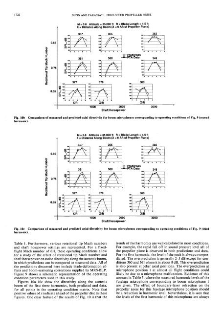
and shaftnoise1 oToMachacousticM=0.8 AltitudeFor example,are given.Tablealmostboom1722 DUNN AND FARASSAT: HIGH-SPEED PROPELLER NOISE= 35,000 ft R= Blade Length =4.5ftX = Distance Along Boom (X < 0 Aft of <strong>Propeller</strong> Plane)Ibo01357 356 383iOoco>01X/RX/R1000 2000Shaft Horsepower3000Fig. lOb Comparison of measured and predicted axial directivity for boom microphones corresponding to operating conditions of Fig. 9 (secondharmonic).M = 0.8 Altitude = 35,000 ft R = Blade Length = 4.5 ftX = Distance Along Boom (X