Hall-effect Speed Sensor HDD
Hall-effect Speed Sensor HDD
Hall-effect Speed Sensor HDD

You also want an ePaper? Increase the reach of your titles
YUMPU automatically turns print PDFs into web optimized ePapers that Google loves.
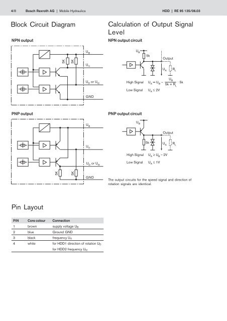
4/8 Bosch Rexroth AG | Mobile Hydraulics <strong>HDD</strong> | RE 95 135/06.03Block Circuit DiagramNPN outputCalculation of Output SignalLevelNPN output circuit5K5KU B5kU BU AR LOutputU f1U Dor U f2GNDHigh Signal U A= U B–Low SignalU A≤ 2VU B5k + R L. 5kPNP outputPNP output circuitU BU BU AR LOutput5kU f1U Dor U f2High SignalLow SignalU A≥ U B– 2VU A≤ 1V5K5KGNDThe output circuits for the speed signal and direction ofrotation signals are identical.Pin LayoutPIN Core colour Connection1 brown supply voltage U B2 blue Ground GND3 black frequency U f14 white for <strong>HDD</strong>1 direction of rotation U Dfor <strong>HDD</strong>2 frequency U f2