
You also want an ePaper? Increase the reach of your titles
YUMPU automatically turns print PDFs into web optimized ePapers that Google loves.
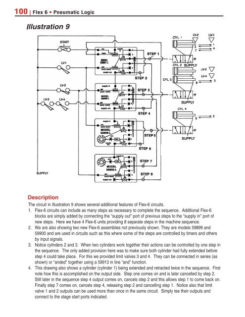
100 | Flex 6 • Pneumatic LogicIllustration 9DescriptionThe circuit in Illustration 9 shows several additional features of Flex-6 circuits.1. Flex-6 circuits can include as many steps as necessary to complete the sequence. Additional Flex-6blocks are simply added by connecting the “supply out” port of previous steps to the “supply in” port ofnew steps. Here we have 4 Flex-6 units providing 8 separate steps in the machine sequence.2. We are also showing two new Flex-6 assemblies not previously shown. They are models 59899 and59900 and are used in circuits such as this where some of the steps are controlled by timers and othersby input signals.3. Notice cylinders 2 and 3. When two cylinders work together their actions can be controlled by one step inthe sequence. The only added provision here was to make sure both cylinder had fully extended beforestep 4 could take place. For this we provided limit valves 3 and 4. They can be connected in series (asshown) or “anded” together using a 59913 in line “and” function.4. This drawing also shows a cylinder (cylinder 1) being extended and retracted twice in the sequence. Firstnote how this is accomplished on the output side. Step one comes on and is later cancelled by step 2.Still later in the sequence step 4 output comes on, cancels step 2 and this allows step 1 to come back on.Finally step 7 comes on, cancels step 4, releasing step 2 and cancelling step 1. Notice also that limitvalve 1 and 2 outputs can be used more than once in the same circuit. Simply tee their outputs andconnect to the stage start ports indicated.