8750-1 - KTH Sales Inc.
8750-1 - KTH Sales Inc.
8750-1 - KTH Sales Inc.

You also want an ePaper? Increase the reach of your titles
YUMPU automatically turns print PDFs into web optimized ePapers that Google loves.
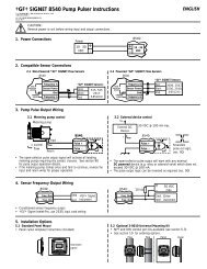
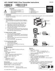
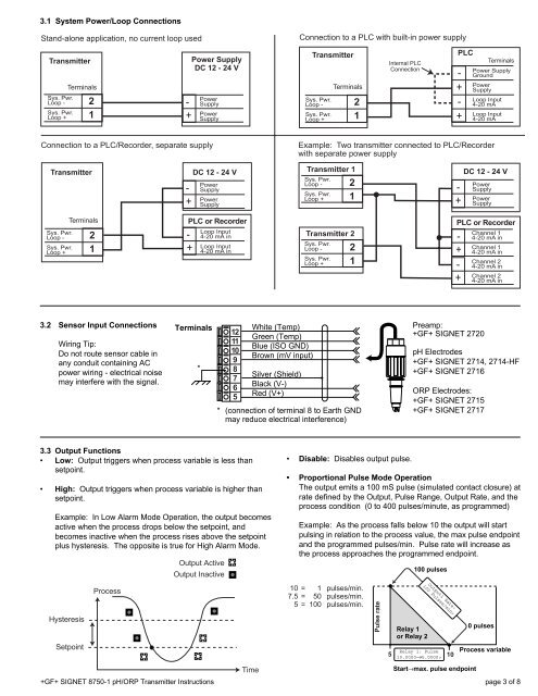
3.1 System Power/Loop ConnectionsStand-alone application, no current loop usedConnection to a PLC with built-in power supplyTransmitterSys. Pwr.Loop -Sys. Pwr.Loop +Terminals21-+Power SupplyDC 12 - 24 VPowerSupplyPowerSupplyTransmitterSys. Pwr.Loop -Sys. Pwr.Loop +Terminals21Internal PLCConnectionPLC-+-+TerminalsPower SupplyGroundPowerSupplyLoop Input4-20 mALoop Input4-20 mAConnection to a PLC/Recorder, separate supplyExample: Two transmitter connected to PLC/Recorderwith separate power supplyTransmitter-+DC 12 - 24 VPowerSupplyPowerSupplyTransmitter 1Sys. Pwr.Loop -Sys. Pwr.Loop +21-+DC 12 - 24 VPowerSupplyPowerSupplySys. Pwr.Loop -Sys. Pwr.Loop +Terminals21PLC or Recorder-+Loop Input4-20 mA inLoop Input4-20 mA inTransmitter 2Sys. Pwr.Loop -Sys. Pwr.Loop +21PLC or Recorder-+-+Channel 14-20 mA inChannel 14-20 mA inChannel 24-20 mA inChannel 24-20 mA in3.2 Sensor Input ConnectionsWiring Tip:Do not route sensor cable inany conduit containing ACpower wiring - electrical noisemay interfere with the signal.Terminals*12111098765White (Temp)Green (Temp)Blue (ISO GND)Brown (mV input)Silver (Shield)Black (V-)Red (V+)* (connection of terminal 8 to Earth GNDmay reduce electrical interference)Preamp:+GF+ SIGNET 2720pH Electrodes+GF+ SIGNET 2714, 2714-HF+GF+ SIGNET 2716ORP Electrodes:+GF+ SIGNET 2715+GF+ SIGNET 27173.3 Output Functions• Low: Output triggers when process variable is less thansetpoint.• High: Output triggers when process variable is higher thansetpoint.Example: In Low Alarm Mode Operation, the output becomesactive when the process drops below the setpoint, andbecomes inactive when the process rises above the setpointplus hysteresis. The opposite is true for High Alarm Mode.HysteresisSetpointProcessOutput ActiveOutput Inactive+GF+ SIGNET <strong>8750</strong>-1 pH/ORP Transmitter InstructionsTime• Disable: Disables output pulse.• Proportional Pulse Mode OperationThe output emits a 100 mS pulse (simulated contact closure) atrate defined by the Output, Pulse Range, Output Rate, and theprocess condition (0 to 400 pulses/minute, as programmed)Example: As the process falls below 10 the output will startpulsing in relation to the process value, the max pulse endpointand the programmed pulses/min. Pulse rate will increase asthe process approaches the programmed endpoint.10 = 1 pulses/min.7.5 = 50 pulses/min.5 = 100 pulses/min.Pulse rate5Relay 1or Relay 2100 pulsesOutput1 Rate:100 Pulses/min>Relay 1: Pulse10.0000→5.0000>10Start→max. pulse endpoint0 pulsesProcess variablepage 3 of 8