MLCC replacements for tantalum capacitors - Yageo
MLCC replacements for tantalum capacitors - Yageo
MLCC replacements for tantalum capacitors - Yageo

You also want an ePaper? Increase the reach of your titles
YUMPU automatically turns print PDFs into web optimized ePapers that Google loves.
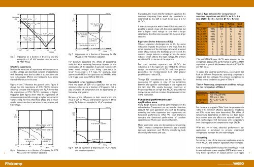
4manufacturers of <strong>tantalum</strong> <strong>capacitors</strong>, electrolytics and<strong>capacitors</strong> in other technologies.Bearing this in mind we start comparing basicper<strong>for</strong>mance characteristics of <strong>MLCC</strong>s and <strong>tantalum</strong><strong>capacitors</strong> by looking at major categories such ascapacitance/volume per case size, rated voltages andtemperature characteristics.Capacitance per unit volumeBased on nominal specifications, <strong>tantalum</strong> <strong>capacitors</strong>offer the highest maximum capacitance at rated voltageof 2 to 4 V. For higher rated voltages, however, i.e.between 6 and 10 V, there is little difference in maximumcapacitance between 0603, 0805 and 1206 Y5V <strong>MLCC</strong>sand <strong>tantalum</strong> <strong>capacitors</strong>.In contrast, X7R <strong>MLCC</strong>s offering the same maximumcapacitance are at least one and sometimes two casesizes larger than their counterparts in Y5V or <strong>tantalum</strong>.Rated voltageFor <strong>tantalum</strong> <strong>capacitors</strong>, the rated voltage is close to thebreakdown voltage and is clearly to be interpreted asmore or less the maximum voltage at which the<strong>capacitors</strong> can operate. In the interests of reliability,there<strong>for</strong>e, designers commonly derate <strong>tantalum</strong><strong>capacitors</strong> to operate at voltages between 20% and 50%below their rated voltage.In contrast to <strong>tantalum</strong>s, the rated voltage of <strong>MLCC</strong>s isfar less than their breakdown voltage and is usuallydetermined by the per<strong>for</strong>mance in dry endurance tests.A point worth noting here is that in order to complywith EIA and EIAJ standards, <strong>MLCC</strong>s are required toundergo long-term reliability testing at twice their ratedvoltage.The obvious conclusion of this is that in circuits whereeither type may be used, to get the same circuit reliabilityit would be necessary to choose a <strong>tantalum</strong> with roughlytwice the rated voltage of the equivalent <strong>MLCC</strong>.Temperature characteristicsIn the temperature range 0 to 85 °C, <strong>tantalum</strong> <strong>capacitors</strong>offer a relatively flat temperature characteristic.<strong>MLCC</strong>s, on the other hand, come in differenttemperature classes defined by their dielectric, such asY5V, Z5U,Y5U, X7R, and X5R.As a general rule one cansay that <strong>for</strong> <strong>MLCC</strong>s, temperature characteristic canalways be improved at the expense of capacitance perunit volume.In general, X5R and X7R specifications are comparable tothose of <strong>tantalum</strong> in the temperature range 0 to 85 °C.This does not mean, however, that in comparing<strong>tantalum</strong> <strong>capacitors</strong> with <strong>MLCC</strong>s, one should consideronly X5R or X7R products. As we’ll show later, Y5V<strong>MLCC</strong>s despite their strong temperature dependencecan offer attractive alternatives to <strong>tantalum</strong> <strong>capacitors</strong>in certain areas.Other general specification itemsThere are many other differences between the generalspecifications of <strong>MLCC</strong>s and <strong>tantalum</strong> <strong>capacitors</strong>. Table2 gives a survey of these differences many of which may,in particular cases, be decisive in deciding on whichtechnology to choose.Table 2 General comparison of <strong>MLCC</strong>sand <strong>tantalum</strong> <strong>capacitors</strong>characteristic Y5V X7R solid<strong>MLCC</strong> <strong>MLCC</strong> Tacapacitance range ++ + ++bipolarity ++ ++ -resistance to pulse voltage ++ ++ +lifetime at T > 85 °C +/- + -high-frequency per<strong>for</strong>mance + ++ -breakdown voltage ++ ++ -voltage dependency (DC) - +/- +product height ++ ++ +SMD compatibility ++ ++ +reliability ++ ++ +In many instances, the criteria in Table 2 may make thechoice between <strong>MLCC</strong> and <strong>tantalum</strong> clear. In otherinstances, however, to make a proper choice we need tolook further at the influence of frequency, temperatureand bias voltage on the more fundamental properties ofimpedance, ESR and ESL.Comparison of impedanceFigure 3 gives a comparison of room-temperatureimpedance as a function of frequency <strong>for</strong> 1 µF<strong>capacitors</strong> in <strong>tantalum</strong> and Y5V <strong>MLCC</strong> technologies.10 2MSD101Aimpedance(Ω)10<strong>tantalum</strong>1<strong>MLCC</strong>10 -110 -2Fig. 3 Impedance as a funcion of frequency <strong>for</strong> a 1 µF<strong>tantalum</strong> capacitor (16 V) and a 1 µF Y5V <strong>MLCC</strong>Since decoupling per<strong>for</strong>mance, in particular, is oftendetermined by the capacitor’s impedance, the lowerimpedance of the <strong>MLCC</strong> <strong>for</strong> frequencies above 100 kHzin this case makes it the preferred choice.Influence of temperature on impedance.The influences of temperature on the decouplingper<strong>for</strong>mance should also be taken in account. For the1 µF <strong>capacitors</strong> in the example above, Fig.4 shows thetemperature dependence of impedance between 0 and+85 °C.Fig. 410 3impedance(Ω)10 21010 -3 10 -2 10 -1 1 10 10 2110 -1<strong>MLCC</strong> 85 ˚C<strong>MLCC</strong> 20 ˚CTa 85 ˚Cf (MHz)MSD102ATa 20 ˚C10 -210 -3 10 -2 10 -1 1 10 10 2f (MHz)Impedance as a function of frequency andtemperature <strong>for</strong> a 1 µF 16 V <strong>tantalum</strong> capacitor anda 1 µF 16 V Y5V <strong>MLCC</strong>From this figure we see that at low frequencies theimpedance of a 1 µF Y5V <strong>MLCC</strong> roughly doubles itsvalue between room temperature and 85 °C. Chieflybecause of this, the frequency at which the impedanceof the Y5V capacitor becomes lower than that of the<strong>tantalum</strong> capacitor of the same values shifts fromapproximately 60 kHz to 200 kHz. Although thissuggests that the frequency range over which the<strong>tantalum</strong> capacitor competes with the <strong>MLCC</strong> isextended at these higher temperatures, most modernapplications in, <strong>for</strong> example, EDP and power suppliesoperate at frequencies well in excess of 100 kHz whichmeans that even with this relatively high dependence ofimpedance on temperature, the Y5V <strong>MLCC</strong> is usuallystill preferred.X7R/X5R <strong>MLCC</strong>sFor X7R and X5R <strong>MLCC</strong>s, the low frequencyimpedance up to 10 kHz is approximately the same as<strong>for</strong> <strong>tantalum</strong> <strong>capacitors</strong>. Above this frequency, however,these <strong>MLCC</strong>s show rapidly decreasing impedancerelative to <strong>tantalum</strong> and this impedance remains lowerover the whole frequency range above 10 kHz.X7R and X5R <strong>capacitors</strong> show hardly any variation inimpedance with temperature so that with increasingtemperature, the difference in impedance between a<strong>tantalum</strong> and X7R/X5R capacitor stays approximatelythe same.Influence of DC-bias on impedanceA well-known feature of <strong>tantalum</strong> <strong>capacitors</strong> is thattheir capacitance remains relatively unchanged whenDC-bias voltage is applied.In contrast, the capacitance of class 2 <strong>MLCC</strong>s falls withDC bias voltage.The magnitude of this fall depends bothon the dielectric material and on the applied fieldstrength. It there<strong>for</strong>e differs <strong>for</strong> X7R and Y5V and <strong>for</strong>each rated voltage.For X7R <strong>MLCC</strong>s, this effect is limited.A typical 16 V typewill lose a maximum of 20% of its capacitance when a16 V bias is applied.For a 16 V Y5V <strong>MLCC</strong>, the effect is relatively large, acapacitor losing over 80% of its impedance when a 16 Vbias voltage is applied.Figure 5 shows the influence of this change on theimpedance of the capacitor. Again we see that, despitethe large dependence on bias voltage, <strong>for</strong> frequenciesabove 100 kHz the impedance levels of the <strong>MLCC</strong> aremuch lower than those of the <strong>tantalum</strong> capacitor. In the1 to 10 MHz region, the difference is a factor 10.5