Register your product now - Radiometer Analytical
Register your product now - Radiometer Analytical
Register your product now - Radiometer Analytical

Create successful ePaper yourself
Turn your PDF publications into a flip-book with our unique Google optimized e-Paper software.
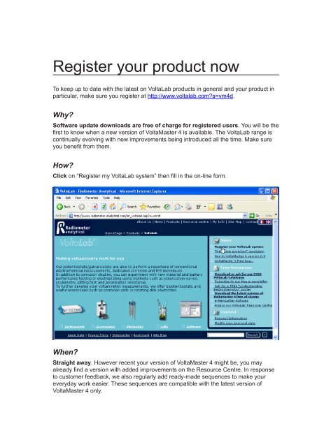
<strong>Register</strong> <strong>your</strong> <strong>product</strong> <strong>now</strong>To keep up to date with the latest on VoltaLab <strong>product</strong>s in general and <strong>your</strong> <strong>product</strong> inparticular, make sure you register at http://www.voltalab.com?s=vm4d.Why?Software update downloads are free of charge for registered users. You will be thefirst to k<strong>now</strong> when a new version of VoltaMaster 4 is available. The VoltaLab range iscontinually evolving with new improvements being introduced all the time. Make sureyou benefit from them.How?Click on “<strong>Register</strong> my VoltaLab system” then fill in the on-line form.When?Straight away. However recent <strong>your</strong> version of VoltaMaster 4 might be, you mayalready find a version with added improvements on the Resource Centre. In responseto customer feedback, we also regularly add ready-made sequences to make <strong>your</strong>everyday work easier. These sequences are compatible with the latest version ofVoltaMaster 4 only.
D21V032 • © HACH LANGE GmbH • Germany • 2013 -06JAll Rights Reserved.
Contents<strong>Register</strong> <strong>your</strong> <strong>product</strong> <strong>now</strong> 1-11. General presentation 51.1 General information.......................................................................................61.2 Make the best use of <strong>your</strong> User’s Manual.....................................................81.3 VoltaLab 21 Economical Electrochemical Laboratory...................................91.4 VoltaLab 06 Educational Electrochemical Laboratory.................................101.5 VoltaLab 10 All-in-one Electrochemical Laboratory.....................................111.6 VoltaLab 40 Dynamic Electrochemical Laboratory......................................121.7 VoltaLab 50 <strong>Analytical</strong> Electrochemical Laboratory....................................131.8 VoltaLab 80 Universal Electrochemical Laboratory ....................................142. Software installation 152.1 System requirements..................................................................................152.2 Before starting installation...........................................................................162.3 Installing VoltaMaster 4...............................................................................172.4 End of installation - Getting started in Routine setup mode........................192.5 Uninstalling VoltaMaster 4...........................................................................233. Getting started 253.1 Physical connections...................................................................................293.2 Before starting VoltaMaster 4......................................................................303.3 User identification........................................................................................313.4 Configure VoltaMaster 4..............................................................................323.5 Set up <strong>your</strong> instrument................................................................................333.6 Set up <strong>your</strong> cell...........................................................................................343.7 Set up the Other settings parameters.........................................................354. VoltaMaster 4 374.1 The VoltaMaster 4 window..........................................................................374.2 Using the VoltaMaster 4 Help file................................................................414.3 Methods available......................................................................................444.4 Creating a sequence...................................................................................664.5 Running a sequence...................................................................................704.6 Processing curves to obtain results............................................................734.7 Printouts......................................................................................................814.8 Error messages...........................................................................................894.9 Troubleshooting list.....................................................................................984.10 The ohmic drop compensation..................................................................1004.11 The VoltaMaster 4 files..............................................................................1034.12 Menus and icons of VoltaMaster 4............................................................105
5. Potentiostats 1135.1 The PGZ and PST series..........................................................................1135.2 The PGP201 Potentiostat - Galvanostat...................................................1356. Combination with additional hardware accessories 1496.1 Rotating Disc Electrode (EDI)...................................................................1496.2 Bipotentiostat............................................................................................1536.3 Rotating Ring and Disc Electrode (EAD)..................................................1566.4 Rotating Disc Stand RDS010....................................................................1616.5 HMDE (MDE150)......................................................................................1636.6 ABU901 Autoburette.................................................................................1726.7 HVB100 High Voltage Booster..................................................................1736.8 HCB005 - HCB010 - HCB020 High Current Boosters..............................1806.9 Additional units - PGZ402 E(X) IN and I(Y) IN sockets.............................1906.10 AMU130 - PGZ402 E(X) IN and I(Y) IN sockets.......................................1916.11 External signal generator - Vg IN socket...................................................1966.12 Measuring an A/D IN signal.......................................................................198
1. General presentationDear Customer,HACH LANGE designs its VoltaLab Electrochemical Laboratory systems with twoconcepts in mind: our software is easy-to-use and our hardware is all-in-one. YourVoltaLab system is computer-controlled so you will find most of the information youneed in the Help file of VoltaMaster 4 Software. Consult the Help index wheneveryou have a question.PotentiostatVoltaLab 40RCB200 *Resistor Capacitor BoxVoltaMaster 4Electrochemical SoftwareCK112Kit of 6 connecting cablesDepending on <strong>your</strong> VoltaLab system, the potentiostat is:VoltaLab system Potentiostat Software Check-upcellVoltaLab 21Economical Electrochemical Laboratory PGP201 VoltaMaster 4 None *VoltaLab 06Educational Electrochemical Laboratory PST006 VoltaMaster 4 None *VoltaLab 10All-in-one Electrochemical Laboratory PGZ100 VoltaMaster 4 RCB200VoltaLab 40Dynamic Electrochemical Laboratory PGZ301 VoltaMaster 4 RCB200VoltaLab 80Universal Electrochemical Laboratory PGZ402 VoltaMaster 4 RCB200VoltaLab 50<strong>Analytical</strong> Electrochemical Laboratory PST050 VoltaMaster 4 RCB200*The RCB200 is not supplied with a VoltaLab 06 and VoltaLab 21.VoltaLab 21/06/10/40/50/80 5Section 1, General presentation
1.1 General informationContact InformationManufacturing SiteEuropean HQHACH LANGE GmbHHACH LANGE GmbHKönigsweg 10 Willstätterstraße 11D-14163 Berlin D-40549 DüsseldorfGERMANYGERMANYTel. +49 (0) 308 09 860 Tel. +49 (0) 211 52 880Fax +49 (0) 308 09 86270 Fax +49 (0) 211 52 88143info@hach-lange.dewww.hach-lange.cominfo@hach-lange.dewww.hach-lange.comSafety Information• Please read this entire manual before unpacking, setting up, or operating thisequipment.• Pay attention to all Danger! and Warning! statements. Failure to do so couldresult in serious injury to the operator or damage to the equipment.• To ensure that the protection provided by this equipment is not impaired, do notuse and do not install this equipment in any manner other than that specified inthis manual.Safety Precautions• The instrument must be connected to an electrical system which complies withapplicable local regulations.• The power cable supplied with the instrument must be connected to an earthedpower supply socket.• In accordance with safety standards, it must be possible to disconnect theexternal power supply of the instrument in its immediate vicinity.• There is a ventilation fan at the rear of the unit. Make sure that the ventilationgrille is not blocked in any way as to constrict the airflow needed to cool theinternal components.• Access to the internal components of the instrument is restricted to Hach Langeor its representatives.6VoltaLab 21/06/10/40/50/80Section 1, Chapter 1: General information
Precautionary LabelsRead all labels and tags attached to the instrument. Personal injury or damage tothe instrument could occur if not observed.This symbol, if noted on the instrument, references the User’s manualfor operation and/or safety information.Electrical and electronic equipment marked with this symbol may notbe disposed of in European public disposal systems after 13 August of2005. In conformity with European local and national regulations (EUDirective 2002/96/EC), European electrical equipment users must <strong>now</strong>return old or end-of life equipment to the Producer for disposal at nocharge to the user.Note: For equipment supplied or produced by HACH LANGE, pleasecontact www.hach-lange.com and select <strong>your</strong> country for instructions onhow to return <strong>your</strong> equipment for proper disposal.This symbol, when noted on the <strong>product</strong>, identifies the location of a fuseor current limiting device.Warning!These VoltaLab systems have been developed to meet the requirements ofelectrochemical applications. It is therefore aimed at experienced users who havethe k<strong>now</strong>ledge required to operate the instrument and implement the securityinstructions enclosed. Please remember that these systems must not, under anycircumstances, be used to perform tests on living beings.We accept no responsibility for using the PGZ100, PGZ301, PGZ402, PST006,PST050 and PGP201 potentiostats and peripheral devices (HVB100, HCB005,HCB010, HCB020, RDS010, CTV101, TACHYPROCESSOR, ED101, EAD10000and AMU130) under conditions that are not specified in this User’s Manual.VoltaLab 21/06/10/40/50/80 7Section 1, Chapter 1: General information
1.2 Make the best use of <strong>your</strong> User's ManualThis User's Manual is common to the following VoltaLab systems:. VoltaLab 21 Economical Electrochemical Laboratory. VoltaLab 06 Educational Electrochemical Laboratory. VoltaLab 10 All-in-one Electrochemical Laboratory. VoltaLab 40 Dynamic Electrochemical Laboratory. VoltaLab 80 Universal Electrochemical Laboratory. VoltaLab 50 <strong>Analytical</strong> Electrochemical LaboratoryIdentify each element of <strong>your</strong> VoltaLab system reading Section 1.Whenever you need information about technical specifications, read also Section 1.Install VoltaMaster 4 reading instructions of Section 2.Setup the system according to the instructions of Section 3.Section 4 describes VoltaMaster 4 and is common to all VoltaLab systems. Thissection sums up the functionalities of VoltaMaster 4 and helps you to use thesoftware. If you want to k<strong>now</strong> more about a particular point, you will be guided tothe help file through keywords.Section 5 provides information on the potentiostat you are using. If relevant(case of a PGP201), it also describes the manual operation of the potentiostat (usewithout a PC and VoltaMaster 4).Section 6 describes the use of additional accessories connected to the potentiostat.You will find the hardware and VoltaMaster 4 settings to run experiments with theseaccessories.8VoltaLab 21/06/10/40/50/80Section 1, Chapter 2: Make the best use of <strong>your</strong> user's manual
1.3 VoltaLab 21 Economical ElectrochemicalLaboratoryThe VoltaLab 21 Economical Electrochemical laboratory is supplied in 2 versions:230 V, 47.5-63 Hz (Part no.: A41A009) and 120 V, 47.5-63 Hz (Part no.: A41A010)Part no. Type DescriptionA41A009 VoltaLab 21, 230V comprising:A08A013 PGP201 - 0 PGP201 Potentiostat/Galvanostat 20V/10Awith Signal GeneratorA96C112 CK112 VoltaLab Cables for cell connectionR31V003 VoltaMaster 4 VoltaMaster 4 Electrochemical SoftwareA95X501 C501X Serial Cable D-9F/2m/D-9F DirectA95S001 C001S Line cord 230V EuroX16V004 Fuse 2.0A Fuse, 2.0 A for PGZ (TT2a)D21V032 - VoltaLab-VoltaMaster 4 User's Manual - EnglishPart no. Type DescriptionA41A010 VoltaLab 21, 120V comprising:A08A013 PGP201 - 0 PGP201 Potentiostat/Galvanostat 20V/10Awith Signal GeneratorA96C112 CK112 VoltaLab Cables for cell connectionR31V003 VoltaMaster 4 VoltaMaster 4 Electrochemical SoftwareA95X501 C501X Serial Cable D-9F/2m/D-9F DirectA95S002 C002S Line cord 230V EuroX16V004 Fuse 2.0A Fuse, 2.0 A for PGZ (TT2a)D21V032 - VoltaLab-VoltaMaster 4 User's Manual - EnglishVoltaLab 21/06/10/40/50/80 9Section 1, Chapter 3: VoltaLab 21 Economical Electrochemical Laboratory
1.5 VoltaLab 10 All-in-one ElectrochemicalLaboratoryThe VoltaLab 10 All-in-one Electrochemical laboratory is supplied in 2 versions:230 V, 47.5-63 Hz (Part no.: R21V011) and 120 V, 47.5-63 Hz (Part no.: R21V012)Part no. Type DescriptionR21V011 VoltaLab 10, 230V comprising:R11V007 PGZ100 - 0 PGZ100 All-in-one PotentiostatA96C112 CK112 VoltaLab Cables for cell connectionR31V003 VoltaMaster 4 VoltaMaster 4 Electrochemical SoftwareA95X501 C501X Serial Cable D-9F/2m/D-9F DirectX16V003 RCB200 Resistor Capacitor Box for VoltaLabA95S001 C001S Line cord 230V EuroX16V004 Fuse 2.0A Fuse, 2.0 A for PGZ (TT2a)D21V032 - VoltaLab-VoltaMaster 4 User's Manual - EnglishD21V030 - RCB200 Operating Instructions - EnglishPart no. Type DescriptionR21V012 VoltaLab 10, 120V comprising:R11V007 PGZ100 - 0 PGZ100 All-in-one PotentiostatA96C112 CK112 VoltaLab Cables for cell connectionR31V003 VoltaMaster 4 VoltaMaster 4 Electrochemical SoftwareA95X501 C501X Serial Cable D-9F/2m/D-9F DirectX16V003 RCB200 Resistor Capacitor Box for VoltaLabA95S002 C002S Line cord 120VX16V004 Fuse 2.0A Fuse, 2.0 A for PGZ (TT2a)D21V032 - VoltaLab-VoltaMaster 4 User's Manual - EnglishD21V030 - RCB200 Operating Instructions - EnglishVoltaLab 21/06/10/40/50/80 11Section 1, Chapter 5: VoltaLab 10 All-in-one Electrochemical Laboratory
1.6 VoltaLab 40 Dynamic ElectrochemicalLaboratoryThe VoltaLab 40 Dynamic EIS and Voltametry Electrochemical laboratory is suppliedin 2 versions:230 V, 47.5-63 Hz (Part no.: R21V007) and 120 V, 47.5-63 Hz (Part no.: R21V008)Part no. Type DescriptionR21V007 VoltaLab 40, 230V comprising:R11V006 PGZ301 - 0 PGZ301 PotentiostatA96C112 CK112 VoltaLab Cables for cell connectionR31V003 VoltaMaster 4 VoltaMaster 4 Electrochemical SoftwareA95X501 C501X Serial Cable D-9F/2m/D-9F DirectX16V003 RCB200 Resistor Capacitor Box for VoltaLabA95S001 C001S Line cord 230V EuroX16V004 Fuse 2.0A Fuse, 2.0 A for PGZ (TT2a)D21V032 - VoltaLab-VoltaMaster 4 User's Manual - EnglishD21V030 - RCB200 Operating Instructions - EnglishPart no. Type DescriptionR21V008 VoltaLab 40, 120V comprising:R11V006 PGZ301 - 0 PGZ301 PotentiostatA96C112 CK112 VoltaLab Cables for cell connectionR31V003 VoltaMaster 4 VoltaMaster 4 Electrochemical SoftwareA95X501 C501X Serial Cable D-9F/2m/D-9F DirectX16V003 RCB200 Resistor Capacitor Box for VoltaLabA95S002 C002S Line cord 120VX16V004 Fuse 2.0A Fuse, 2.0 A for PGZ (TT2a)D21V032 - VoltaLab-VoltaMaster 4 User's Manual - EnglishD21V030 - RCB200 Operating Instructions - English12VoltaLab 21/06/10/40/50/80Section 1, Chapter 6 : VoltaLab 40 Dynamic Electrochemical Laboratory
1.7 VoltaLab 50 <strong>Analytical</strong> ElectrochemicalLaboratoryThe VoltaLab 50 <strong>Analytical</strong> Electrochemical laboratory is supplied in 2 versions:230 V, 47.5-63 Hz (Part no.: R21V015) and 120 V, 47.5-63 Hz (Part no.: R21V016)Part no. Type DescriptionR21V015 VoltaLab 50, 230V comprising:R11V009 PST050 - 0 PST050 <strong>Analytical</strong> PotentiostatA96C112 CK112 VoltaLab Cables for cell connectionR31V003 VoltaMaster 4 VoltaMaster 4 Electrochemical SoftwareA95X501 C501X Serial Cable D-9F/2m/D-9F DirectX16V003 RCB200 Resistor Capacitor Box for VoltaLabA95S001 C001S Line cord 230V EuroX16V004 Fuse 2.0A Fuse, 2.0 A for PGZ (TT2a)D21V032 - VoltaLab-VoltaMaster 4 User's Manual - EnglishD21V030 - RCB200 Operating Instructions - EnglishPart no. Type DescriptionR21V016 VoltaLab 50, 120V comprising:R11V009 PST050 - 0 PST050 <strong>Analytical</strong> PotentiostatA96C112 CK112 VoltaLab Cables for cell connectionR31V003 VoltaMaster 4 VoltaMaster 4 Electrochemical SoftwareA95X501 C501X Serial Cable D-9F/2m/D-9F DirectX16V003 RCB200 Resistor Capacitor Box for VoltaLabA95S002 C002S Line cord 120VX16V004 Fuse 2.0A Fuse, 2.0 A for PGZ (TT2a)D21V032 - VoltaLab-VoltaMaster 4 User's Manual - EnglishD21V030 - RCB200 Operating Instructions - EnglishVoltaLab 21/06/10/40/50/80 13Section 1, Chapter 7 : VoltaLab 50 <strong>Analytical</strong> Electrochemical Laboratory
1.8 VoltaLab 80 Universal ElectrochemicalLaboratoryThe VoltaLab 80 Universal Electrochemical laboratory is supplied in 2 versions:230 V, 47.5-63 Hz (Part no.: R21V009) and 120 V, 47.5-63 Hz (Part no.: R21V010)Part no. Type DescriptionR21V009 VoltaLab 80, 230V comprising:R11V006 PGZ402 - 0 PGZ402 Universal PotentiostatA96C112 CK112 VoltaLab Cables for cell connectionR31V003 VoltaMaster 4 VoltaMaster 4 Electrochemical SoftwareA95X501 C501X Serial Cable D-9F/2m/D-9F DirectX16V003 RCB200 Resistor Capacitor Box for VoltaLabA95S001 C001S Line cord 230V EuroX16V004 Fuse 2.0A Fuse, 2.0 A for PGZ (TT2a)D21V032 - VoltaLab-VoltaMaster 4 User's Manual - EnglishD21V030 - RCB200 Operating Instructions - EnglishPart no. Type DescriptionR21V010 VoltaLab 80, 120V comprising:R11V006 PGZ402 - 0 PGZ402 Universal PotentiostatA96C112 CK112 VoltaLab Cables for cell connectionR31V003 VoltaMaster 4 VoltaMaster 4 Electrochemical SoftwareA95X501 C501X Serial Cable D-9F/2m/D-9F DirectX16V003 RCB200 Resistor Capacitor Box for VoltaLabA95S002 C002S Line cord 120VX16V004 Fuse 2.0A Fuse, 2.0 A for PGZ (TT2a)D21V032 - VoltaLab-VoltaMaster 4 User's Manual - EnglishD21V030 - RCB200 Operating Instructions - English14VoltaLab 21/06/10/40/50/80Section 1, Chapter 8 : VoltaLab 80 Universal Electrochemical Laboratory
2.4 End of installation - Getting started inRoutine setup modeIf you have selected the Routine setup mode, VoltaMaster 4 is launchedautomatically at the end of installation. Then you have to setup the instrument, celland other settings parameters. This parameters are saved so that when you startagain VoltaMaster 4 in Routine setup mode, you do not have to pass again throughthese configuration dialogue boxes.Set up <strong>your</strong> instrument. Connect the potentiostat to the computer serial port COMx (see paragraph 3.1Physical connections).Switch on the potentiostat.. Click the "Test" button. The instrument type (VoltaLab PGP201, PGZ100,PGZ301, PGZ402, PST006 or PST050) and version are displayed.If it is not the case (communication failure (1) message), select "Potentiostat= VoltaLab PGP201 (or PGZ100, PGZ301, PGZ402, PST006 or PST050)",select the communication port (1 to 8) of the PC used for the connection to thepotentiostat for "Serial port" then click again the "Test" button.. Click the "Next" button.For more information, press F1 to consult the Help file, keyword index:Instrument setup.VoltaMaster 4 - Version 7.0x 19Section 2, Software installation
Edit the Other settings parameters. If you are using a VoltaLab 21 (PGP201):Check that "Display curve at end - Raw data" and "Display curve at end -Curve data" are selected.The Other settings are not significant when using a VoltaLab 21.. If you are using a VoltaLab 06, 10, 40, 50 or 80:Check that the "Anti-oscillation filter" is cleared. Select the frequency (50 Hz or60 Hz) of the power supply. This selection is used by VoltaMaster 4 to minimizethe background noise ratio on the measurements. Check that the otherparameters are as shown above.Anti oscillation filterIn potentiostatic mode and for low current measurement ranges (< 100 µA), thepotentiostat may start to oscillate with special electrochemical cells (cells with lowohmic drop and high double layer capacitance). This malfunction can be detectedby using an oscilloscope connected to the PGZ potentiostat "I OUT" or "E OUT"BNC sockets on the front panel. Activate the potentiostat anti oscillation filter inorder to eliminate these oscillations (a check mark is displayed when the filter isactivated).ImportantActivate the anti-oscillation filter only if the system starts to oscillate. In almost anycases, this filter should be disabled.For more information, press F1 to consult the Help file, keyword index:Other settings.20VoltaMaster 4 - Version 7.0xSection 2, Software installation
Edit the Cell setup configuration parametersIf you run a checkup sequence with the RCB200 Resistor Capacitor Box:take care that the "Area" is 1 cm 2 .If you run a sequence on a real cell:. specify the reference electrode you are using (select a predefined type orselect “User defined”);. enter the area of the working and auxiliary electrodes (WORK (WE) – Area andAUX (CE) – Area),. the other Cell setup parameters are to be entered if you intend to calculate acorrosion rate or run a General corrosion (Rp) method. In all other cases, youdo not need to make any changes to the other Cell setup settings.For more information, press F1 to consult the Help file, keyword index:Cell setup.Important:Before clicking the "Finish" button to end the installation, check the Instrument,Other settings, A/D IN configuration and Cell setup parameters. After having clickedthe "Finish" button, these parameters are saved and cannot be changed usingVoltaMaster 4 in Routine setup mode.If you want to change these parameters afterwards, you must switch to anotherVoltaMaster 4 setup mode. You do not have to re-install the software to change thesetup mode.Press F1 to consult the Help file, keyword index:How to select/change the VoltaMaster 4 setup modes?22VoltaMaster 4 - Version 7.0xSection 2, Software installation
2.5 Uninstalling VoltaMaster 4VoltaMaster 4 must be uninstalled using the “Start - Settings - Control Panel - Add/Remove Programs" of Windows then select "VoltaMaster 4" and the "Add/Remove"button. All the files that have been created and copied by the VoltaMaster 4 setupprogram are removed from the VoltaMaster installation directory. The files that havebeen created by the setup program are suppressed from the C:\Windows\Systemdirectory. The VoltaMaster 4 icons placed in the “Start – All Programs – VoltaLab”are removed. The files created after the VoltaMaster 4 installation are not affectedby the uninstall program (for example, the result files, the operating condition filesand experiment text files).VoltaMaster 4 - Version 7.0x 23Section 2, Software installation
24VoltaMaster 4 - Version 7.0xSection 2, Software installation
3. Getting startedFor a VoltaLab 10, VoltaLab 40, VoltaLab 50 or VoltaLab 80RS232 cable9-pin female / 9-pin femaletype: C501XPart no. A95X501PC serial port COM1(or COM2to COM8)Caution: Connect the PC tothis socket (the 2 "RS232C"sockets are not equivalent)LINE FUSE T2A L250V120/230 Vac 47.5-63 Hz 170 VARS232C115230MADE IN FRANCE RADIOMETER ANALYTICAL S.A.To a mains socketLine cord 230 V (Part no. A95S001)Line cord 120 V (Part no. A95S002)Banana/banana cable4Resistor Capacitor BoxRCB200RCB2001.21 K⏐100 K ⏐A B C DAUX REF WORK1 2 34.99 K⏐ 10 K⏐4.7 nF 1 µFVoltaLab 10ONI OUT E OUT Vg INA/D IND/A OUTREFAUXSENSEWORKCELLBlackbanana plugsBanana plug2 314BNC plugPL259 plugsBanana plugCK112 Kit of 6 connecting cablesCable supplied with RCB200VoltaLab 21/06/10/40/50/80 25Section 3, Chapter 1: Physical connections
For a VoltaLab 21RS232 cable9-pin female / 9-pin femaletype: C501XPart no. A95X501PC serial port COM1(or COM2to COM8)Line cord 230 V (Part no. A95S001)Line cord 120 V (Part no. A95S002)LI-BATTERY3.6 VSIZE AA/R6LINE FUSE T800mA L250V120/230 Vac 47.5-63 Hz 70 VARS232C115230MADE IN FRANCERADIOMETER ANALYTICAL S.A.Electrical zeroGround/casing jumperCasing4RCB2001.21 K⏐To a mains socket4.99 K⏐ 10 K⏐Functional ground100 K ⏐4.7 nF 1 µFA B C DAUX REF WORKBanana/banana cable1 23ONPGP201POTENTIOSTAT GALVANOSTATOperation/StandbyVg OUTVs OUTVg INAUXOFFStart/StopE OUTI OUTREFWORKBlackbanana plugsBanana plug2 314BNC plugPL259 plugsBanana plugCK112 Kit of 6 connecting cablesCable supplied with RCB200Ground/casing jumperThe electrical zero and the casing are normally connected together by a jumper(the non-floating mode is used). The casing socket is itself connected to thefunctional ground socket which is connected to the earth via the 3-lead line cord.In some applications, you can also use the PGP201 in floating mode: in this case,remove the ground/casing jumper and connect to the earth the WORK or REFelectrode (the cell container can also be earthed). The table below sums up thedifferent connections that are possible at the 3 banana sockets on the rear panel ofthe PGP201.26VoltaLab 21/06/10/40/50/80Section 3, Chapter 1: Physical connections
For a VoltaLab 06RS232 cable9-pin female / 9-pin femaletype: C501XPart no. A95X501PC serial port COM1(or COM2to COM8)Caution: Connect the PC tothis socket (the 2 "RS232C"sockets are not equivalent)LINE FUSE T2A L250V120/230 Vac 47.5-63 Hz 170 VARS232C115230MADE IN FRANCE RADIOMETER ANALYTICAL S.A.To a mains socketLine cord 230 V (Part no. A95S001)Line cord 120 V (Part no. A95S002)Banana/banana cablePST006 Educational Potentiostat4Resistor Capacitor BoxRCB200RCB2001.21 K⏐100 K ⏐4.99 K⏐ 10 K⏐A B C DAUX REF WORK1 2 34.7 nF 1 µFONREFAUXWORKCELLBlackbanana plugsBanana plug2 314BNC plugPL259 plugsBanana plugCable supplied with RCB20028VoltaLab 21/06/10/40/50/80Section 3, Chapter 1: Physical connections
3.2 Before starting VoltaMaster 4. Switch on the computer then start Windows.. Select "Start > Control Panel > Display > Settings" and select a screenresolution in the "Desktop area" equal to 600 x 800 or greater. Also click the"Advanced" button then select "DPI settings" = "Normal size (96 ppp)" (*).(*) recommended30VoltaLab 21/06/10/40/50/80Section 3, Chapter 2: Before starting VoltaMaster 4
3.3 User identificationIf you selected the Supervisor/Operator setup mode during software installation,any time you launch VoltaMaster 4, you are prompted to select a user and enterhis password. It can be any user already registered.By default VoltaMaster 4 offers you a selection of two users. One is named“Supervisor”, has a level of “supervisor” and his password is “password” (smallcase letters). The second one is named “Operator”, has a level of “operator” andhis password is also “password”. Any new user created will have "password" as hisinitial password.· Connected in “Supervisor” level, you can run any sequence and modifythem. You can manipulate any curve and you can modify them.· Connected in “Operator” level, you can run any sequence but cannot modifythem. However you can run them under a different name. You can manipulateany curve and you can modify them.2. Enter "password"(small case letters)1. Select a User level3. Click the "OK" buttonFor more information about how to change <strong>your</strong> name and password and how tocreate a user, press F1 from this box or consult the Help file, keyword index:User identification.VoltaLab 21/06/10/40/50/80 31Section 3, Chapter 3: User identification
3.4 Configure VoltaMaster 4. Start VoltaMaster 4 (select "Start - Program files – VoltaLab - VoltaMaster 4").. Log on as a "Supervisor" or an "Operator".. Consult the tip of the day and close the box.. If you hear a regular "Bip bip bip...", it means that the PC is not connected to apotentiostat: select the "Toolbar" menu then clear the "Monitor Bar" option.. Click the icon in the toolbar or select the "File" menu then the "Newsequence" command. The Laboratory logbook window of a new experiment isopened.If you selected the Routine setup mode while installing VoltaMaster 4, just startthe software (select "Start - Program files – VoltaLab - VoltaMaster 4") then clickthe icon in the toolbar or select the "File" menu then the "New sequence"command.The Laboratory logbook window of a new experiment is opened.32VoltaLab 21/06/10/40/50/80Section 3, Chapter 4: Configure VoltaMaster 4
3.5 Set up <strong>your</strong> instrumentIf you selected the Routine setup mode while installing VoltaMaster 4, theInstrument settings are entered at the end of the software installation and cannotbe changedIf you want to change these parameters afterwards, you must switch to anotherVoltaMaster 4 setup mode. You do not have to re-install the software to change thesetup mode.Press F1 to consult the Help file, keyword index:How to select/change the VoltaMaster 4 setup modes?If you selected the Full or Supervisor/Operator setup modes while installingVoltaMaster 4:. Select the "Settings" menu then the "Instrument setup" command. If you donot have access to the "Instrument setup" command, it means that the monitorbar is activated. Disable the toolbar as follows: select the "Toolbar" menu thendeselect the "Monitor Bar" option.The Instrument setup for a VoltaLab 10 (PGZ100). Click the "Test" button. The instrument type (VoltaLab PGP201, PGZ100,PGZ301, PGZ402, PST006 or PST050) and version are displayed.. If it is not the case (communication failure (1) message), select "Potentiostat= VoltaLab PGP201 (or PGZ100, PGZ301, PGZ402, PST006 or PST050)",select the communication port (1 to 8) of the PC used for the connection to thepotentiostat for "Serial port" then click again the "Test" button.For more information, consult the Help file, keyword index:Instrument setup.VoltaLab 21/06/10/40/50/80 33Section 3, Chapter 5: Set up <strong>your</strong> instrument
3.6 Set up <strong>your</strong> cellIf you selected the Routine setup mode while installing VoltaMaster 4, the Cellsettings are entered at the end of the software installation and cannot be changedIf you want to change these parameters afterwards, you must switch to anotherVoltaMaster 4 setup mode. You do not have to re-install the software to change thesetup mode.Press F1 to consult the Help file, keyword index:How to select/change the VoltaMaster 4 setup modes?If you selected the Full or Supervisor/Operator setup modes while installingVoltaMaster 4:. If you run a checkup sequence with the RCB200 Resistor Capacitor Box, takecare that the "Area" is 1 cm 2 .. If you run a sequence on a real cell, perform the following operations:Select the "Settings" menu then the "Cell setup" command.Specify the reference electrode you are using (select a predefined type orselect “User defined”). Enter the area of the working and auxiliary electrodes(WORK (WE) – Area and AUX (CE) – Area). The other Cell setup parametersare to be entered if you intend to calculate a corrosion rate or run a Generalcorrosion (Rp) method. In all other cases, you do not need to make anychanges to the other Cell setup settings.For more information, consult the Help file, keyword index:Cell setup.34VoltaLab 21/06/10/40/50/80Section 3, Chapter 6: Set up <strong>your</strong> cell
3.7 Set up the Other settings parametersIf you selected the Routine setup mode while installing VoltaMaster 4, the Othersettings are entered at the end of the software installation and cannot be changedIf you want to change these parameters afterwards, you must switch to anotherVoltaMaster 4 setup mode. You do not have to re-install the software to change thesetup mode.Press F1 to consult the Help file, keyword index:How to select/change the VoltaMaster 4 setup modes?.If you selected the Full or Supervisor/Operator setup modes while installingVoltaMaster 4, select the "Settings" menu then the "Other settings" command.. If you are using a VoltaLab 21 (PGP201):Check that "Display curve at end - Raw data" and "Display curve at end -Curve data" are selected.The Other settings are not significant when using a VoltaLab 21.. If you are using a VoltaLab 06, 10, 40, 50 or 80:Check that the "Anti-oscillation filter" is cleared. Select the frequency (50 Hz or60 Hz) of the power supply. This selection is used by VoltaMaster 4 to minimizethe background noise ratio on the measurements. Check that the otherparameters are as follows:VoltaLab 21/06/10/40/50/80 35Section 3, Chapter 7: Set up Other settings parameters
Anti oscillation filterIn potentiostatic mode and for low current measurement ranges (< 100 µA), thepotentiostat may start to oscillate with special electrochemical cells (cells with lowohmic drop and high double layer capacitance). This malfunction can be detectedby using an oscilloscope connected to the PGZ potentiostat "I OUT" or "E OUT"BNC sockets on the front panel. Activate the potentiostat anti oscillation filter inorder to eliminate these oscillations (a check mark is displayed when the filter isactivated).ImportantActivate the anti-oscillation filter only if the system starts to oscillate. In almost anycases, this filter should be disabled.For more information, consult the Help file, keyword index:Other settings.. Quit VoltaMaster 4 and start it again to save the configuration of "Instrumentsetup", "Cell setup" and "Other settings" as default parameters.Your VoltaLab system is ready. To become familiar with <strong>your</strong> VoltaLab system,Consult the Help file, keyword index:Demonstration.Energy saver: If <strong>your</strong> computer is fitted with an energy saver, you must disableit before starting an experiment with VoltaMaster 4. If this is not done, thecommunication between the computer and the potentiostat might be stopped aftera long period without key action. If this is the case, the experiment is stopped.36VoltaLab 21/06/10/40/50/80Section 3, Chapter 7: Set up Other settings parameters
4. VoltaMaster 44.1 The VoltaMaster 4 windowIn Full and Supervisor/Operator modes3. General bar2. Menu bar1. Title bar4. Curve type bar5. Monitor bar6. Initial data(see section 4-4)7. Application window- Laboratory logbook(see section 4-4)8. Status barIn Routine mode9. Application window:Curve, Results folder, Points (see section 4-6)3. General bar2. Menu bar1. Title bar4. Curve type bar6. Initial data(see section 4-4)7. Application window- Laboratory logbook(see section 4-4)8. Status bar9. Application window:Curve, Results folder, Points (see section 4-6)VoltaMaster 4 - Version 7.0x 37Section 4, Chapter 1: The VoltaMaster 4 window
1. Title barThe Title bar displays the name of software (“VoltaMaster 4” or “VoltaMaster 4Routine” depending on you are running the software in Full, Supervisor/Operator orRoutine mode) and the name of the active application window (e.g. demonstrationcurve “Mott Schottky 000 01S.CRV”).2. Menu barThe Menu bar lists the menus available in VoltaMaster 4. Selecting one of thesemenus gives access to a series of commands (e.g. from a curve active window, the“Edit” menu gives access to the following commands: “Copy”, “Title”, “Legend” and“Set font”).The available menus depend on the type of the active application window(“Laboratory logbook” or “curve” application window) and the setup mode ofVoltaMaster 4 (Full, Supervisor/Operator or Routine).3. General barThe General bar comprises icons. An icon is activated by clicking the mouse button.VoltaMaster 4 icons represent shortcuts for the more common functions of thesoftware. To hide or display the General bar, choose “General bar” from the “Toolbar”menu. The General bar can be moved around the VoltaMaster 4 window: Click on itthen drag the mouse to the place it. Double clicking the General bar will replace thebar in its original position.Note that in Routine setup mode, icons are 4 times larger and limited to load, printand run/stop command icons.4. Curve type barThe Curve type bar includes curve display parameters relating to the curve activewindow. To hide or display the Curve type bar, choose “Curve type bar” from the“Toolbar” menu. The Curve type bar provides quick mouse access to curve displayparameters. After having selected a curve type option, VoltaMaster 4 displays thecurve(s) of the current graph with the new axes.Curve type bar - TypeSelect here the type of curve you want to display between “Normal”, “Nyquist Z”,“Nyquist Y”, “Bode”, “Evans”, “Schottky”, “1/C² = f (E)”.Consult the Help file, keyword index:Type (Curve type bar).38VoltaMaster 4 - Version 7.0xSection 4, Chapter 1: The VoltaMaster 4 window
Curve type bar - XX is the abscissa axis of a graph window. When you open a curve, the curve axissystem used is defined as Y1 = f(X). You can select different types of X axesdepending on the curve displayed: potential, current, time, frequency, module, phase,capacitance, resistance, A/D IN (V), reprocessed A/D IN, corrosion, concentration orquantity of electricity.Consult the Help file, keyword index:X (Curve type bar).Curve type bar - Y1Y1 is the ordinate axis displayed on the left hand side of the graph window. Whenyou open a curve, the curve axis system used is defined as Y1 = f(X). As for the Xabscissa axis, you can select different types of Y1 axes for depending on the curvedisplayed.Consult the Help file, keyword index:Y1 (Curve type bar).Curve type bar - Y2Y2 is the ordinate axis displayed on the right hand side of the graph window. Clickin this “Y2” box if you want to superimpose to the Y1 = f(X) curve(s), the same curveusing a new axis system Y2 = f(X). To display the curve(s) of a current graph in oneaxis system only (Y1 = f(X)), select “Y2 = No”. As for the X abscissa axis, you canselect different types of Y2 axes for depending on the curve displayed.Consult the Help file, keyword index:Y2 (Curve type bar).5. Monitor barThe Monitor bar gives information about the status of the cell and the potentiostat.When the potentiostat is not connected or not switched on, short beeps are emitted(deselect the “Toolbar - Monitor bar” command). On starting VoltaMaster 4 for thefirst time, the Monitor bar is active (displayed). Select the “Toolbar - Monitor bar”command to display or hide the Monitor bar. When an experiment is running, theMonitor bar is replaced by a Run bar.The Monitor bar is not available if you are running VoltaMaster 4 in Routine setupmode.Consult the Help file, keyword indexes:Monitor bar and Run bar.VoltaMaster 4 - Version 7.0x 39Section 4, Chapter 1: The VoltaMaster 4 window
6. Application window - Initial dataThe initial data of an experiment can be edited in this window. If you are runningVoltaMaster 4 in Routine setup mode, the initial data are displayed for consultationonly (cannot be edited).The name of the experiment file is displayed at the top of window (e.g. Mott Schottky.EXP). This name comprises the name of the experiment (Mott Schottky) and the EXPextension showing that it is an experiment file.Consult the Help file, keyword index:Initial data.7. Application window - Laboratory logbookThe application note of an experiment can be edited in this window.If you are running VoltaMaster 4 in Routine setup mode, the application note isdisplayed for consultation only (cannot be edited).Consult the Help file, keyword index:Laboratory logbook.8. Status barThe Status bar is displayed at the bottom of the VoltaMaster 4 window. To displayor hide the status bar, use the “Status Bar” command in the “Toolbar” menu. If youare running VoltaMaster 4 in Routine setup mode, you cannot hide the Status baras the “Toolbar” menu is not available. The left area of the status bar describesactions of menu items as you use the arrow keys to navigate through menus. Thisarea similarly shows messages that describe the actions of toolbar buttons as youdepress them, before releasing them. If after viewing the description of the toolbarbutton command you wish not to execute the command, then release the mousebutton while the pointer is off the toolbar button. The left area also displays thecoordinates of a point shown by the cursor when the mouse pointer is moved arounda curve area. In Full or Supervisor/Operator setup modes, the status bar also showsthe name of the user connected.Consult the Help file, keyword index Status bar.9. Application window - CurveThis window is displayed after having run an experiment or loaded a curve. Thename of the curve file is displayed at the top of window (e.g. Mott Schottky 00001S.CRV). This name comprises the name of the experiment (Mott Schottky), the“000_01S” characters describing the method attached to the curve and the CRVextension showing that it is a curve file. A Points and a Results thumbnails areavailable to display the experimental data and results of calculations attached to thecurve.Consult the Help file, keyword indexes:Result folder or points folder.40VoltaMaster 4 - Version 7.0xSection 4, Chapter 1: The VoltaMaster 4 window
4.2 Using the VoltaMaster 4 Help file1 3245678910VoltaMaster 4 - Version 7.0x 41Section 4, Chapter 2: Using the VoltaMaster 4 Help file
Adding text to a topicAdditional information can be added to a VoltaMaster 4 help topic. Perform thefollowing operations:- Display the topic (use the “Search” function for example).- Select the “Annotate...” command of the “Edit” menu.- In the “Annotate” dialogue box, type the text you want to add. It is possible tocopy the whole contents (or a part of the contents) of the “Current annotation”box into the “Clipboard Viewer” of Windows: highlight the text to be copiedand select the “Copy” button. It is also possible to import the contents of the“Clipboard Viewer” of Windows by selecting the “Paste” button (the contents ofthe “Clipboard Viewer” is displayed at the cursor insertion point).Important: the “Paste” command is not valid if the contents of the “ClipboardViewer” has been obtained other than by the “Edit - Copy” command ofVoltaMaster 4.- After having typed the text, select the “Save” button. The “Annotate” dialoguebox is closed and a green paper clip is displayed at the top of the topic. Todisplay the contents of the annotation, click this paper clip or select it with the“TAB” key followed by “ENTER”.To remove an annotation of a topic, select the “Annotate...” command in the “Edit”menu. In the “Current annotation” dialogue box, select the “Delete” button: thepaper clip is deleted from the topic screen. Use the “Annotate...” command in the“Edit” menu to get custom made help topics on VoltaMaster 4 (including practicalexamples for instance).Adding bookmarks to a topicA bookmark placed in a topic allows you to find the most common topics quickly.Perform the following operations to place a bookmark in a topic:- select the topic then the “Define” command in the “Bookmark” menu,- the title of the selected topic is displayed for the “Bookmark name” box.Another bookmark name can be typed. Select the “OK” button .To display a topic having a bookmark, perform the following operations:- select the “Bookmark” menu. A list of the available bookmarks are displayed,- select the bookmark name. The topic having the bookmark selected isdisplayed.To remove a bookmark from a topic, select the “Define” command in the“Bookmark” menu. Select the bookmark name in the list displayed and select the“Delete” button.VoltaMaster 4 - Version 7.0x 43Section 4, Chapter 2: Using the VoltaMaster 4 Help file
4.3.1 Open Circuit PotentialThe Open Circuit Potential corresponds to the WORK potential measured versus theREF potential. This method displays the OCP of the sample versus time.Consult the Help file, keyword indexes:Open Circuit Potential - Method editing and Open Circuit Potential -Measurements and curve files.4.3.2 Pot. Tutorial CVThis simplified Pot. Cyclic voltammetry sweeps the potential at a given rate up to300 mV/s (12.5 mV/s for a VoltaLab 21) and measures the current. The experimentalcurve obtained is k<strong>now</strong>n as a polarisation curve or a “voltammogram”. The stepamplitude and step duration are determined in order to get the best measurementresolution. These values depend on the mains frequency (50 Hz or 60 Hz) specified inthe “Instrument – Other settings”. Auto ranging for current measurement is availableirrespective of the selected scan rate.Consult the Help file, keyword indexes:Pot. Tutorial CV - Method editing and Pot. Tutorial CV - Measurements andcurve files.4.3.3 Pot. Tutorial CAImposes a potential and measures the current. WORK potential versus REF ismaintained at a Set potential. This selectable Set potential can be equal to the “Free”or to the “Last” potential. The real-time plot displays current versus time like a ChronoAmperometry but potentials are not recorded. Method available with VoltaLab 10,VoltaLab 21, VoltaLab 40 VoltaLab 50 and VoltaLab 80.Consult the Help file, keyword indexes:Pot. Tutorial CA - Method editing and Pot. Tutorial CA - Measurements andcurve files.VoltaMaster 4 - Version 7.0x 45Section 4, Chapter 3: Methods available
4.3.4 Pot. Tutorial EIS (Impedance)This simplified Electrochemical Impedance Spectroscopy (EIS) will generate anelectrochemical impedance spectrum at a given DC potential. This spectrumreports the impedances measured at various frequencies with a superimposed ACsignal on a given DC potential. Nyquist or Bode diagrams are available as a realtimeplot display. Method available with VoltaLab 10, VoltaLab 40 and VoltaLab 80.Consult the Help file, keyword indexes:Pot. Tutorial EIS (Impedance) - Method editing and Pot. Tutorial EIS(Impedance) - Measurements and curve files.Visual EIS:A virtual front panel is also available by selecting the “Settings - Visual EIS”command. This tool can be used to set a DC potential, and an AC amplitude, afrequency and to monitor the impedance data. No record of the data is provided. Itis useful to determine the best settings for a potentiostatic EIS experiment.Consult the Help file, keyword index:Visual EIS.4.3.5 Pot. Interactive CVThe Pot. Interactive CV is the perfect tool to record a polarisation curve andparticularly to investigate any new electrochemical samples. You can set thepotential setpoints versus the OCP (select OCP (Free)) or the reference electrode(select REF potential). You can modify the potential setpoints during the experimentitself. The interactive key allows you to hold the potential, reverse the scan directionand modify the Potential 1 and Potential 2 limits at any time. The potential, thecurrent and the total coulomb charge are displayed on the virtual front panel in realtime during the experiment.Consult the Help file, keyword indexes:Pot. Interactive CV - Method editing and Pot. Interactive CV - Measurementsand curve files.4.3.6 Pot. Cyclic VoltammetryCyclic (and linear) voltammetries sweep the potential at a given rate and measurethe current. The experimental curve obtained is k<strong>now</strong>n as a polarisation curve ora “voltammogram”. The scan rate can be programmed up to 20 V/s (10 mV/s for aVoltaLab 21). Auto ranging for current measurement is available depending on thescan rate.Consult the Help file, keyword indexes:Pot Cyclic Voltammetry - Method editing and Pot Cyclic Voltammetry -Measurements and curve files.46VoltaMaster 4 - Version 7.0xSection 4, Chapter 3: Methods available
Visual IFVA virtual front panel is also available by selecting the “Settings - Visual IFV”command. This tool can be used to set a potential and measure the current just asif <strong>your</strong> instrument was an analog instrument. No record of the data is provided.Consult the Help file, keyword index:Visual IFV.4.3.7 Pot. CV 4 limitsThe Pot. CV 4 limits method is the only VoltaMaster 4 method that allows to runcyclic voltammetries starting and ending at a same potential value such as theOpen circuit potential (OCP) for example. The scan rate can be programmed upto 500 mV/s. Auto ranging for current measurement is available depending on thescan rate. Method available with VoltaLab 10, VoltaLab 06, VoltaLab 40, VoltaLab50 and VoltaLab 80.Consult the Help file, keyword indexes:Pot CV 4 limits - Method editing, Pot CV 4 limits - Measurements and curvefiles.4.3.8 Pot. Linear VThe Pot. Linear V is a linear voltammetry between two applied potential set points.The potential is swept at a given rate and the current is measured. The scan ratecan be programmed up to 15 000 mV/s (10 mV/s with a VoltaLab 21). The stepamplitude and step duration are determined from the potential limits and the scanrate entered. Autoranging for current measurement is available irrespective ofthe selected scan rate. Points are saved at a selectable rate (as many as 1 in 32points).Consult the Help file, keyword indexes:Pot. Linear V - Method editing and Pot. Linear V - Measurements and curvefiles.4.3.9 Chrono AmperometryA potential step induces a current change. The current is recorded while the WORKpotential is maintained at a pre-set value versus the REF potential.Consult the Help file, keyword indexes:Chrono Amperometry - Method editing and Chrono Amperometry -Measurements and curve files.VoltaMaster 4 - Version 7.0x 47Section 4, Chapter 3: Methods available
4.3.10 Chrono CoulometryA potential step induces a current change. The charge is the integration of thecurrent versus time. The charge (Q) is recorded while the WORK potential ismaintained at a pre-set value versus the REF potential. A digital integrationprovides Q. The current is also recorded.Consult the Help file, keyword indexes:Chrono Coulometry - Method editing and Chrono Coulometry - Measurementsand curve files.4.3.11 Chrono PotentiometryA current step induces a potential change. The WORK potential is measured versusthe REF potential while the current is maintained at a pre-set value. The current isalso recorded.Consult the Help file, keyword indexes:Chrono Potentiometry - Method editing and Chrono Potentiometry -Measurements and curve files.4.3.12 Gal. CoulometryA current step induces a potential change. The charge is the integration of thecurrent versus time. The total charge consumed (Q) and the WORK potentialand AUX potential measured versus the REF are recorded while the current ismaintained at a pre-set value. The method stops when a total charge, a measuredpotential, a drift threshold in potential or a maximum duration has been reached.Method available with VoltaLab 06, VoltaLab 10, VoltaLab 40 VoltaLab 50 andVoltaLab 80.Consult the Help file, keyword indexes:Gal. Coulometry - Method editing and Gal. Coulometry - Measurements andcurve files.48VoltaMaster 4 - Version 7.0xSection 4, Chapter 3: Methods available
4.3.13 Pot. Dynamic EIS (Impedance)Electrochemical Impedance Spectroscopy (EIS) is used to investigate the kineticsof electrochemical processes. A dynamic EIS experiment will generate a set ofindividual electrochemical impedance spectra obtained at different DC potentials.Each individual spectrum reports the impedances measured at various frequencieswith a superimposed AC signal on a given DC potential. Dynamic EIS programmingcan generate:- Frequency scan at a single DC potential- Frequency scans at specified time intervals (at a single DC potential)- Frequency scans at different DC potentials (from initial to final in pre-set potentialsteps)- Frequency scans at specified time intervals at OCP in between each EIS (sequencemade of a succession of OCP with polarisation at end and Pot. Tutorial EIS with DCpotential = Free and OCP at end)Nyquist or Bode diagrams are available as a real-time plot display. Method availablewith VoltaLab 40 and VoltaLab 80.Consult the Help file, keyword indexes:Pot. Dynamic EIS (Impedance) - Method editing and Pot. Dynamic EIS(Impedance) - Measurements and curve files.4.3.14 Pot. Expert EIS (Impedance)The Pot. Expert EIS (Impedance) method enables you to get more accurate resultsthan with the Pot. Tutorial or Dynamic EIS methods. This expert-dedicated methodallows to edit up to 3 segments along the frequency range with the followingappropriate parameters: Frequency scan limits, AC amplitude, Frequency resolution(Freq. per decade), Number of measurement repetitions or number of sine wavesupon which frequency is considered (Repeat meas.), Number of measurementstaken for the mean calculation (Average last), Delay before integration and ACcurrent measuring range.If you compare with the Pot. Dynamic EIS (Impedance) method, where all theparameters have been set to give you a spectrum as rapidly as possible, a Pot.Expert EIS method will deliver a better result because you will allow more time forstabilisation and integration when you need it.Only one file is generated. Method available with VoltaLab 40 and VoltaLab 80.Consult the Help file, keyword indexes:Pot. ExpertEIS (Impedance) - Method editing and Pot. Expert EIS (Impedance) -Measurements and curve files.VoltaMaster 4 - Version 7.0x 49Section 4, Chapter 3: Methods available
4.3.15 Pot. Fixed Freq. EIS (Capacitance)The WORK DC potential versus REF is imposed and the ElectrochemicalImpedance is recorded at one fixed frequency with an AC signal superimposedon the DC potential. The potential is scanned from Potential 1 towards Potential2 in potential/time steps. A real-time plot displays -Zimaginary and Z real versuspotential. Method available with VoltaLab 40 and VoltaLab 80.Consult the Help file, keyword indexes:Pot. Fixed Freq. EIS (Capacitance) - Method editing and Pot. Fixed Freq. EIS(Capacitance) - Measurements and curve files.4.3.16 Gal. Tutorial EIS (Impedance)Electrochemical Impedance Spectroscopy (EIS) is used to investigate the kineticsof electrochemical processes. A Gal. Tutorial EIS experiment will generate anelectrochemical impedance spectrum obtained at a given DC current. Thisspectrum reports the impedances measured at various frequencies with asuperimposed AC signal on a given DC current. Gal. Tutorial EIS programminggenerates a Frequency scan at a single DC current. The WORK DC current can beset at ±1 A. The Electrochemical Impedance Spectrum can be recorded from40 kHz down to 1 mHz with a resolution of up to 20 points per decade offrequencies. The AC current amplitude can be set from 5 nA up to 1 A providedthat DC + AC current is within the range –1 A/+1 A. Nyquist or Bode diagramsare available as a real-time plot display. Method available with VoltaLab 40 andVoltaLab 80.Consult the Help file, keyword indexes:Gal. Tutorial EIS (Impedance) - Method editing and Gal. Tutorial EIS(Impedance) - Measurements and curve files.50VoltaMaster 4 - Version 7.0xSection 4, Chapter 3: Methods available
4.3.17 Gal. Expert EIS (Impedance)This expert-dedicated method allows to edit up to 3 segments along the frequencyrange with the following appropriate parameters: Frequency scan limits, ACamplitude, Frequency resolution (Freq. per decade), Number of measurementrepetitions or number of sine waves upon which frequency is considered (Repeatmeas.), Number of measurements taken for the mean calculation (Average last)and Delay before integration.The Gal. Expert EIS method will deliver accurate results as you can allow moretime for stabilisation and integration when you need it.The WORK DC current can be set at ±1.25 A, ±2.5 A, ±5 A, ±10 A, ± 20 Adepending on the High Current Booster used. The Electrochemical ImpedanceSpectrum can be recorded from 40 kHz down to 1 mHz with a resolution of up to 20points per decade of frequencies. The AC current amplitude can be set from 0.5 %up to 10 % of the current range provided that DC + AC current is within the range±1.25 A, ±2.5 A, ±5 A, ±10 A, ± 20 A depending on the High Current Booster used.Nyquist or Bode diagrams are available as a real-time plot display.Only one file is generated. Method available with VoltaLab 80 associated with aHigh Current Booster.Consult the Help file, keyword indexes:Gal. Expert EIS (Impedance) - Method editing and Gal. Expert EIS (Impedance)- Measurements and curve files.4.3.18 Pitting corrosionThe potential is scanned in anodic or cathodic direction from the rest potential orfrom a slightly cathodic potential at a given slow scan rate. The current is measuredversus the imposed potential. When the current reaches a user-selectable limitvalue, the experiment can be stopped or the potential can be held for a given timethen reversed. The experiment stops when a potential or a current value has beenreached. The voltammetric curve is stored.Consult the Help file, keyword indexes:Pitting corrosion - Method editing and Pitting corrosion - Measurements andcurve files.VoltaMaster 4 - Version 7.0x 51Section 4, Chapter 3: Methods available
4.3.19 General corrosion (Rp)Automatic calculation of the polarisation resistance (Rp) is determined from cyclicvoltammetries performed around the rest potential. This Rp can be used to evaluatethe anti-corroding strength of an inhibitor. The polarisation resistance measures theinstantaneous corrosion rate occurring at the electrochemical interface.Consult the Help file, keyword indexes:General corrosion (Rp) - Method editing and General corrosion (Rp) -Measurements and curve files.4.3.20 Coupled corrosion (Evans)A current scan is applied to 2 working electrodes, the potential of each electrode ismeasured versus the imposed current. The method is stopped when anintercept has been obtained for the 2 voltammetric curves. The 2 voltammetriccurves, also called EVANS plot, are stored. Method not available if the HVB100 isconnected to a PGZ potentiostat.Consult the Help file, keyword indexes:Coupled corrosion (Evans) - Method editing and Coupled corrosion (Evans) -Measurements and curve files.4.3.21 Polarisation for corrosion (Tafel)The Polarisation for corrosion (Tafel) method is used to improve the signal to noiseratio of linear voltammetries at scan rates from 50 mV/sec down to 1 mV/min. Suchpolarisation curves can be processed under Tafel Analysis with confidence.Method available with VoltaLab 06, VoltaLab 10, VoltaLab 40, VoltaLab 50 andVoltaLab 80.Consult the Help file, keyword indexes:Polarisation for corrosion (Tafel) - Method editing and Polarisation forcorrosion (Tafel) - Measurements and curve files.52VoltaMaster 4 - Version 7.0xSection 4, Chapter 3: Methods available
4.3.22 Pot. Step by step CVStep by step cyclic (or linear) voltammetries sweep the potential and measurethe current. The polarisation curves recorded at a very low scan rate are usefulin corrosion to determine thermodynamic values. The experimental curves canbe examined with Tafel or Stern equations. Direct access to the potential stepamplitude and the maximum step duration plus a stability criterion (µA/min) areprovided. This max. step duration corresponds to the step duration when thestability criterion equals zero. Method available with VoltaLab 40, VoltaLab 50 andVoltaLab 80.Consult the Help file, keyword indexes:Pot. Step by step CV - Method editing and Pot. Step by step CV -Measurements and curve files.4.3.23 Gal. Logarithmic CVA current step induces a potential change. The WORK potential is measured versusthe REF potential while the current is maintained at a pre-set value. The current isimposed step by step with a logarithmic (or a linear) progression. A stability criterionshortens the step duration when its value is not set to zero. Method available withVoltaLab 40, VoltaLab 50 and VoltaLab 80.Consult the Help file, keyword indexes:Gal. Logarithmic CV - Method editing and Gal. Logarithmic CV -Measurements and curve files.4.3.24 Gal. Cyclic VoltammetryA current step induces a potential change. The total current is imposed with alinear progression and the WORK potential is measured versus the REF potential.Galvanodynamic cyclic voltammetries are recorded. Method available withVoltaLab 21, VoltaLab 40, VoltaLab 50 and VoltaLab 80.Consult the Help file, keyword indexes:Gal. Cyclic Voltammetry - Method editing and Gal. Cyclic Voltammetry -Measurements and curve files.Visual VFI (Galvano)A virtual front panel is also available by selecting the “Settings - Visual VFI”command. This tool can be used to set a current and measure the potential just asif <strong>your</strong> instrument was an analog instrument. No record of the data is provided.Consult the Help file, keyword index:Visual VFI.VoltaMaster 4 - Version 7.0x 53Section 4, Chapter 3: Methods available
4.3.25 Pot. Universal DPThe Pot. Universal DP generates 1 to 8 pulses superimposed on a potentialramp between two applied potential set points. Current direct and differentialmeasurements are recorded as a function of the potential applied. Raw data(potential, current, time) and differential data (potential, current diff. (di), time) canbe saved in two individual curves. You can set the potential set points versus theOCP, the reference electrode or the last imposed potential. Auto ranging for currentmeasurement is available depending on the measurement period. Method availablewith VoltaLab 50 and VoltaLab 80.Consult the Help file, keyword indexes:Pot. Universal DP - Method editing and Pot. Universal DP - Measurements andcurve files.4.3.26 Pot. Recurrent DPThe Pot. Recurrent DP generates 1 to 8 pulses superimposed on a DC potential.Current direct and differential measurements are recorded as a function of thepotential applied. Raw data (potential, current, time) and differential data (potential,current diff. (di), time) can be saved in two individual curves. Applied potentials canbe defined versus the OCP, the reference electrode or the last imposed potential.Autoranging for current measurement is available depending on the measurementperiod. Method available with VoltaLab 50 and VoltaLab 80.Consult the Help file, keyword indexes:Pot. Recurrent DP - Method editing and Pot. Recurrent DP - Measurementsand curve files.4.3.27 Pot. Square WVThe Pot. Square WV generates pulses superimposed on a potential rampbetween two applied potential set points. Pulse duration equals half a ramp step.Current direct and differential measurements are recorded as a function of thepotential applied. Differential measurements are obtained by difference in currentsmeasured at the end of the pulse and just before this pulse is applied. Raw data(potential, current, time) and differential data (potential, current diff. (di), time) canbe saved in two individual curves. Applied potentials can be defined versus theOCP, the reference electrode or the last imposed potential. Autoranging for currentmeasurement is available depending on the ramp step duration selected. Methodavailable with VoltaLab 06, VoltaLab 10,VoltaLab 40, VoltaLab 50 and VoltaLab 80.Consult the Help file, keyword indexes:Pot. Square WV - Method editing and Pot. Square WV - Measurements andcurve files.54VoltaMaster 4 - Version 7.0xSection 4, Chapter 3: Methods available
4.3.28 Gal. Universal DPThe Gal. Universal DP generates 1 to 8 pulses superimposed on a currentramp between two applied current set points. Potentials direct and differentialmeasurements are recorded as a function of the current applied. Raw data (appliedcurrent, potential, time) and differential data (applied current, potential diff. (dE),time) can be saved in two individual curves. Method available with VoltaLab 50 andVoltaLab 80.Consult the Help file, keyword indexes:Gal. Universal DP - Method editing and Gal. Universal DP - Measurements andcurve files.4.3.29 Gal. Recurrent DPThe Gal. Recurrent DP generates 1 to 8 pulses superimposed on a DC current.Potential direct and differential measurements are recorded as a function of thecurrent applied. Raw data (current, potential, time) and differential data (current,potential diff. (dE), time) can be saved in two individual curves. Method availablewith VoltaLab 50 and VoltaLab 80.Consult the Help file, keyword indexes:Gal. Recurrent DP - Method editing and Gal. Recurrent DP - Measurementsand curve files.4.3.30 Gal. Square WVThe Gal. Square WV generates pulses superimposed on a current ramp betweentwo applied current set points. Pulse duration equals half a ramp step Potentialdirect and differential measurements are recorded as a function of the currentapplied. Differential measurements are obtained by difference of potentialsmeasured at end of the pulse and just before this pulse is applied. Raw data(current, potential, time) and differential data (current, potential diff. (dE), time) canbe saved in two individual curves. Method available with VoltaLab 40, VoltaLab 50and VoltaLab 80.Consult the Help file, keyword indexes:Gal. Square WV - Method editing and Gal. Square WV - Measurements andcurve files.VoltaMaster 4 - Version 7.0x 55Section 4, Chapter 3: Methods available
4.3.31 Gal. Linear VThe Gal. Linear V is a linear E = f(i) voltammetry between two applied current setpoints. The current is swept at a given rate and the potential is measured. The scanrate can be programmed up to 99 999 µA/s. The step amplitude and step durationare determined from the potential limits and the scan rate entered. Points are savedat a selectable rate (as many as 1 in 32 points). Method available with VoltaLab 40,VoltaLab 50 and VoltaLab 80.Consult the Help file, keyword indexes:Gal. Linear V - Method editing and Gal. Linear V - Measurements and curvefiles.4.3.32 Tast polaroThe Tast polaro is a step by step linear i=f(E) voltammetry which can renew themercury drop of a polarographic stand at each potential step. For this application,the hammer stroke device of the polarographic stand is to be connected to theD/A OUT socket of the PGZ potentiostat. At each step applied, the D/A OUTsignal is set to “High” for a given time: this triggers a mercury drop renewal. TheRADIOMETER ANALYTICAL MDE150 Polarographic stand can be used for thatpurpose. The potential is swept at a given rate and the current is measured at theend of the step. The scan rate can be programmed up to 400 mV/s by steps of 1mV/s. Autoranging for current measurement is available. Currents are measuredevery 100 ms and one measurement (mean of the last 5 measurements) is savedper potential step. Method available with VoltaLab 06, VoltaLab 10, VoltaLab 40,VoltaLab 50 and VoltaLab 80.Consult the Help file, keyword indexes:Tast polaro - Method editing and Tast polaro - Measurements and curve files.4.3.33 Pot. Low Current CVCyclic voltammetries (and linear voltammetries) sweep the potential at a givenrate and measure the current. The experimental curve obtained is k<strong>now</strong>n as apolarisation curve or a “voltammogram”. The scan rate can be programmed up to20 V/s. Currents down to 200 pA with a resolution of 0.3 pA can be measured onthe 10 nA range. Five current ranges are available from 10 nA to 100 µA. Methodavailable with VoltaLab 50 and VoltaLab 80.Consult the Help file, keyword indexes:Pot. Low Current CV - Method editing and Pot. Low Current CV -Measurements and curve files.56VoltaMaster 4 - Version 7.0xSection 4, Chapter 3: Methods available
4.3.34 Pot. Low Current CAA potential step induces a current change. Currents down to 200 pA with aresolution of 0.3 pA can be measured on the 10 nA range. The current is recordedwhile the WORK potential is maintained at a pre-set value versus the REFpotential. Information about the diffusion properties of the electrochemical speciesand the kinetics of the process can be obtained. Transient studies require a highsampling rate. Method available with VoltaLab 50 and VoltaLab 80.Consult the Help file, keyword indexes:Pot. Low Current CA - Method editing and Pot. Low Current CA -Measurements and curve files.4.3.35 Run External UtilityThe Run External Utility method is used when you want to send a command (ora set of commands) to a peripheral connected to a RS232 serial output of thePC. This method is useful when you want to start actions automatically during asequence (start or stop stirring, start or stop degassing a cell, renewing a mercurydrop at the WORK electrode, adding reagent to the cell using the ABU901 burette,etc). The peripheral (stirrer, polarographic stand, burette, etc) must be fitted witha RS232 serial port. The communication report (responses received from theperipheral) can be saved in a separate file. Method available with VoltaLab 06,VoltaLab 10, VoltaLab 40, VoltaLab 50 and VoltaLab 80.Consult the Help file, keyword index: Run External Utility - Method editing.4.3.36 Auto. Peak AnalysisThe Auto. Peak Analysis method examines a curve automatically. The curveand peak analysis results can be printed out in real time. The results are savedautomatically in the Results folder of the reprocessed curve (.TXT file). Place theAuto. Peak Analysis in the sequence just after the method for which you wantto search for the curve peak. The Auto. Peak Analysis cannot be set as the firstmethod of the sequence. No more than one peak is determined per method run.As much as possible, use the Auto. Peak Analysis on a 1-peak curve: to do so,an Auto. Traject can be placed between the curve acquisition and the Auto. PeakAnalysis method. If you need to detect a peak versus a data column which does notexist in the curve processed (example: dI column with a Pot. Cyclic Voltammetry),place an Auto. Linear Extraction between the curve acquisition and the Auto.Peak Analysis method. Auto Peak Analysis can be run after all methods exceptimpedance.Consult the Help file, keyword index: Run Auto. Peak Analysis - Method editing.VoltaMaster 4 - Version 7.0x 57Section 4, Chapter 3: Methods available
4.3.37 Auto. R1R2C FittingThe Auto. R1R2C Fitting method is used to fit the curve or a part of it to a circlewhile running the sequence. Place the Auto. R1R2C Fitting in the sequence justafter the EIS method for which you want to process the curve. The Auto R1R2Ccannot be set as the first method of the sequence. Method available with VoltaLab10, VoltaLab 40, VoltaLab 50 and VoltaLab 80.Consult the Help file, keyword index: Auto. R1R2C Fitting - Method editing.4.3.38 Auto. Linear ExtractionThe Auto. Linear Extraction method is used to process a curve after acquisition.The curve comes from any method of the current sequence. Q and/or dE and/or dIcolumns can be added to the curve file. The curve extract can be saved under thesame name as the original one or under a new name.Consult the Help file, keyword index: Auto. Linear Extraction - Method editing.4.3.39 Vg IN On/OffThe Vg IN On/Off method is used when you want to add the potential applied by anexternal device connected to the Vg IN socket (or GEN. socket for a VoltaLab 21)of the potentiostat to potential generated by the internal source (value entered forthe method in VoltaMaster 4). Place a Vg IN On/Off with the option Int. + externalsource selected in the sequence just before the method for which you want to addthe potential applied at the Vg IN (or GEN.) socket. Do not forget to place a Vg INOn/Off with the option Int. + external source cleared later on in the sequence if youwant to run a method without adding the potential applied at the Vg IN (or GEN.)socket. Method available with VoltaLab 10, VoltaLab 21, VoltaLab 40 and VoltaLab80.Consult the Help file, keyword index: Vg IN On/Off - Method editing.58VoltaMaster 4 - Version 7.0xSection 4, Chapter 3: Methods available
4.3.40 Auto. TrajectThe Auto. Traject method is used to extract a particular traject or path of avoltammetric curve (examples: initial path, first cycle of the voltammetry) during theacquisition phase. The curve extract can be saved under the same name as theoriginal one or under a new name. Place the Auto. Traject in the sequence just afterthe method for which you want to extract a curve traject. The Auto Traject cannotbe set as the first method of the sequence. The Auto Traject is an ideal tool to beplaced in a sequence after a cyclic voltammetry and before another auto detectionmethod (Auto. Peak Analysis, Auto. Linear Extraction).Consult the Help file, keyword index: Auto. Traject - Method editing.4.3.41 MessageThe Message method is used when you want to inform or prompt <strong>your</strong>self for anaction before running the next method in a sequence. The message is displayed fora pre-set duration or until you click the “Next” button. Then, VoltaMaster 4 continueswith the next method of the sequence.Consult the Help file, keyword index: Message - Method editing.4.3.42 Relocate potentialsThis method is used during the acquisition phase to relocate versus the NHE thepotentials measured versus the REF in use. The REF in use is declared in the Cellsetup. The relocated curve can be saved under the same name as the original oneor under a new name. Place the Relocate potentials method in the sequence justafter the method for which you want to shift the potentials. Potentials of relocatedcurves are therefore expressed versus the same reference system (useful forsubtracting a curve from another one).Consult the Help file, keyword indexes: Relocate potentials - Method editing andCell setup.VoltaMaster 4 - Version 7.0x 59Section 4, Chapter 3: Methods available
4.3.43 If/if not methodThis method is used to perform a comparison test between a “sample curve” and a“reference curve”. The test can be based on any calculation available, integrationor peak coordinates. The test will direct VoltaMaster 4 to continue in one directionor the other depending upon the result of this comparison. You can compare, forexample, 2 cycles within one cyclic voltammetry to look for stability of the potentialpeak value or compare an experimental curve to another curve from a method ofthe same sequence or stored on <strong>your</strong> computer as a curve. If/if not is available invirtual mode with every VoltaLab system, in real mode with VoltaLab 10, VoltaLab21, VoltaLab 40 VoltaLab 50 and VoltaLab 80.Consult the Help file, keyword index: If/if not method - Method editing.4.3.44 Jump to methodThis method is placed in a sequence to force VoltaMaster 4 to jump to a specifiedmethod of the sequence. The Jump to method is often used in combination withthe If/if not method to build “conditional loops”.Consult the Help file, keyword index: Jump to method - Method editing.4.3.45 Standard additionThis method calculates the concentration taking into account dilution volumes andhandling up to four standard additions plus the blank subtraction. The signal canbe a peak integration (Total, positive or negative I or dI) or a peak coordinate inpotential, differential potential, charge, current, differential current or A/D IN withselectable potential, time or current windows. Standard addition is a commonprotocol to determine low concentrations. The principle is to run a blank, add thesample of unk<strong>now</strong>n concentration to this blank and run it, then add three times in arow a given small volume of a standard solution of well k<strong>now</strong>n concentration. Thencalculation provides the concentration in the sample, assuming that the recordedsignal is linearly proportional to the concentration and handling volumes.Consult the Help file, keyword index: Standard addition - Method editing.60VoltaMaster 4 - Version 7.0xSection 4, Chapter 3: Methods available
4.3.46 Standard calibrationThis method calculates the concentration taking in account dilution volumesand handling up to 4 calibration curves (independent setting for their respectiveconcentrations) plus a blank subtraction. The signals can be a peak integration(Total, positive or negative I or dI) or a peak coordinate in potential, differentialpotential, charge, current, differential current or A/D IN with selectable potential,time or current windows. Standard calibration is a common protocol to determinemedium concentrations. The principle is to run a set of standard solutions ofwell k<strong>now</strong>n concentration and then to run the sample of unk<strong>now</strong>n concentration.Interpolation provides the concentration in the sample, assuming that the recordedsignal is proportional to the concentration and handling dilution volumes if needed.Linear, as well as logarithmic or exponential relationships are handled.Consult the Help file, keyword index: Standard calibration - Method editing.VoltaMaster 4 - Version 7.0x 61Section 4, Chapter 3: Methods available
Concentration resultStandard addition curveExample of use of a standard addition methodRun the Virtual Trace Analysis calculations. EXP sequence in C:\Program Files\VoltaLab\Virtual VL to discover more.Consult also the Help file, keyword index: Virtual mode: Virtual trace analysisUser who got the “Samplecurve” followed by the userwho created the sequence,the “Sample curve” is issuedfrom.Concentration in the x additions(here x= 2) and peak height found.Concentration found in thesample and peak height found.Equation of the standard additioncurve (linear regression results).Sequence file name and location.Method number out of the number ofmethods available in the sequence.Addition and sample curve names andlocations.62VoltaMaster 4 - Version 7.0xSection 4, Chapter 3: Methods available
4.3.47 Calibration by additionThis method calculates the concentration taking into account dilution volumes andhandling up to 4 calibration curves obtained from standard addition procedure ina blank solution. The signals can be a peak integration (Total, positive or negativeI or dI) or a peak coordinate in potential, differential potential, charge, current,differential current or A/D IN with selectable potential, time or current windows.Calibration by addition is a common protocol to obtain a set of calibration curvesfrom a unique standard solution. Adding to a blank up to four times in a row a givensmall volume of a standard solution of well k<strong>now</strong>n concentration, the operator willobtain a set of calibration curves. Interpolation provides the concentration in thesample, taking for granted that the recorded signal is linearly proportional to theconcentration and handling dilution volumes if needed.Consult the Help file, keyword index: Calibration by addition - Method editing.4.3.48 Calibration CV STThis Calibration Cyclic Voltammetry Standard Titration method creates a non linearcalibration curve. Adding to a blank up to 999 times in a row an adjustable volumeof a standard solution of well k<strong>now</strong>n concentration, the operator will obtain acalibration curve (signal versus concentration). The signals can be a peak position,peak height or peak integration (Total, positive or negative) with selectable potentialwindows and cycle number along a potentiostatic cyclic voltammetry. This methodis dedicated to Carrier (Wetter) measurement in plating processes such as in acidcopper baths. Method available with VoltaLab 50 and VoltaLab 80.Consult the Help file, keyword index: Calibration CV ST - Method editing.4.3.49 Sample CV STThis Sample Cyclic Voltammetry Standard Titration measures the concentration ofthe unk<strong>now</strong>n sample using the appropriate Calibration Cyclic Voltammetry StandardTitration curve as a calibration curve. Adding to a blank up to 999 times in a row anadjustable volume of the unk<strong>now</strong>n sample, the operator will obtain a concentrationresult by interpolation with the calibration curve (signal versus concentration. Thismethod is dedicated to Carrier (Wetter) measurement in plating processes such asin acid copper baths. Method available with VoltaLab 50 and VoltaLab 80.Consult the Help file, keyword index: Sample CV ST - Method editing.VoltaMaster 4 - Version 7.0x 63Section 4, Chapter 3: Methods available
4.3.50 Save curve asUse the Save curve as method within a sequence when you want to give a nameto <strong>your</strong> curve which is independent from the sequence it comes from. The attached*.txt file is also renamed. You can also delete the “source” curve.Consult the Help file, keyword index: Save curve as method.4.3.51 Last PointThe Last Point method is used to display a calculated result from one specificcoordinate of the last point of a given curve. This curve can come from any methodof the current sequence. At the end of the method, the result can be displayed for aset time, and printed out to the Windows default printer. The result is saved with themethod operating data in the Results folder (*.txt file) of the curve selected.Consult the Help file, keyword index: Last Point method.4.3.52 Current EfficiencyStraightforward, Current Efficiency is related to a ratio of charge used to make adeposition versus the charge used to strip off this deposit. The Current Efficiencymethod is used within a sequence to calculate the Current Efficiency as a ratio, asum or a difference of ic*tc (total, positive or negative deposition) and ia*ta (total,positive or negative dissolution).ic*tc is determined from a Deposition (or cathodic) curve as:. a total area situated between the i=f(T) curve, the abscissa axis (i = 0) and thecurve abscissa limits,. either a positive area situated between the i=f(T) curve, the curve abscissalimits and above the abscissa axis (i = 0),. or a negative area situated between the i=f(T) curve, the curve abscissa limitsand below the abscissa axis (i = 0).ia*ta is determined from a Dissolution (or anodic) curve as the total, positive ornegative area in the same way as for the Deposition (or cathodic) curve.The 2 curves can come from a method of the current sequence or from any curvestored on <strong>your</strong> disk. Note that Deposition (cathodic) and Dissolution (anodic) canaddress the same method. Current Efficiency is available in virtual mode withevery VoltaLab system, in real mode with VoltaLab 10, VoltaLab 21, VoltaLab 40VoltaLab 50 and VoltaLab 80.Consult the Help file, keyword index: Current Efficiency method.64VoltaMaster 4 - Version 7.0xSection 4, Chapter 3: Methods available
4.3.53 Print ReportThe Print Report method is used within a sequence to get an automatic reportprintout. It can be very useful whenever you have to compare an experimentalcurve with a reference curve. For this report, you define 2 graphs of 2 curves each.The 4 curves can come from any method of the current sequence or from anycurve stored on <strong>your</strong> disk. You can select between the raw data or the recalculateddata curve if necessary. For each curve, you select the colour, the point marker,the line style and the line thicknesses. For each graph, you select the X and Y1axes, the X and Y1 axis limits and whether to print out a scaling grid. For the reporttitle, you can select the Main curve title, the sequence title or type <strong>your</strong> own title.The printout also reports the initial data of the sequence and 3 lines of commentsof <strong>your</strong> choice. While running the sequence, the report is printed to the Windowsdefault printer.Consult the Help file, keyword index: Print Report method.4.3.54 Yes or No?The Yes or No? method is used to ask for a question and prompts you for a Yes orNo answer. Depending on <strong>your</strong> answer, VoltaMaster 4 goes on with method x ormethod y. Methods x and y are selected within the current sequence. For example,you can use this method to ask to run a blank within a sequence with a Standardcalibration method.Consult the Help file, keyword index: Yes or No? method.4.3.55 Time evolutionThe Time evolution method is used to follow a result versus time and store thecorresponding curve. The Time Evolution should be placed within a “loop” inthe sequence. The minimum “loop” consists of acquisition method, a calculationmethod, a Time evolution method and is ended by a Jump to method. The Timeevolution method is available in either virtual mode or real mode with a VoltaLab 50and VoltaLab 80.Consult the Help file, keyword index: Time evolution method.4.3.56 Result from resultsThe Result from Results method is used to calculate a result as a linearcombination of two previous results. A label and a specific unit can be attributed bythe programmer. It is an easy way to calculate the charge between two peaks forinstance. The Result from Results method is available in either virtual mode or realmode with a VoltaLab 40, VoltaLab 50 and VoltaLab 80.Consult the Help file, keyword index: Time evolution method.VoltaMaster 4 - Version 7.0x 65Section 4, Chapter 3: Methods available
4.4 Creating a sequence1a1b843256a, 6b 9a, 9b, 9c 766VoltaMaster 4 - Version 7.0xSection 4, Chapter 4: Creating a sequence
The following guidances are given in a logic chronological order.You must use the VoltaMaster 4 Full setup mode or the Supervisor/Operator setupmode connected as a Supervisor.1a. Create a new sequence...Select the “Toolbar” menu then clear the “Monitor Bar” option. Click the icon inthe General bar or select the “File” menu then the “New sequence” command. TheLaboratory logbook window of a new sequence is opened. The Laboratory logbookis the first window opened upon creating a new sequence. From this window, youcan edit a Laboratory logbook (click the “Logbook” thumbnail) or edit the initial dataof the sequence (click the “Initial data” thumbnail). The Laboratory logbook and theinitial data can be edited and stored with the sequence of methods.1b. ... or load an existing sequenceYou can also load an existing sequence: click the icon of the toolbar or selectthe “File” menu then select the “Open sequence(s)” command.Consult the Help file, keyword index:Loading sequences.Loading the last edited sequencesThe last edited experiments are listed below the Print commands of the “File”menu. To load the last experiment, select the “File” command then select the first“.EXP” file listed.Loading a sequence (shortcut)From the Windows Explorer or File Manager: click the sequence file name, anddragging the mouse, move the file into the VoltaMaster 4 window then release themouse button. The sequence is loaded.2. Edit the Initial dataClick the “Initial data” thumbnail of the Laboratory logbook window then edit theinitial data of the sequence (Title, Chemical conditions, Operator’s name, Date andAreas).Consult the Help file, keyword index:Initial data.VoltaMaster 4 - Version 7.0x 67Section 4, Chapter 4: Creating a sequence
3. Edit the Laboratory logbookClick the “Logbook” thumbnail of the “Laboratory logbook” window then edit theLaboratory logbook of the sequence. While editing the Laboratory logbook, it ispossible to improve the presentation by formatting the characters, copy or cut partof the text and place it somewhere else, etc.Consult the Help file, keyword index:Laboratory logbook.4. Open the Sequence edition dialogue boxClick the icon of the toolbar or by select the “Sequence” menu of the menubar then select the “Sequence edition...” command. The “Sequence edition”dialogue box is opened.5. Select a set of methodsClick a button at the top of the “Sequence edition” dialogue box. 7 sets of methodsare offered.Important:The avaibility of the methods will depend on the type of potentiostat used (PGP201,PGZ100, PGZ301, PGZ402, PST006 or PST050). So make sure that you havecorrectly edited the “Setup instrument” parameters. See Section 3 “Getting Started”of this manual.Also consult the Help file, keyword index:Getting started with a VoltaLab xx.6a, 6b. Select a methodIn the “Method” box, double-click the name of the first method of the sequence.The selected method is displayed in the “Sequence” box. The method can also beselected by clicking its name in the “Method” box then the “Add” button.7. Edit the methodDouble click the method in the “Sequence” box or select it in “Sequence” box thenclick the “Edit” button. Refer to the list of methods available in Section 4, Chapter 3.68VoltaMaster 4 - Version 7.0xSection 4, Chapter 4: Creating a sequence
8. Save the sequenceThe initial data, sequence of methods and parameters of each method of thesequence are saved automatically when the sequence is started (after selection ofthe “Start...” command of the “Run” menu). It is also possible to save the sequenceat any moment by clicking the icon or by selecting the ‘Save as...” or the“Save” command of the “File” menu.Consult the Help file, keyword index:Saving and naming an experiment.9. Sequence edition (other operations)9a. Removing methods from the sequenceSelect one or several method(s) in the “Sequence” box then remove it by selectingthe “Remove” button9b. Inserting methods in the sequenceSelect the method in the “Method” box, select the method that will follow in thesequence in the “Sequence” box, then select the “Insert” button.9c. Duplicating methods in the sequenceSelect one or several method(s) in the “Sequence” box, then select the “Duplicate”button. The same is added to the sequence.A sequence contains 1 to 256 methods.Consult the Help file, keyword index:Sequence of methods.VoltaMaster 4 - Version 7.0x 69Section 4, Chapter 4: Creating a sequence
4.5 Running a sequence1 6542370VoltaMaster 4 - Version 7.0xSection 4, Chapter 5: Running a sequence
4.5.1 Before starting a sequenceCheck that the cell (electrodes or RCB200 Resistor Capacitor Box) is connected tothe potentiostat. Check that the potentiostat is connected to the PC and is correctlydeclared in the “Instrument setup” dialogue box.See Section 3, Chapter 5 “Setup <strong>your</strong> instrument”, page 33.4.5.2 Run the sequence1. Start the sequenceFrom the “Laboratory logbook” window of the sequence, click the icon orpress the F5 function key or select the “Run” menu of the menu bar then the“Start...” command. VoltaMaster 4 first checks the communication between thecomputer and the potentiostat and compare the potentiostat declared in the“Instrument setup” dialogue box with the actual instrument. If there is a difference,an error message is displayed (The detected instrument does not correspond tothe one selected) and you must resume the error in the “Instrument setup” beforestarting the sequence. Then, VoltaMaster 4 checks that the methods defined inthe sequence can be run with the potentiostat declared in the “Instrument setup”.If there is a problem, an error message is displayed (Impossible to execute thesequence with this instrument) meaning that you must check the sequence editionand remove some methods from this sequence. See Section 4, Chapter 8 “Errormessages”.2. The Run barWhile a sequence is in progress, VoltaMaster 4 displays the PC communicationport in use and experimental data for the method performed (measured potentialand/or current, measurement drift, time elapsed since method starts, etc.). Thesedata are displayed in the Run bar.Consult the Help file, keyword index:Run bar.3. The progress barWhile a sequence is in progress, VoltaMaster 4 displays the progress bar. This barshows the percentage completed of a method run in progress.VoltaMaster 4 - Version 7.0x 71Section 4, Chapter 5: Running a sequence
4. The curveWhile a sequence is in progress, VoltaMaster 4 displays the method curve in realtime.5. The “Run - Next method” command (shortcut icon: )If activated, this command goes on with the next method if programmed to do so orstops the sequence if it is the last method.4.5.3 Stopping the sequence6. The “Run - Stop” command (shortcut icon: )If activated, this command stops, the sequence. The results of the current methodare saved provided.After having selected the “Run - Stop” command, VoltaMaster 4 prompts you toconfirm the end of the sequence: Are you sure you want to stop the experiment ?If “Yes” is answered, then the sequence is stopped. If “No” is answered, thesequence is not stopped.Note: If the method running is a Pot. Dynamic EIS (Impedance), a Pot. TutorialEIS (Impedance), a Gal. Tutorial EIS (Impedance) or a Pot. Fixed Freq. EIS(Capacitance), then VoltaMaster 4 waits for the end the frequency acquisition inprogress before stopping the sequence.4.5.4 End of sequence - saving curveAt the end of each method of the sequence, VoltaMaster 4 saves the curve(s) in.CRV file(s) and starts the next method of the sequence, if programmed. At the endof the last method of the sequence, the last curve obtained remains displayed ifasked for in the “Other settings” parameters (line “Display curve at end”).If a method in progress is stopped with the “Run - Next method” command (orshortcut icon: ) or with the “Run - Stop” command (or shortcut icon: ), theresults are also saved automatically.72VoltaMaster 4 - Version 7.0xSection 4, Chapter 5: Running a sequence
4.6 Processing curves to obtain resultsClick here todisplay thecurve.Click here todisplay thecommentsand resultcalculationsattached tothe curve.Click here todisplay theexperimentaldata.VoltaMaster 4 - Version 7.0x 73Section 4, Chapter 6: Processing curves to obtain results
6. Curveprocessing5. Curveanalysis2. Processing menu1. Pop-up menu(mouse right button)4. Curvemanipulationandrepresentation3. Curve menu1. Pop-up menu(mouse right button)74VoltaMaster 4 - Version 7.0xSection 4, Chapter 6: Processing curves to obtain results
4.6.1 Post run processing functionsVoltaMaster 4 (Full and Supervisor/Operator setup modes) offers a great numberof post run processing functions of <strong>your</strong> experimental curves. These functions areaccessible by:1. the pop-up menu (click in the curve area with the mouse rightbutton),2. the Processing menu,3. the Curve menu.The post run processing functions that can be performed are of three types:4. Curve manipulation and representation,5. Curve analysis.VoltaMaster 4 - Version 7.0x 75Section 4, Chapter 6: Processing curves to obtain results
6. Curve processing.Curve manipulation and representation (4)Loading curve(s)Click the icon of the tool bar or select the “File” menu then the “Opencurve(s)...” command. The “Open curve(s)” dialogue box is displayed.Consult the Help file, keyword index:Loading curve(s).Closing curve(s)Click thesymbol at the upper right end corner of the curve window.OverlayAdd a curve recorded with the same method to a set of curves.Consult the Help file, keyword index:Overlaying curvesRemoveRemove a curve from an overlay.Consult the Help file, keyword index:Removing curve(s) from a graphDelete curve(s)Deleting curves consits in removing these curves from <strong>your</strong> hard disk (or from anydisk or diskette drive of <strong>your</strong> selection).Consult the Help file, keyword index:Deleting curves.Type barSet X, Y1 and Y2 for experimental curve representation plus special types asNyquist, Bode…Consult the Help file, keyword index:Curve type barGraphics dataSelect curve colours and curve patterns.Consult the Help file, keyword index:Graphics data dialogue boxTitle, LegendEdit a title and a legend for the graph.Consult the Help file, keyword index:Editing a title (legend) for the graph76VoltaMaster 4 - Version 7.0xSection 4, Chapter 6: Processing curves to obtain results
InformationDisplay information on a curve such as the method used, the date, operator’sname…Consult the Help file, keyword index:Information on curvesAxis scaleManual setting of each axis limit.Consult the Help file, keyword index:Rescaling curves or Axis dialogue boxAreaChanging the sample area. The working and auxiliary electrode areas entered inthe “Initial data” before running the experiment can be changed here.Consult the Help file, keyword index:Changing the sample areaTrajectDisplay a specific part of a curve. Displaying a traject of a curve is an importantstep before processing the curve with the first Stern (Tafel) or the second Sternmethod.Consult the Help file, keyword index:Traject dialogue boxA/D IN ConfigurationReprocess the signal measured at the A/D IN socket of the PGZ or PST050potentiostat.Consult the Help file, keyword index:A/D IN - reprocessing the signalInsert parametersInsert the curve method parameters into the result folder for viewing and printing.Consult the Help file, keyword index:Inserting method parameters into the Results folderExport dataExport the curve points to Microsoft Excel 97 (and newer version) spreadsheetprogram.Consult the Help file, keyword index:Exporting curve data to a spreadsheet programVoltaMaster 4 - Version 7.0x 77Section 4, Chapter 6: Processing curves to obtain results
Curve analysis (5)Peak analysisDetermine the peak and integrate the peak with a user-selected baseline.Consult the Help file, keyword index:Peak analysisIntegrationIntegrate the current versus time with a baseline i = 0.Consult the Help file, keyword index:Integrate curve with a baseline i =0Point cursorDisplay the coordinate of the point.Consult the Help file, keyword index:Cursor functionManual slopeDraw a line and display its slope.Consult the Help file, keyword index:Plotting lines on a graphLinear regressionPerform a linear regression and display the equation Y = aX + b.Consult the Help file, keyword index:Linear regressionCircular regressionPerform a circular regression and display the equation plus the R1 R2 C values foran equivalent circuit.Consult the Help file, keyword index:Circular regression1st Stern method: TafelCalculate the corrosion rate with the Tafel method according to the first Sternequation.Consult the Help file, keyword index:1 st Stern method (Tafel) - Operating procedure2nd Stern method: SternCalculate the polarisation resistance with a polynomial regression according to thesecond Stern equation.Consult the Help file, keyword index:2 nd Stern method - Operating procedure78VoltaMaster 4 - Version 7.0xSection 4, Chapter 6: Processing curves to obtain results
Evans plotDisplay the Evans diagram and calculate the corrosion rate at mixed potential forsurface area extrapolations.Consult the Help file, keyword index:Evans plot - Post-run processingCoulometric dissolutionCalculate the thickness dissolved at the working electrode surface during a specifictime interval.Consult the Help file, keyword index:Coulometric dissolutionCurve processing (6)GeneralSmoothing, X offset, Y1 offset, Y2 offset, resistance compensation andmathematical operation direct, square root, absolute, log, inverse.Consult the Help file, keyword index:General processing functionsSub/AddAutomatic blank (curve) subtraction or addition on two curves recorded with thesame method and same parameters.Consult the Help file, keyword index:Subtracting a blank curve from a sample curveAppendAdd the points of one or several curves to another curve and save the result filewith a different name.Consult the Help file, keyword index:Appending curvesLinear extractionExtract a part of a curve and save it with a different name.Consult the Help file, keyword index:Linear extractionDifferential extractionExtract a part of a curve, process the current measurements (subtraction) and saveit with a different name.Consult the Help file, keyword index:Differential extractionVoltaMaster 4 - Version 7.0x 79Section 4, Chapter 6: Processing curves to obtain results
4.6.2 Demonstration CurvesThe demonstration curves are located in C:\Program Files\VoltaLab\Demo Curvesif you have installed VoltaMaster 4 with the default values. These demonstrationcurves have been obtained with the VoltaLab 80 Universal ElectrochemicalLaboratory. Some methods cannot be run with a VoltaLab 50, VoltaLab 40,VoltaLab 10, VoltaLab 06 or VoltaLab 21. These curves are:Real experiments. Open Circuit Potential: Automatic recording of OCP .... Pot Cyclic Voltammetry: Pot. Cyclic voltammetry with or without ohmic dropcompensation. Pot. Cyclic Voltammetry: Pot. Cyclic Voltammetry with or without ohmic dropcompensation. Pot. Interactive CV: Scan rate CV interactive. Pot. Interactive CV: Vertex CV interactive. Pot. Dynamic EIS (Impedance): Faradaic and diffusion control. Gal. Tutorial EIS (Impedance): Corrosion study by Gal. Tutorial EIS (Impedance). Chrono Coulometry: Cottrell equation. Chrono Potentiometry: Reversibility of an electrochemical reaction. Pot. Fixed Freq. EIS (Capacitance): Measuring the capacitance versus potential. Pitting corrosion: Pitting test. General corrosion (Rp): Automatic recording of Rp versus time. Coupled corrosion (Evans): Galvanic corrosion Fe/Zn (Evans). Pot. Universal DP: VoltaLab Universal Differential Pulse method “LV, CAand DP in one go!”. Pot. Universal DP: Trace analysis with Hanging Mercury Drop Electrode. Gal. Logarithmic CV: Testing battery performances. Pot. Square WV: Trace analysis of Pb, Zn, Cu. Gal. Recurrent DP: Battery discharge with RI determination. Pot. Linear V: Polarisation curve of stainless steel. Pot. Linear V: Detection of Cu(I) using a rotating ring and disc electrode. Standard addition: Chloride Trace analysis with Hanging Mercury Drop ElectrodeExperiments with RCB200 Resistor Capacitor Box. Chrono Amperometry: with RCB200 (position A): Resolution and accuracy on10 µA current range. Pot. Linear V: with RCB200 (position B): Autoranging performances. Pot. Tutorial EIS (Impedance): with RCB200 (position C): Impedance and R1R2Cfitting. Chrono Amperometry: with RCB200 (position D): Time constant determinationConsult the Help file and relevant keyword indexes.80VoltaMaster 4 - Version 7.0xSection 4, Chapter 6: Processing curves to obtain results
4.7 PrintoutsThe Printpreview iconVoltaMaster 4 - Version 7.0x 81Section 4, Chapter 7: Printouts
4.7.1 Connecting the printerThe printer is generally connected to a parallel port (LPT1, LPT2) of the computer.A RS232C serial port or a network interface can also be used.Examples of serial cables:RS232C cable 9-pin female/2m/9-pin female, part no. A95X501RS232C cable 9-pin female/2m/25-pin female, part no. A95X5024.7.2 Setting up the printerAs the printer is installed from the Windows installation program, VoltaMaster 4uses the print manager of Windows to communicate with the printer. Nevertheless,it is also possible to set up the printer’s parameters from VoltaMaster 4.1. Select the “File” menu of the VoltaMaster 4 menu bar, then the “Print Setup...”command. The “Printer Setup” dialogue box is displayed.2. Please refer to the Windows user’s guide to edit this dialogue box. In the“Specific Printer” box the names of the printers you have already installedare listed. If the printer used has not been installed yet, quit VoltaMaster 4 forWindows (“File - Exit” command), and install the new printer (select the “Start”button, “Parameters”, “Printers” then “Add a printer”).3. To close the “Print Setup” dialogue box and confirm the data it contains, selectthe “OK” button.82VoltaMaster 4 - Version 7.0xSection 4, Chapter 7: Printouts
4.7.3 Preparing a printoutThe “File - Page Setup” command of VoltaMaster 4 enables to select the topics tobe printed and is used to edit page headers and footers. Proceed as follows:1. Select the “File” menu of the VoltaMaster 4 menu bar, then the “Page Setup”command. The “Page Setup” window is displayed.2. In the “Header” box, type a text to be placed out at the top of each page ofthe document to be printed out. The file name, the current date and the pagenumber can also be inserted by typing respectively &f, &d and &p.Example: to have the page number printed on the top of each page ofdocument, enter &p in the “Header” box.3. In the “Footer” box, type a text to be placed out at the bottom of each page ofthe document to be printed out. The file name, the current date and the pagenumber can also be inserted by typing respectively &f, &d and &p.Example: to have the current date printed on the bottom of each page ofdocument, enter &d in the “Footer” box.4. In the “Method” box, select the topics to be printed out after selection of the“File - Print” command from a experiment (sequence of methods) applicationwindow.Initial data: the initial data entered for the current experiment.Cell setup: the cell setup data entered.Operating conditions: the operating data of each method of the currentexperiment.Laboratory logbook: the contents of the laboratory logbook (application note)entered for the current experiment.VoltaMaster 4 - Version 7.0x 83Section 4, Chapter 7: Printouts
5. In the “Curve” box, select the topics to be printed out after selection of the “File- Print” command from a graph application window.Graph: the graph of the active window.Curve information: for each curve of the graph, the name of the curve file andthe initial data entered for the method associated.Parameters: the general post run processing parameters entered for thecurrent graph.Results: the contents of the Result folder attached to each curve of the graph.Coloured curve: if a colour printer is used, select this option in order to getcurves printed in colours.6. Select the “OK” button.4.7.4 Viewing Pages of the PrintoutClick the icon in the toolbar or select the “File” menu then the “Print Preview”command. The “Print Preview” window is displayed. In this window the first pageof the document is displayed. Note that the curve is not displayed (a frame isdisplayed instead). The following set of command buttons is available to previewthe document in its printed format:. Next Page: Displays the next page. This button is disabled if the current pagedisplayed is the last of the printout.. Prev. Page: Displays the previous page. This button is disabled if the currentpage displayed is the first of the printout.. Two Page/Last: Displays the document in a 2-page or 1-page presentation.. Zoom in: Magnifies by 200% the display of any area of the document. Twosuccessive “Zoom In” actions are available. After a second magnification the“Zoom In” button is disabled.. Zoom Out: Reduces by 50% the display of any area of the document. To beavailable, at least one “Zoom In” action must have been performed.. Close: Closes the “Print Preview” window.. Print: Opens the “Print” dialogue from which you can select the page to print,the printing resolution, the number of copies, etc. For more information, thisdialogue box is discussed in the Windows user’s guide. Start printing thedocument by selecting the “OK” button of this dialogue box.84VoltaMaster 4 - Version 7.0xSection 4, Chapter 7: Printouts
4.7.5 Printing the parameters of an experimentThe parameters of an experiment (sequence of methods) can be printed out withthe application note typed by selecting the “Print” command of the “File” menu fromthe “Laboratory logbook” window of that experiment.Contents of the printoutHeaderExperiment title(entered in the“Initial data”)The “Initial data”(the “Initialdata” optionmust have beenselected in the“Page Setup”).The “Cell setup”with the Cellsetup data. Theoption “Cellsetup” musthave beenselected in the“Page Setup”).FooterVoltaMaster 4 - Version 7.0x 85Section 4, Chapter 7: Printouts
HeaderThe “Sequence”with the operatingparameters ofeach method ofthe sequence.The option“Operatingconditions”must have beenselected in the“Page Setup”).The “Laboratorylogbook”(Application note)typed for theexperiment. Theoption “Laboratorylogbook” musthave beenselected in the“Page Setup”.FooterNote that each printed page has the header and footer defined in the “Page Setup”dialogue box (see paragraph “Preparing a printout”).The example of printout deals with the Coupled corrosion (Evans).EXP experiment(saved in the demonstration directory: C:\Program Files\…\ Demo Curves). Thisprintout comprises three pages, the last page (not represented here) is dedicated tothe “Laboratory logbook”.86VoltaMaster 4 - Version 7.0xSection 4, Chapter 7: Printouts
4.7.6 Printing CurvesA curve or an overlay of curves can be printed out with information and generalprocessing (or specific result) data by selecting the “Print” command of the “File”menu.Contents of the printoutHeaderPattern ofthe firstcurve loadedfor the graphThe curve name and location.In case of an overlay, the curvename displayed is the name ofthe first curve loaded.The graph. In case of an overlay, eachcurve can be identified. A legend isdisplayed below the graph.The “Graph” option must have beenselected in the “Page Setup”.FooterVoltaMaster 4 - Version 7.0x 87Section 4, Chapter 7: Printouts
4.8 Error messagesVoltaMaster 4 - Version 7.0x 89Section 4, Chapter 8: Error messages
1. 20 curves maximun in a graphYou are trying to overlay (using the “Curve - Overlays” command) 21 curves ormore in a same graph. Click OK, load a curve you want to overlay in a new graphusing the command “File - Open curve(s)” (a new graph window is displayed)then overlay the extra curves in this new graph (using the “Curve - Overlays”command).2. Calculation zone < segmentWhile processing a curve with the first Stern (Tafel) method, you have entered a“Segment” greater than the “Calculation zone” or you have entered a “Calculationzone” smaller than the “Segment”. Modify this (these) parameter(s) then selectthe “Draw” button in the “Tafel” dialogue box. Other error message that may bedisplayed while entering a “Segment” or a “Calculation zone” value:Typing errorThe “Calculation zone” must comprise at least 10 points of the curve and the“Segment” 5 points.Value greater than 3 mVIrrespective of the curve, a “Segment” cannot be equal to or smaller than 3 mV.Wrong data - Increase smoothing or segmentThis error occurs when there are not enough points close to the zero currentpotential. Increase the segment value or the smoothing criterion so thatVoltaMaster 4 can determine the coordinates (potential and current) of thecorrosion point.3. Cell offAn experiment was started with the PGZ or PST potentiostat “CELL” button off. ThePGZ or PST potentiostat “CELL” button must be lit before selecting the “Run - Start”of VoltaMaster 4. Select the OK button, press the “CELL” button of the potentiostatand start the experiment again.Note:When lit, the “CELL” button indicates that the auxiliary and reference electrodesare connected to the PGZ or PST potentiostat. When the “CELL” button lamp is off,the PGZ or PST potentiostat power outputs (working, auxiliary and reference) aredisconnected so that electrode cable connection/disconnection can be performedsafely.90VoltaMaster 4 - Version 7.0xSection 4, Chapter 8: Error messages
4. Communication failure (1)This message appears when a sequence is started and there is a communicationproblem between the potentiostat and the computer. The following three points canbe checked independently:· Check the power supply circuit of the potentiostat (mains socket, mains cable,fuse and On/Off switch). Replacement of the fuses is described in Section 5,paragraph “Maintenance”.· Check that the mains voltage selection switch on the rear panel of thepotentiostat is set to the position corresponding to the mains voltage: too lowor too high voltages are equally harmful. Please refer to Section 3 “Gettingstarted” if necessary.· Check the RS232 serial connection between the potentiostat (RS232 socketRS232C1 2(1) for a PGZ or a PST) and the serial port of thecomputer (check the connection and the connecting cable). We recommendyou to use the C501X RADIOMETER ANALYTICAL cable, Part no. A95X501.Select the “Settings – Instrument setup” command of VoltaMaster 4 then checkthat the communication port of the PC used for the potentiostat connectioncorresponds to the option (COM1 to COM8) entered for the “Serial port”.. Using a PGP201, check that there is no battery problem. A “Replace battery”or “Reverse battery” message may be displayed on the PGP201. Please referto Section 5.2.5 “The PGP201 Potentiostat/Galvanostat - Troubleshooting” ifnecessary.1202305. Communication failure (2)This message indicates that the communication has been interrupted between thepotentiostat and the computer.1. Check the power supply circuit of the potentiostat (mains socket, mains cable,fuse and On/Off switch). Replacement of the fuses is described inSection 5, paragraph 5.1.6 (PGZ or PST) or 5.2.6 (PGP201).2. Check the RS232 serial connection between the potentiostat (RS232 socketRS232C1 2(1) for a PGZ or a PST) and the serial port of thecomputer (check the connection and the connecting cable).VoltaMaster 4 - Version 7.0x 91Section 4, Chapter 8: Error messages
6. Current disjunctionEffectsThe potentiostat disconnects the working electrode (protection of theelectrochemical cell) and the sequence is stopped.If possible, select a higher current measurement range. If a PGZ or a PSTpotentiostat is used, you can also select a greater “Delay before disjunction” valuein the “Other settings” before clicking the “Repeat method” or “Next method” button:· Click “Repeat method” to restart the method from the beginning with loss of themeasurements saved previously for that method.· Click “Next method” to start the next method of the sequence if any. In thiscase, the measurements saved before the Current disjunction are kept inmemory.If the error occurs in the ±1 A current range, the possible causes of errors are listedbelow.Causes· In potentiostatic mode, the potential E and the resistance R of the electrolytelocated between the working and the reference electrodes are such thatthe measured current I is higher than 1 A in absolute value. Decrease the Rresistance by decreasing the working electrode surface.· In potentiostatic mode, there is a cut-off in the reference electrode circuit: thepotential Vg between the working and the reference electrodes could not beadjusted and increased leading to an increase in the current I which becomeshigher than 1 A in absolute value. Check the reference electrode (defectivereference electrode, unsaturated or contaminated liquid junction, cloggedjunction, air bubble trapped), and check the reference electrode connectingcable (short circuit).. In galvanostatic mode with a PGZ or a PGP201 when a signal generator isused and connected to the Vg IN socket, the signal being applied must notexceed 1 V for 100% of the current range selected. On the signal generator,define the signal to be applied in order to have the sum of the voltage sources(potentiostat (Vg (int.) and generator (Vg (ext.)) between -1000 and 1000 mV.-1000 mV ≤ Vg (int.) + Vg (ext.) ≤ +1000 mVWhere:Vg (int.) is the voltage applied by the potentiostat internal source (it is thecurrent applied multiplied by the current range resistor). The current rangeresistor is equal to 1 ohm for the 1 A range, 10 ohm for the 100 mA range, ..., 1Mohm for the 1 µA range). Vg (ext.) is the potential applied by the generator.92VoltaMaster 4 - Version 7.0xSection 4, Chapter 8: Error messages
7. Impossible to edit this method, (instrument compatibility)This error message is displayed upon editing a method in the sequence which cannot be run with the type of potentiostat selected in the “Instrument setup”.Example: you are trying to edit a Pot. or Gal. Universal DP or a Pot. or Gal.Recurrent DP with a PGZ301 potentiostat.Setup (“Settings– Instrument setup” command) a potentiostat which allows you toedit and run the method. You can also remove the method from the sequence to berun.8. Impossible to execute the sequence with this instrumentThis error message is displayed upon starting a sequence if you have declared amethod in the sequence that cannot be run with the instrument connected to thePC and selected in the “Instrument setup”.Example: the sequence comprises a Pot. Universal DP and a PGZ301 potentiostatis connected to the PC and declared in the “Instrument setup” parameters.Check the sequence edition (click the icon) and remove the method(s)that cannot be run with <strong>your</strong> potentiostat. You can also connect and declare apotentiostat that is able to run <strong>your</strong> sequence (a PGZ402 or a PST050 to run a Pot.Universal DP for example).9. Integration overloadThis message may be displayed when measuring impedances using a too lowcurrent measurement range (while running a Pot. Dynamic EIS (Impedance), Pot.Tutorial EIS (Impedance), Pot. Fixed Freq. EIS (Capacitance)or Gal. Tutorial EIS(Impedance) method). The experiment in progress is stopped. Select, if possible,a greater current range. In impedance measurement methods, the “Auto” option isrecommended for the AC current range.10. No zero-current potentialYou are trying to reprocess a curve or a part of a curve having no zero currentpotential using the First Stern (Tafel) or Second Stern method. Select “Curve –Traject” then choose the appropriate “Path” option in the “Traject” dialogue box. Ifthe error remains displayed, check that the i = f(E) curve crosses the potential axissomewhere.VoltaMaster 4 - Version 7.0x 93Section 4, Chapter 8: Error messages
11. Out of range: -15 V to 15 VWhile programming a Pot. Dynamic EIS (Impedance) , VoltaMaster 4 checks thatthe potential DC levels of all impedance spectrums are between -15 V and +15 V. If“Potential (mV)” + “Record a number of spectra” x “Potential step” is greater than 15V in absolute value, then VoltaMaster 4 displays the “Out of range” error message.Example:if “Potential (mV)” = -500 mV, “Potential step” = 50 mV and “Record a number ofspectra” = 400, VoltaMaster 4 displays the “Out of range: -15 V to +15 V” errormessage upon closing the parameter dialogue box because:-500 mV + (50 mV x 400) = +19500 mV > 15 V.12. Overvoltage too smallThe “Overvoltage” entered in the “General corrosion (Rp)” dialogue box is toosmall in comparison with the “Scan rate” defined. Enter a greater value for the“Overvoltage” or a smaller one for the “Scan rate”.13. Potential overloadThis error message indicates that the Vg voltage imposed between the workingand the reference electrodes is higher (in absolute value) than 15 V (or 8.19 V for aPGP201).EffectsThe potentiostat could not perform the potential or the current regulation. Theexperiment in progress is stopped.Causes· For a given current I, the resistance Rwork of the circuit between the workingand the reference sockets of the potentiostat is high enough to obtain a voltageE = Rwork x I higher than 15 V (or 8.19 V for a PGP201) in absolute value. Theresistance Rwork can be decreased by placing the working electrode closer tothe reference one.· There is a cut-off in the reference electrode circuit: the potential Vg betweenthe working and the reference electrodes could not be adjusted and increasedleading to an increase in the potential measured which becomes higher than 15V(or 8.19 V for a PGP201) in absolute value. Check the reference electrode(defective reference electrode, unsaturated or contaminated liquid junction,clogged junction, air bubble trapped), and check the reference electrodeconnecting cable (short circuit).· The potential of the electrochemical system is too high.94VoltaMaster 4 - Version 7.0xSection 4, Chapter 8: Error messages
14. Sequence emptyYou are trying to run an experiment having no method programmed inside. Checkthe sequence of methods (command “Sequence - Sequence edition”).15. The detected instrument does not correspond to the one selectedThis error message is displayed upon starting a sequence if you have selectedan instrument type that does not correspond to the one connected to the PC.Select “Settings – Instrument setup” or “Edit - Instrument setup” then check the“Potentiostat” entry. The option selected must correspond to the potentiostat youhave connected to <strong>your</strong> PC.16. Thermic disjunctionThis error message indicates that an overheat of the power circuits of the PGZ orPST potentiostat has occurred. The sequence in progress is stopped.· The room temperature must be between 5 and 40°C. Move the potentiostataway from any source of heat. The PGZ or PST potentiostat must be placedin a properly ventilated place: leave enough place behind the potentiostat rearpanel.· Wait for the CELL button lamp to light up (the CELL lamp lights up as soonas the overheat of the power circuit is away) and restart the sequencefrom VoltaMaster 4. If the problem remains, contact <strong>your</strong> HACH LANGErepresentative.VoltaMaster 4 - Version 7.0x 95Section 4, Chapter 8: Error messages
17. Vg overloadThis error message indicates that the Vg voltage imposed between the workingand the reference electrodes is higher than 15 V (8.19 V for a PGP201) in absolutevalue.EffectsThe potentiostat could not perform the potential regulation. The electrodes remainconnected and the experiment in progress is stopped.Causes· When using an external voltage generator connected to the “Vg IN” or “GEN.”socket of the potentiostat, the algebraic sum Vg int + Vg ext becomes greaterthan 15 V (8.19 V for a PGP201) in absolute value. Vg int is the potentialapplied by the potentiostat internal source (potential scan defined for themethod in VoltaMaster 4). Vg ext is the potential applied by the externalvoltage generator. This error may occur for method = Pot. Cyclic Voltammetry,Pot. Step by step CV, Pitting corrosion when using the Int. + Ext. source optionin the “Other settings”.· When performing a Chrono Amperometry, Pot. Cyclic Voltammetry, Pot.Step by step CV or a Pitting corrosion with a “Static (automatic or manual)”or a “Dynamic” type of ohmic drop compensation: The R resistance to becompensated and the I current measured are high enough to obtain a potentialapplied by the potentiostat (Vg + RI) greater than 15 V in absolute value (ifVg is the potential difference imposed between the working and the referenceelectrodes).96VoltaMaster 4 - Version 7.0xSection 4, Chapter 8: Error messages
18. Eaux overloadThis error message indicates that the compliance voltage measured in absolutevalue at the auxiliary electrode is higher than 20 V for a PGP201, 30 V for a PGZ/PST or 100 V when the HVB100 is connected to the PGZ/PST.EffectsThe potentiostat could not perform the potential or the current regulation. Theelectrodes remain connected and the sequence in progress is stopped.Causes· There is a cut-off in the auxiliary electrode circuit: Raux is nearly infinite.If a PGZ or a PST is used without HVB100, check that the “CELL” lamp isoff before any operation (if not, press the “CELL” button), check the auxiliaryelectrode and its connecting cable, press the “CELL” button again then restartthe experiment with VoltaMaster 4.If the HVB100 is used, check the “CELL” lamp of the HVB100 is lit. If not,press the “CELL” button then start the experiment with VoltaMaster 4. If yes,turn off the two “CELL” lamps (HVB100 and PGZ/PST) and check the auxiliaryelectrode and its connecting cable, press the two “CELL” buttons again thenrestart the experiment with VoltaMaster 4.If a PGP201 is used, check the auxiliary electrode and its connecting cablethen restart the experiment with VoltaMaster 4.· In potentiostatic mode, and for a given current I, the resistance Raux[Relectrolyte (resistance of the electrolyte located between the auxiliary andthe reference electrodes) + Rp Aux (polarisation resistance of the auxiliaryelectrode)] is high enough to obtain an output voltage Eaux. = Raux x I higherthan 20 V (30 V or 100 V) in absolute value. The resistance Raux can bedecreased by placing the auxiliary electrode closer to the reference one and byincreasing the auxiliary electrode surface.· In potentiostatic mode, there is a cut-off in the reference electrode circuit:the potential Vg between the working and the reference electrodes couldnot be adjusted and increased leading to an increase in the current I andthe output voltage Eaux. which becomes higher than 20 V (30 V or 100 V) inabsolute value. Check the reference electrode (defective reference electrode,unsaturated or contaminated liquid junction, clogged junction, air bubbletrapped), and check the reference electrode connecting cable.. You have connected an additional unit (AMU130 for example) to the PGZ402and try to run a sequence with the PGZ402 “CELL” lamp lit: press the “CELL”button then click “OK” to continue with the next method of the sequence orclick “Cancel” to stop the sequence.VoltaMaster 4 - Version 7.0x 97Section 4, Chapter 9: Troubleshooting list
4.9 Troubleshooting list4.9.1 Characters or words are missing in dialogue boxesYou are using small fontsize. Quit VoltaMaster4 and the otherapplications (if relevant)Select “Start > ControlPanel > Display >Settings”. Click the“Advanced” button thenselect “DPI settings” =“Normal size (96 ppp)”(*). Restart <strong>your</strong> PC thenVoltaMaster 4.4.9.2 Curve points are missing – zero current points are foundWhen running the experiment, a current range switching has occurred in the sametime as a measurement data acquisition. In this case, VoltaMaster 4 has replacedthe measured current by zero (in Pot. Universal DP, Pot. Recurrent DP or Pot.Square WV) or has skipped to the next acquisition point (for all other potentiostaticmethods). The curve shows an artefact (point set to i=0) or there is one pointmissing. The artefact can be deleted from the curve afterwards. Nevertheless, ifyou want to perform a differential extraction on a curve having one artefact, do itbefore suppressing the point as the extraction tool requires all the points of thecurve to work correctly.To delete a point, consult the Help file, keyword index:Deleting points from a curve.4.9.3 Some methods are missing in the sequence edition listYou have selected a wrong instrument type in the “Instrument setup” dialoguebox. Select “Settings – Instrument setup” or “Edit - Instrument setup” then select a“Potentiostat” (VoltaLab PGP201, PGZ100, PGZ301, PGZ402, PST006 or PST050)corresponding to the one you are using (potentiostat connected to <strong>your</strong> PC).Example:If you intend to run a pulse technique (Pot. or Gal. Universal DP, Pot. or Gal.Recurrent DP or Pot. or Gal. Square WV), you must select “Potentiostat = VoltaLabPGZ402” and connect a PGZ402 potentiostat to <strong>your</strong> PC.98VoltaMaster 4 - Version 7.0xSection 4, Chapter 9: Troubleshooting list
4.9.4 Some windows are not entirely displayedExample: The sequence boxYour display settings are not correctly defined.Select Start - Settings - Control panel - Display, click the Settings thumbnailthen select a Windows standard “Display scheme”.4.9.5 The PC is beeping and the following message box isdisplayedThis indicates that the Monitor bar is switched ON but that the communication is notestablished with <strong>your</strong> potentiostat.If you have a potentiostat connected to <strong>your</strong> PC· Switch ON <strong>your</strong> potentiostat· Check the RS232C connection (consult Section 3 “Getting started”).· Select in the menu “Toolbar” and switch OFF the Monitor bar· Select “Settings - Instrument setup”· Enter the correct “Potentiostat” and “Serial port”· Test this configuration with the “Test” icon· Select “Toolbar” and switch ON the Monitor barIf you do not have a potentiostat connected to <strong>your</strong> PC· Select in the menu “Toolbar”· Switch OFF the Monitor bar4.9.6 The Result folder is not printed as it appears on the displayChange the font type to Courier for example. From the Results folder window,select “Edit – Set font” then select “Font = Courier”.VoltaMaster 4 - Version 7.0x 99Section 4, Chapter 9: Troubleshooting list
4.10 The ohmic drop compensation4.10.1 What is the ohmic drop?Principle of a potentiostatConsult the Help file, keyword index:Potentiostat.Ohmic drop (OD) - DefinitionThe ohmic drop (OD) is the <strong>product</strong> of the current which flows throughthe resistance of the electrolyte between the reference electrode and theelectrochemically active interface of the working electrode.How can the OD affect the measurements?Consult the Help file, keyword index:Ohmic drop (definition).Why is it necessary to compensate the OD?Consult the Help file, keyword index:Ohmic drop (definition).4.10.2 The ohmic drop compensation modesUsing VoltaMaster 4 with VoltaLab 06, 10, 40, 50 or 80, the ohmic dropcompensation can be performed in 5 ways:. “Feed back Manual”,. “Feed back Automatic”,. “Static Manual”,. “Static Automatic”,. “Dynamic”.The “Feed back Manual” compensation:Consult the Help file, keyword index:Feed back Manual (Ohmic drop compensation).The “Feed back Automatic” compensation:Consult the Help file, keyword index:Feed back Auto (Ohmic drop compensation).The “Static Manual” compensation:Consult the Help file, keyword index:Static Manual (Ohmic drop compensation).100VoltaMaster 4 - Version 7.0xSection 4, Chapter 10: The ohmic drop compensation
The “Static Automatic” compensation:Consult the Help file, keyword index:Static Manual (Ohmic drop compensation).The “Dynamic” compensation:Consult the Help file, keyword index:Dynamic (Ohmic drop compensation).4.10.3 Table of the R min/R max limits that can be compensateddepending on the type of compensation performed and thecurrent range in useCurrent range R min (in Ohms) R min (in Ohms) R min (in Ohms)R max (in Ohms) R max (in Ohms) R max (in Ohms)Feed back Auto & Manual Static Auto & Manual Dynamic1 µA 244 - 1 000 000 0 - 10 000 000 33300 - 4 000 00010 µA 24.4 - 100 000 0 - 1 000 000 3330 - 400 000100 µA 2.44 - 10 000 0 - 100 000 333 - 40 0001 mA 0.244 - 1000 0 - 10 000 33.3 - 400010 mA 0.0244 - 100 0 - 1000 3.33 - 400100 mA 0 - 10 0 - 100 0.333 - 401 A 0 - 1 0 - 10 Not possibleAutoranging Not possible 0 - 10 000 000 0.333 - 2 000 000Max scan rate 10 V/s 1 V/s 100 mV/sVoltaMaster 4 - Version 7.0x 101Section 4, Chapter 10: The ohmic drop compensation
4.10.4 Running an experiment with an ohmic drop compensationIn potentiostatic mode:In potentiostatic mode, the ohmic drop compensation can be carried out in theseven following methods:. Chrono Amperometry. Pot. Low Current CA. Chrono Coulometry. Pot. Cyclic Voltammetry. Pot. Low Current CV. Pot. CV step by step. Pitting corrosionConsult the Help file, keyword index:Ohmic drop compensation (in potentiostatic mode).In galvanostatic mode:In galvanostatic mode, the ohmic drop compensation can be carried out in the threefollowing methods:. Chrono Potentiometry. Gal. Cyclic Voltammetry. Gal. Logarithmic CVConsult the Help file, keyword index:Ohmic drop compensation (in galvanostatic mode).102VoltaMaster 4 - Version 7.0xSection 4, Chapter 10: The ohmic drop compensation
4.11 The VoltaMaster 4 files4.11.1 Organisation of filesAn experiment saved and run under the name “SMITH”, generates three types offiles:. “SMITH.EXP” is the sequence. It incudes the operating data of the experiment(initial data, sequence of methods, operating conditions of each method ofthe “SMITH” experiment and the application note edited for the “SMITH”experiment).. “SMITHxy.CRV” curve files of the “SMITH” experiment. The result file alsocontains the measurements performed at the “A/D IN” socket of the PGZ orPST050 potentiostat if the method was run with the “A/D IN” option.. “SMITHxy.TXT” result files of the “SMITHxy.CRV” curve. This text filecomprises the following post run processing results saved for the “SMITHxy.CRV” curve:- First Stern (Tafel) method,- Second Stern method,- Evans plot processing method,- Curve integration with i=0 baseline,- Peak analysis and peak integration with user selected base line,- Coulometric dissolution,- Linear regression,- Circular regression,- Relocate potentials.Where: EXP means Experiment file, CRV means Curve file, TXT means Text file.“x” is a hexadecimal number between 00 and FF showing the position of themethod in the experiment, i.e. in the sequence of methods (00 = 1st methodof the experiment, 01 = 2nd method of the experiment, A = 11th method of theexperiment, FF = 256th method of the experiment ).“y” is a figure between 0 and 8 or equal to C, G, g, I, P, p, Q, R, S, T, Z identifyingthe method.y Method0 Pot. Tutorial CA1 Open Circuit Potential2 General corrosion (Rp), Polarisation resistance, corrosion rate andcorrosion potential = f (time) curve3 Chrono Potentiometry4 Chrono Amperometry, Pot. Low Current CA5 Pot. Cyclic Voltammetry, Pot. Tutorial CV, Pot. Step by step CV,Pot. Linear V, Pot. Low Current CV6 Gal. Cyclic Voltammetry, Gal. Logarithmic CV, Gal. Linear V7 Coupled corrosion (Evans)8 Pitting corrosionVoltaMaster 4 - Version 7.0x 10³Section 4, Chapter 11: The VoltaMaster 4 files
CGgIPpQRSTZCalibration CV STGal. Universal DP and Gal. Square WV (differential measurements)Gal. Recurrent DP (differential measurements)Pot. Interactive CVPot. Universal DP or Pot. Square WV (differential measurements)Pot. Recurrent DP (differential measurements)Chrono CoulometryRaw data curvePot. Fixed Freq. (Capacitance)Time evolutionPot. Dynamic EIS (Impedance), Pot. Tutorial EIS (Impedance),Gal. Tutorial EIS (Impedance), Pot. Expert EIS (Impedance),Gal. Expert EIS (Impedance)Examples:The “SMITH03.CRV” file is the curve obtained by Chrono Potentiometry. ThisChrono Potentiometry is the first method of the so-called “SMITH” experiment.The “SMITH13.CRV” file is the curve obtained by Chrono Potentiometry. ThisChrono Potentiometry is the second method of the so-called “SMITH” experiment.The “SMITHF0.CRV” file is the curve obtained by Pot. Tutorial CA. ThisPot. Tutorial CA is the method no. 16 of the so-called “SMITH” experiment.Particular cases (Impedance and polarisation resistance files):Pot. Dynamic EIS (Impedance) curve filesIf SMITH is the name of an experiment comprising a Pot. Dynamic EIS(Impedance) method, the impedance corresponding to the first spectrum is savedin the SMITH001_xZ.CRV file. If there are more than one spectrum for the method,one result file is created for each spectrum (SMITH002_xZ.CRV for the secondspectrum, SMITH003_xZ.CRV for the third, etc.). “x” is a hexadecimal numberbetween 00 and FF (see previous page).Pot. Expert EIS (Impedance) curve filesIf SMITH is the name of an experiment comprising a Pot. Expert EIS (Impedance)method, the impedance spectrum is saved in the SMITH000_xZ.CRV file. “x” is ahexadecimal number between 00 and FF (see previous page).Pot. Fixed Freq. EIS (Capacitance) curve filesIf SMITH is the name of an experiment comprising a Pot. Fixed Freq. EIS(Capacitance) method, the impedance corresponding to the first spectrum is savedin the SMITH001_xS.CRV file. If there are more than one spectrum repetition, oneresult file is created for each spectrum (SMITH002_xS.CRV for the first repetition,SMITH003_xS.CRV for the third, etc.). “x” is a hexadecimal number between 00and FF (see previous page).4.11.2 Description of curve FilesConsult the Help file, keyword index: Curve files - (name of the method).104VoltaMaster 4 - Version 7.0xSection 4, Chapter 11: The VoltaMaster 4 files
4.12 Menus and icons of VoltaMaster 4This appendix gives a list of all the menus of VoltaMaster 4; these are given with theircontents (commands). The VoltaMaster 4 icons are shortcuts for the most commoncommands of the electrochemistry software: they are also listed here.4.12.1 From a “Laboratory logbook” windowMenu “File” (Full and Supervisor/Operator setup modes)IconCommands: New sequenceCTRL + NOpen sequence(s)... CTRL + ODelete sequence(s)... ------SaveCTRL + SSave As... ------Open curve(s)...Import VM1 curve(s)... ------Delete curve(s)... ------Print... (available if, at least one window is opened)Print Preview (available if, at least one window is opened)Page Setup... (available if, at least one window is opened) ------Print Setup... ------Send Mail... ------List of the last 8 files used ------Exit ------VoltaMaster 4 - Version 7.0x 10⁵Section 4, Chapter 12: Menus and icons of VoltaMaster 4
Menu “File” (Routine setup mode)IconCommands: Open sequence(s)...CTRL + OOpen curve(s)...Print... (available if, at least one window is opened)Print Preview (available if, at least one window is opened)Page Setup... (available if, at least one window is opened) ------Print Setup... ------List of the last 8 files used ------Exit ------Menu “Edit” (Full and Supervisor/Operator setup modes)IconCommands: Undo CTRL+Z ------CutCopyCTRL+XCTRL+CPaste CTRL+VSelect All ------Menu “Sequence”(Full and Supervisor/Operator setup modes)IconCommands: Sequence edition...Reset sequence... ------Import sequence... ------Set font... ------106VoltaMaster 4 - Version 7.0xSection 4, Chapter 12: Menus and icons of VoltaMaster 4
Menu “Run” (Full and Supervisor/Operator setup modes)IconCommands:Hold/Continue (while running a CV interactive)Inverse (while running a CV interactive)Change (while running a CV interactive)Start...F5Next methodStopGraphics data (while running an experiment) ------Menu “Run” (Routine setup mode)IconCommands:Hold/Continue (while running a CV interactive)Inverse (while running a CV interactive)Change (while running a CV interactive)Start...F5Next methodStopVoltaMaster 4 - Version 7.0x 10⁷Section 4, Chapter 12: Menus and icons of VoltaMaster 4
Menu “Settings” (Full and Supervisor/Operator setup modes)IconCommands: User ------Instrument setup... ------Other settings... ------A/D IN configuration... (not available on a VoltaLab 06) ------Cell setup... ------Visual EIS... (not available on a VoltaLab 06/21/50) ------Visual IFV... ------Visual VFI... (not available on a VoltaLab 21) ------Menu “Toolbar” (Full and Supervisor/Operator setup modes)IconCommands: Monitor bar ------General bar ------Status bar ------Curve type bar ------Menu “Window”IconCommands: Cascade ------Horizontal Tile ------Vertical Tile ------Arrange Icons ------Close all ------List of opened windows ------Menu “Help” (Full and Supervisor/Operator setup modes)IconCommands: Tip of the day... ------Help F1 ------Help topics ------Context HelpShift + F1About VoltaMaster 4...Menu “Help” (Routine setup mode)IconCommands: Help F1 ------About VoltaMaster 4... ------108VoltaMaster 4 - Version 7.0xSection 4, Chapter 12: Menus and icons of VoltaMaster 4
4.12.2 From a curve windowMenu “File” (Full and Supervisor/Operator setup modes)IconCommands: New sequenceCTRL + NOpen sequence(s)... CTRL + ODelete sequence(s)... ------Open curve(s)...Import VM1 curve(s)... ------Delete curve(s)... ------Close ------Print... (available if, at least one window is opened)Print Preview (available if, at least one window is opened)Page Setup... (available if, at least one window is opened) ------Print Setup... ------Send Mail... ------List of the last 8 files used ------Exit ------VoltaMaster 4 - Version 7.0x 10⁹Section 4, Chapter 12: Menus and icons of VoltaMaster 4
Menu “File” (Routine setup mode)IconCommands: Open sequence(s)...CTRL + OOpen curve(s)...Close ------Print... (available if, at least one window is opened)Print Preview (available if, at least one window is opened)Page Setup... (available if, at least one window is opened) ------Print Setup... ------List of the last 8 files used ------Exit ------Menu “Edit” (Full and Supervisor/Operator setup modes)IconCommands: Undo (from a “Results” window only) CTRL+Z ------Cut (from a “Curve” window only)CopyCTRL+XCTRL+CPaste (from a “Results” window only) CTRL+VSelect All (from a “Results” window only) ------Title... (from a “Curve” window only) ------Legend... (from a “Curve” window only) ------Set font... (not available from a “Points” window) ------110VoltaMaster 4 - Version 7.0xSection 4, Chapter 12: Menus and icons of VoltaMaster 4
Menu “Curve” (Full and Supervisor/Operator setup modes and not available from a“Results” or “Points” window)IconCommands: Information... ------Traject... ------Axis... ------Areas... ------A/D IN configuration... ------Zoom out ------Overlays... ------Remove... ------Graphics data ------Insert parameters... ------Export data ------Menu “Processing” (Full and Supervisor/Operator setup modes and not availablefrom a “Results” or “Points” window)IconCommands: General... ------Sub/Add... ------Append... ------Sort by potential ------Linear extraction... ------Differential extraction... ------Peak analysis... ------Integration...Point cursorManual slopeLinear regression ------Circular regression ------1st Stern method: Tafel...2nd Stern method...Evans plot...Coulometric dissolution ------VoltaMaster 4 - Version 7.0x 111Section 4, Chapter 12: Menus and icons of VoltaMaster 4
Menu “Settings” (Full and Supervisor/Operator setup modes)IconCommands: User ------Instrument setup... ------Menu “Toolbar” (Full and Supervisor/Operator setup modes)IconCommands: Monitor bar ------General bar ------Status bar ------Curve type bar ------Menu “Window” (Full and Supervisor/Operator setup modes)IconCommands: Cascade ------Horizontal Tile ------Vertical Tile ------Arrange Icons ------Close all ------2D/3D View ------Rotate ------List of opened windows ------Menu “Window” (Routine setup mode)IconCommands: Cascade ------Horizontal Tile ------Vertical Tile ------Arrange Icons ------Close all ------List of opened windows ------Menu “Help” (Full and Supervisor/Operator setup modes)IconCommands: Tip of the day... ------Help F1 ------Help topics ------Context HelpShift + F1About VoltaMaster 4...Menu “Help” (Routine setup mode)IconCommands: Help F1 ------About VoltaMaster 4... ------112VoltaMaster 4 - Version 7.0xSection 4, Chapter 12: Menus and icons of VoltaMaster 4
5. PotentiostatsWarning!These potentiostats have been developed to meet the requirements ofelectrochemical applications. It is therefore aimed at experienced users who havethe k<strong>now</strong>ledge required to operate the instrument and implement the securityinstructions enclosed. Please remember that these systems must not, under anycircumstances, be used to perform tests on living beings.We accept no responsibility for using the PGZ100, PGZ301, PGZ402, PST006,PST050 and PGP201 potentiostats and peripheral devices under conditions thatare not specified in this User’s Manual.5.1 The PGZ and PST seriesTheses two series consist of the five following instruments:. PGZ100 All-in-one Potentiostat. PGZ301 Dynamic EIS Voltammetry. PGZ402 Universal Potentiostat. PST006 Educational Potentiostat. PST050 <strong>Analytical</strong> PotentiostatThese instruments are 30 V/1 A potentiostat galvanostat. The PGZ100 offersVoltammetry and Electrochemical Impedance Spectroscopy at a very simplelevel. The PST006 offers the same techniques as the PGZ100 except theElectrochemical Impedance Spectroscopy. The PGZ301 combines outstandingperformance and ease of use in the field of Voltammetry, ElectrochemicalImpedance Spectroscopy and Ohmic Drop Compensation. In addition to everymethod available on the PGZ301, the PGZ402 offers the Universal DifferentialPulse techniques.The PST050 offers the same techniques as the PGZ402 except theElectrochemical Impedance Spectroscopy ones.In association with the VoltaMaster 4 Electrochemical software:. The PGZ100 forms the VoltaLab 10 All-in-one Electrochemical Laboratory. The PGZ301 forms the VoltaLab 40 Dynamic Electrochemical Laboratory. The PGZ402 forms the VoltaLab 80 Universal Electrochemical Laboratory. The PST006 forms the VoltaLab 06 Educational Electrochemical Laboratory. The PST050 forms the VoltaLab 50 <strong>Analytical</strong> Electrochemical LaboratoryFor all that follows, “PGZ potentiostat” will refer to one of the three PGZ100,PGZ301 and PGZ402 instruments and “PST potentiostat” will refer to one of thetwo PST006 and PST050 instruments.VoltaLab 21/06/10/40/50/80 113Section 5, Chapter 1: The PGZ and PST series
5.1.1 The front panelsPGZ100 and PGZ301ONA/D INREFSENSEIEVgOUT OUT IND/A OUTAUXWORKCELLPGZ4021 2 3 4 5 6 7ONE(X) INI (Y) INVg INA/D INREFSENSEI OUTE OUTVg OUTD/A OUTAUXWORKCELLPST0061 8 2 9 3 4 5 6 7ONREFAUXWORKCELLPST0501 6 7ONA/D INREFD/A OUTAUXWORKCELL1 4 5 6 7114VoltaLab 21/06/10/40/50/80Section 5, Chapter 1: The PGZ and PST series
On/Off switch (1)When the potentiostat is powered, the red pilot lamp is on.Analog outputs (“I OUT” and “E OUT”) (2)Two analog outputs are available to record current and voltage. These 2 BNC typesockets can be connected, for example, to a recorder, a plotter or an oscilloscope.These 2 BNC sockets have a very low output impedance (~ 0 Ohm). Do not outputmore than 1 mA at these sockets (~10 kOhm load).The “I OUT” socket gives an image of the current measured at the electrodes(auxiliary electrode circuit). The voltage output at the central contact of this socketis a linear signal ± 1 V giving the image of the current measured. ± 1 V correspondsto the selected current range value.Example: with the ± 10 mA range:Current imposed or measured by the PGZ+10 mA +1 V+5 mA +500 mV-2 mA -200 mV-10 mA -1 VVoltage output by “I OUT” socketThe “E OUT” socket gives the voltage measured between the “WORK.” (or“SENSE”) and “REF.” terminals of the PGZ potentiostat. The voltage is output at thecentral contact of that socket and the socket shielding is connected to the analogelectrical zero of the potentiostat.Analog input (“Vg IN”) (3)This BNC type socket is to be connected to an external signal generator. Inpotentiostatic mode, the potential of the generator must be less (in absolutevalue) than 10 V (*). In galvanostatic mode, the potential of the generator must beless than 1 V in absolute value irrespective of the current range selected on thepotentiostat (**). The use of an external signal generator is described in Chapter6. The socket central contact corresponds to the input signal and the socketshielding is connected to the electrical zero. This socket has an input impedance of10 kOhm.(*) The algebraic sum Vg imposed by the potentiostat and Vg imposed by the externalgenerator must be less than 15 V in absolute value.(**) The algebraic sum potential imposed by the potentiostat and potential imposed by theexternal generator must also be less than 1 V in absolute value.VoltaLab 21/06/10/40/50/80 115Section 5, Chapter 1: The PGZ and PST series
The “D/A OUT” socket (4)A DC voltage signal (0 to +5000 mV, resolution: 1.2 mV) is output at the centralcontact of this BNC coaxial socket. The socket shielding is connected to theelectrical zero.Application: The EDI101 electrode rotating speed can be controlled from thepotentiostat by connecting the CTV101 (sockets “EXTERNAL CONTROL” and“0-5 V”) to the “D/A OUT” socket of the PGZ potentiostat or by connecting theRDS010 to the “D/A OUT” socket of the PST050. The EDI10000 electrode rotatingspeed can also be controlled from the potentiostat by connecting theTACHYPROCESSOR (sockets “EXTERNAL CONTROL” and “0-5 V”) to the“D/A OUT” socket of the PGZ.The “A/D IN” socket (5)An additional voltage signal (-5000 mV to +5000 mV) coming from a pH-meterfor example, can be measured at this BNC socket (resolution: 152.5 µV). Themeasurement is synchronised with the I current and E potential measurements.The socket central contact corresponds to the input signal and the socket shieldingis connected to the electrical zero. This socket has an input impedance of 10MOhm.Connections to the electrodes (6)The “WORK” socket: PL259 type coaxial socket to be connected to the workingelectrode of the electrochemical cell. In almost all applications, the workingelectrode is connected to this socket.. central contact: working electrode at low impedance. shielding: connected to the analog electrical zeroThe “SENSE” socket: BNC type coaxial socket to be connected to the workingelectrode of the electrochemical cell. This socket has a greater impedance inputthan the “WORK” one. When connecting the working electrode to both “WORK”and “SENSE” sockets, you suppress the ohmic drop due to the electrode contactand the working electrode cable. Typically, also connect the working electrode tothe “SENSE” socket when measuring low impedances or high currents.. central contact: working electrode at high impedance. shielding: connected to the analog electrical zeroWarning!The “SENSE” socket is not a reference electrode socket. The input impedance ofthe “SENSE” socket is well less than a reference electrode socket (a referenceelectrode socket has a input impedance of about 10 12 Ohm).116VoltaLab 21/06/10/40/50/80Section 5, Chapter 1: The PGZ and PST series
The “REF” socket: BNC type coaxial socket to be connected to the referenceelectrode of the electrochemical cell. This socket has an input impedance of10 12 Ohm and an input capacitance of less than 50 pF.. central contact: reference electrode. shielding: groundedThe “AUX” socket: PL259 type coaxial socket to be connected to the auxiliaryelectrode of the electrochemical cell.. central contact: auxiliary electrode. shielding: connected to the analog electrical zeroThe “CELL” push button (7)When lit, the “CELL” button indicates that the auxiliary and reference electrodesare connected to the PGZ or PST potentiostat. When the “CELL” button lamp is off,the PGZ or PST potentiostat power outputs (working, auxiliary and reference) aredisconnected so that electrode cable connection/disconnection can be performedsafely.Warning!Before connecting or disconnecting an electrode cable, it is necessary to cut off theelectrode circuit before (never connect or disconnect an electrode cable when the“CELL” lamp is lit).Analog inputs (“E(X) IN” and “I(Y) IN”) (8) - PGZ402 onlyE(X) INBNC coaxial socket. A voltage signal (± 15 V, AC or DC) can be input at this socketand analyzed by the PGZ402. Input impedance: 10 Kohm.I(Y) INBNC coaxial socket. A voltage signal (± 1 V full scale current range, AC or DC) canbe input at this socket and analyzed by the PGZ402. Input impedance: 10 KohmAnalog output (“Vg OUT”) (9) - PGZ402 onlyBNC coaxial socket. The central contact of this socket outputs the Vg appliedpotential (WORK – REF). Range: ±15 V. This socket has a very low outputimpedance.VoltaLab 21/06/10/40/50/80 117Section 5, Chapter 1: The PGZ and PST series
5.1.2 The rear panelsLINE FUSE T2A L250V120/230 Vac 47.5-63 Hz 170 VARS232C115230MADE IN FRANCE RADIOMETER ANALYTICAL SAS1 2 3 4 5RS232C serial connections (1, 2)Socket 1 (“Master” or “PC” port): This 9-pin male socket is to be connectedto a serial port of a personal computer for the control of any of the PGZ or PSTpotentiostat operations using VoltaMaster 4 Electrochemical Software.Socket 2 (“Slave” or “Peripheral” port): This 9-pin male socket is to beconnected to any instrument fitted with a serial interface and having the<strong>Radiometer</strong> <strong>Analytical</strong> communication protocol.Functional ground socket (3)Non insulated socket. Can be used to shield the electrochemical cell using aFaraday’s cage for example (in this case, this socket is to be connected to theFaraday’s cage).Mains supply section (4)This section comprises:. a location with two 2 A - 250 V slow blow fuses. The replacement of the fusesis described in Section 5.1.6.. a 3-pin recessed socket, one pin for ground, for connection of the PGZ orPST potentiostat to the mains with the 3-lead cable supplied.Voltage selection switch (5)Voltage selection switch. Before switching on the PGZ or PST potentiostat, thisswitch must be turned to the position (120 V or 230 V) which corresponds to themains voltage.118VoltaLab 21/06/10/40/50/80Section 5, Chapter 1: The PGZ and PST series
5.1.3 InstallationWarning!Set up the instrument in a properly ventilated place . The power supply connectorson the front panel must remain accessible so that you can quickly disconnect thecables in case of emergency. The room temperature should not exceed 40°C.1. Connecting the electrodesConnect the electrodes of the electrochemical cell as follows (the potentiostatrepresented is a PGZ402, the same connections are to be performed on aPGZ100, PGZ301, PST006 or PST050):Case 1: for general useONE(X) INI (Y) INVg INA/D INREFSENSEI OUTE OUTVg OUTD/A OUTAUXWORKCELL12 3Reference electrodeWorking electrodeAuxiliary electrodeCase 2: impedance measurements and/or high current measurements (notavailable with the PST006 and PST050).ONE(X) INI (Y) INVg INA/D INREFSENSEI OUTE OUTVg OUTD/A OUTAUXWORKCELL1 2 3 4Reference electrodeWorking electrodeAuxiliary electrodeVoltaLab 21/06/10/40/50/80 119Section 5, Chapter 1: The PGZ and PST series
4 connecting cords are used (see the figure below):1 BNC / 1 m / FX (blue head): between the “REF” socket of the PGZ or PST andthe reference electrode of the electrochemical cell.2 PL259 / 1 m / FX (blue head): between the “AUX” socket of the PGZ or PSTand the auxiliary electrode of the electrochemical cell.3 PL259 / 1 m / black banana: between the “WORK” socket of the PGZ or PSTand the working electrode of the electrochemical cell.4 BNC / 1 m / black banana: between the “SENSE” socket of the PGZ and theworking electrode of the electrochemical cell.FX (blue head)Black banana plugs1234BNC plugBNC plugPL259 plugsCK112 Kit of 6 cables for cell connection (Part no. A96C112)“WORK” or “SENSE” socket ?The “SENSE” socket is a working electrode terminal at high impedance. Byconnecting the working electrode to both “WORK” and “SENSE” sockets, youeliminate the ohmic drop due to the contact resistor of the working electrode andthe ohmic drop of the 2 working electrode cables.The working electrode is to be connected to the “WORK” socket only in almost anycases when the electrode contact and cable resistors are negligible (typically lessthan 1 Ohm) in comparison with the resistance of the solution situated between theworking and the reference electrodes.As a general use, the working electrode is to be connected to both “WORK” and“SENSE” sockets when low impedances and/or high currents are to be measured.The “SENSE” socket is not a reference electrode input. Neverconnect a reference electrode to this socket (you may damage <strong>your</strong>electrode).120VoltaLab 21/06/10/40/50/80Section 5, Chapter 1: The PGZ and PST series
2. Connecting the computerSee Chapter 3 “Getting Started”.3. Connecting the PGZ or PST to the mainsLINE FUSE T2A L250V120/230 Vac 47.5-63 Hz 170 VARS232C115230MADE IN FRANCE RADIOMETER ANALYTICAL SASTo a mains socket10Connect the PGZ or PST to the mains using the 3 lead connecting cord supplied asshown above (cable (10)).4 Switching onBefore switching on the PGZ or PST potentiostat, check that the voltage selectionswitch setting (120 V or 230 V) corresponds to the mains voltage.120230120230If the PGZ or PST potentiostat is used in the USA with a 230 V supply, the tandemblade attachment plug cap has to be used, <strong>Radiometer</strong> <strong>Analytical</strong> part no.615-405.Switch on the PGZ or PST (“On” switch on the front panel).When it is switched on, the red “ON” pilot lamp of the PGZ or PST lights up.VoltaLab 21/06/10/40/50/80 121Section 5, Chapter 1: The PGZ and PST series
5.1.4 UseThe PGZ and PST potentiostats are fully controlled from a personal computer withthe VoltaMaster 4 Electrochemical Software. Section 4 “VoltaMaster 4” of thisUser’s Manual describes how to create and run an experiment.The use of additional equipment (rotating disc electrode, rotating ring and discelectrode, mercury drop electrode, external signal generator, another potentiostat,high voltage booster oscilloscope, rotating disc stand) are described in Section 6.Warning!Never connect, disconnect or handle an electrode when the “CELL” button of thePGZ or PST is lit. Press the “CELL” button before doing this operation.1. Using an oscilloscopeAn oscilloscope can be connected to one of the two “E OUT” or “I OUT” socketson the front panel of the PGZ potentiostat. Make sure you connect the electricalzero of the oscilloscope to one of the two socket shieldings and the oscilloscopeinput signal (live point) to the central contact of the PGZ sockets. If the conditionexplained above is fulfilled, the E (measured potential) and I (measured current)signals can be read on the oscilloscope screen. A 2-channel oscilloscope can alsobe used to display the E and I signals simultaneously.2. Using the “A/D IN” socketConsult also VoltaMaster 4 Help file, keyword index:Measuring an A/D IN signal.122VoltaLab 21/06/10/40/50/80Section 5, Chapter 1: The PGZ and PST series
5.1.5 Troubleshooting1 The pilot lamp “ON” is not lit when the PGZ or PST is switched on. Check the power supply circuit (mains socket, mains cable, fuse and On/Offswitch). Replacement of the fuses is described in Chapter 5.1.6.. Check that the mains voltage selection switches on the rear panel of the PGZor PST is set to the position corresponding to the mains voltage: too low or toohigh voltages are equally harmful. Please refer to Section 3 “Getting Started”.2. Interruption by circuit break - current disjunctionThe PGZ or PST disconnects the working electrode (protection of theelectrochemical cell) and VoltaMaster 4 software displays the “CURRENTDISJUNCTION” error message which means that the experiment is stopped.Consult VoltaMaster 4 Help file, keyword index:Error messages (select Current disjunction).3. Thermic disjunctionThe PGZ or PST disconnects the working electrode, the “CELL” button lamp goesof and VoltaMaster 4 software displays the “THERMIC DISJUNCTION” errormessage which means that the experiment is stopped.Consult VoltaMaster 4 Help file, keyword index:Error messages (select Thermic disjunction).4. The potentiostat starts to oscillate continuouslyIn potentiostatic mode and for low current measurement ranges (< 100 µA), thePGZ or PST may start to oscillate with special electrochemical cells (cells with lowohmic drop and high double layer capacitance). This malfunction can be detectedby using an oscilloscope connected to the PGZ “I OUT” or “E OUT” BNC sockets onthe front panel.Operating instructionsActivate the anti-oscillation filter of the PGZ or PST: use the “Instrument - Othersettings” command of VoltaMaster 4.Consult also VoltaMaster 4 Help file, keyword index:Anti-oscillation filter.VoltaLab 21/06/10/40/50/80 123Section 5, Chapter 1: The PGZ and PST series
5. Background noise on measurementsIn the case of background noise on the measurements, check the following points:. Check the reference electrode (defective reference electrode, unsaturated orcontaminated liquid junction, clogged junction, air bubble trapped), and checkthe reference electrode connecting cable.. Shield the measurement cell in order to eliminate the interference due tomains (50/60 Hz) or to the other external electromagnetic sources (example:a metal desk). Do not hesitate to place the measurement system in a Faradaycage and connect the cage to the functional ground socket (see Section 5.1.2)on the rear panel of the PGZ or PST potentiostat.. Check whether the measurements are performed under stirring(hydrodynamic noise).. Increase the Filter value. The filter value is selected in the parameter dialoguebox of the method as shown below for a Chrono Potentiometry. Never set theFilter value to “No”. This position is dedicated for instrument control.We recommend you the AUTO option for the filter as VoltaMaster 4 will findthe best filter value according to the potential (or current) step duration of <strong>your</strong>experiment.124VoltaLab 21/06/10/40/50/80Section 5, Chapter 1: The PGZ and PST series
5.1.6 MaintenanceThe PGZ and PST potentiostats require a minimum of maintenance. The exteriorsurface of the instrument should be cleaned with a soft and dry cloth. The use ofany solvent is forbidden as it can alter the marking. Any operation that requiresto open the instrument casing should only be performed by a HACH LANGEservice representative.Always use the original packaging of the PGZ or PST potentiostat duringtransportation.Replacing the mains fusesNote: Secondary fuses are mounted on the printed circuit. The replacement ofthese fuses must be performed by a HACH LANGE service representative (theinstrument casing must be opened).Switch off the potentiostat (“On” switch) then find the fuse holder on the rear panel.Warning!Always replace the fuse with the same type and rating.2. Remove the fuse holderHook1. Remove themains cableFuse rating TT2A L250V3. Replace the spent fuse by a new one of the same rating4. Fit the fuse holder back in place (check that the hook is fitted correctly)VoltaLab 21/06/10/40/50/80 125Section 5, Chapter 1: The PGZ and PST series
5.1.7 Technical specificationsPGZ100 All-in-one PotentiostatRegulationCompliance voltage: ±30 VMaximum current output: ±1 APolarization voltage: ±15 VSlew rate: 10 MV/sRise time (100% signal) < 1µsBandwidth (-3dB): 800 kHzCurrent autorangingPotential autorangingVoltammetry (DC)Applied DC potential- Ranges: ±4, ±8, ±15 V- Best resolution: 125 µV- Accuracy: ±0.2% of rangeMeasured potential- Ranges: ±2, ±4, ±8, ±15 V- Resolution16 bits (0.003% of range)- Best resolution: 60 µV- Accuracy: ±0.2 % of range- Analog output: Yes- DC offset and gain; Yes for EISMeasured current- Ranges: 7 from ±1A to ±1µA- Best resolution: 30 pA- Resolution16 bits (0.003% of range)- Accuracy: ±0.2 % of range- Analog output: Yes- DC offset and gain: Yes for EISFilters- Automatic mode- Manual mode: 7 filters- Anti-oscillation filterScanning performances- Measurement period: 20 ms- Max. scan rate: 500 mV/s ( =10 mV/20 ms)- Min. scan rate: 125 µV/125sOhmic Drop Compensation (iR)Static manual & Static autoElectrochemical ImpedanceDynamic EIS (DC + AC)Max. frequency: 100 kHzMin. frequency: 1 mHzFrequencies/decade: 5, 10, 20Sine wave amplitude: 1 mV to 1 VRanges: 50 & 1000 mVResolution: 12.5 & 250 µVAccuracy: ±0.5% of rangeCurrent autorangingEIS distortion- Module: 1% + (0.02%/kHz)- Phase shift: 1° + (0.02°/kHz)Cell ConnectionsREF (Reference Electrode, RE)- BNC coaxial socket- Input impedance: 10¹² Ohm- Capacitance < 20 pFWORK (Working Electrode, WE)- PL259 coaxial socket- Output impedance: LowSENSE (For 4-poles measurements)- BNC coaxial socket- Input impedance: LowAUX (Auxiliary Electrode, CE)- PL259 coaxial socket- Output impedance: LowAdditional channel connectionsD/A OUT (Output )- BNC coaxial socket- Range: 0 - 5000 mV- Resolution: 1.2 mV- Accuracy ±0.05% of rangeA/D IN (Input)- BNC coaxial socket- Range: ±5000 mV- Resolution: 152.5 µV- Accuracy ±0.1% of range- Input impedance: 10 MOhm- Input synchronised with E & iVg IN (External Generator)- BNC coaxial socket - Range: ±10 V- Input impedance: 10 kOhmOther connectionsE OUT (Measured potential output)- BNC coaxial socket - Range ±15V- Accuracy: ±0.2%I OUT (Measured current output)- BNC coaxial socket - Range: ± 1V- Accuracy: ±0.2%- Linear with current range126VoltaLab 21/06/10/40/50/80Section 5, Chapter 1: The PGZ and PST series
Functional ground- banana socket to connect a Faraday cageRS232C (Serial port)- SUB-D9 male socket to connect a PCGeneralPower supply- 120 V~ (±10%) or 230 V~ (±10%) - 50...60 Hz - 170 VA- On/Off power switchMains fuses- Type: TT2A L250V (2 fuses)Secondary fuses- Type : TT630mA (1 fuse), TT1A (3 fuses) and TT2A (2 fuses)Size & Weight- 485 x 300 x 88 mm & 13 kgEnvironmental conditions- Interior use only- Ambient temperature:working range: 5 to 40°Cstorage: -20 to 60°Ctransport: -40 to 60°C- Relative humidity: 20 to 80 % with temperature between 5 and 31 °C, above 31°C, the intervalamplitude decreases linearly from 20 - 80% at 31°C to 20 - 50% at 40°C.- Altitude ≤ 2000 m.- Level of pollution : 2- Transitory overvoltage: class IIVoltaLab 21/06/10/40/50/80 127Section 5, Chapter 1: The PGZ and PST series
PGZ301 PotentiostatRegulationCompliance voltage: ±30 VMaximum current output: ±1 APolarization voltage: ±15 VSlew rate: 10 MV/sRise time (100% signal) < 1µsBandwidth (-3dB): 800 kHzCurrent autorangingPotential autorangingVoltammetry (DC)Applied DC potential- Ranges: ±4, ±8, ±15 V- Best resolution: 125 µV- Accuracy: ±0.2% of rangeMeasured potential- Ranges: ±2, ±4, ±8, ±15 V- Resolution16 bits (0.003% of range)- Best resolution: 60 µV- Accuracy: ±0.2 % of range- Analog output: Yes- DC offset and gain: Yes for EISMeasured current- Ranges: 7 from ±1A to ±1µA- Best resolution: 30 pA- Resolution16 bits (0.003% of range)- Accuracy: ±0.2 % of range- Analog output: Yes- DC offset and gain: Yes for EISFilters- Automatic mode- Manual mode: 7 filters- Anti-oscillation filterScanning performances- Measurement period: 0.5 ms- Max. scan rate: 20 V/s ( =10 mV/0.5 ms)- Min. scan rate: 125 µV/125sOhmic Drop Compensation (iR)- Dynamic- Static manual & Static auto- Feedback manual & Feed back autoElectrochemical ImpedanceDynamic EIS (DC + AC)Max. frequency: 100 kHzMin. frequency: 1 mHzFrequencies/decade: 5, 10, 20Sine wave amplitude: 1 mV to 1 VRanges: 50 & 1000 mVResolution: 12.5 & 250 µVAccuracy: ±0.5% of rangeCurrent autorangingEIS distortion- Module: 1% + (0.02%/kHz)- Phase shift: 1° + (0.02°/kHz)Cell ConnectionsREF (Reference Electrode, RE)- BNC coaxial socket- Input impedance: 10¹² Ohm- Capacitance < 20 pFWORK (Working Electrode, WE)- PL259 coaxial socket- Output impedance: LowSENSE (For 4-poles measurements)- BNC coaxial socket- Input impedance: LowAUX (Auxiliary Electrode, CE)- PL259 coaxial socket- Output impedance: LowAdditional channel connectionsD/A OUT (Output )- BNC coaxial socket- Range: 0 - 5000 mV- Resolution: 1.2 mV- Accuracy ±0.05% of rangeA/D IN (Input)- BNC coaxial socket- Range: ±5000 mV- Resolution: 152.5 µV- Accuracy ±0.1% of range- Input impedance: 10 MOhm- Input synchronised with E & iVg IN (External Generator)- BNC coaxial socket - Range: ±10 V- Input impedance: 10 kOhm128VoltaLab 21/06/10/40/50/80Section 5, Chapter 1: The PGZ and PST series
Other connectionsE OUT (Measured potential output)- BNC coaxial socket - Range ±15V- Accuracy: ±0.2%I OUT (Measured current output)- BNC coaxial socket - Range: ± 1V- Accuracy: ±0.2%- Linear with current rangeFunctional ground- banana socket to connect a Faraday cageRS232C (Serial port)- SUB-D9 male socket to connect a PCGeneralPower supply- 120 V~ (±10%) or 230 V~ (±10%) - 50...60 Hz - 170 VA- On/Off power switchMains fuses- Type: TT2A L250V (2 fuses)Secondary fuses- Type : TT630mA (1 fuse), TT1A (3 fuses) and TT2A (2 fuses)Size & Weight- 485 x 300 x 88 mm & 13 kgEnvironmental conditions- Interior use only- Ambient temperature:working range: 5 to 40°Cstorage: -20 to 60°Ctransport: -40 to 60°C- Relative humidity: 20 to 80 % with temperature between 5 and 31 °C, above 31°C, the intervalamplitude decreases linearly from 20 - 80% at 31°C to 20 - 50% at 40°C.- Altitude ≤ 2000 m.- Level of pollution : 2- Transitory overvoltage: class IIVoltaLab 21/06/10/40/50/80 129Section 5, Chapter 1: The PGZ and PST series
PGZ402 Universal PotentiostatRegulationCompliance voltage: ±30 VMaximum current output: ±1 APolarization voltage: ±15 VSlew rate: 10 MV/sRise time (100% signal) < 1µsBandwidth (-3dB): 800 kHzCurrent autorangingPotential autorangingVoltammetry (DC)Applied DC potential- Ranges: ±4, ±8, ±15 V- Best resolution: 125 µV- Accuracy: ±0.2% of rangeMeasured potential- Ranges: ±2, ±4, ±8, ±15 V- Resolution16 bits (0.003% of range)- Best resolution: 60 µV- Accuracy: ±0.2 % of range- Analog output: Yes- DC offset and gain: YesMeasured current- Ranges: 9 from ±1A to ±10nA (with gain)- Best resolution: 300 fA (with gain)- Resolution16 bits (0.003% of range)- Accuracy: ±0.2 % of range- Analog output: Yes- DC offset and gain: YesFilters- Automatic mode- Manual mode: 7 filters- Anti-oscillation filterScanning performances- Measurement period: 0.5 ms- Max. scan rate: 20 V/s ( =10 mV/0.5 ms)- Min. scan rate: 125 µV/125sOhmic Drop Compensation (iR)- Dynamic- Static manual & Static auto- Feedback manual & Feed back autoElectrochemical ImpedanceDynamic EIS (DC + AC)Max. frequency: 100 kHzMin. frequency: 1 mHzFrequencies/decade: 5, 10, 20Sine wave amplitude: 1 mV to 1 VRanges: 50 & 1000 mVResolution: 12.5 & 250 µVAccuracy: ±0.5% of rangeCurrent autorangingEIS distortion- Module: 1% + (0.02%/kHz)- Phase shift: 1° + (0.02°/kHz)Cell ConnectionsREF (Reference Electrode, RE)- BNC coaxial socket- Input impedance: 10¹² Ohm- Capacitance < 20 pFWORK (Working Electrode, WE)- PL259 coaxial socket- Output impedance: LowSENSE (For 4-poles measurements)- BNC coaxial socket- Input impedance: LowAUX (Auxiliary Electrode, CE)- PL259 coaxial socket- Output impedance: LowAdditional channel connectionsD/A OUT (Output )- BNC coaxial socket- Range: 0 - 5000 mV- Resolution: 1.2 mV- Accuracy ±0.05% of rangeA/D IN (Input)- BNC coaxial socket- Range: ±5000 mV- Resolution: 152.5 µV- Accuracy ±0.1% of range- Input impedance: 10 MOhm- Input synchronised with E & iVg IN (External Generator)- BNC coaxial socket - Range: ±10 V- Input impedance: 10 kOhmVg OUT (External Generator)- BNC coaxial socket - Range: ±15 V- Output impedance: low130VoltaLab 21/06/10/40/50/80Section 5, Chapter 1: The PGZ and PST series
E (X) IN (Channel X)- BNC coaxial socket - Range: ± 15 V- Input impedance: 10 KOhmI (Y) IN (Channel Y)- BNC coaxial socket - Range: ± 1 V- Input impedance: 10 KOhmOther connectionsE OUT (Measured potential output)- BNC coaxial socket - Range ±15V- Accuracy: ±0.2%I OUT (Measured current output)- BNC coaxial socket - Range: ± 1V- Accuracy: ±0.2%- Linear with current rangeFunctional ground- banana socket to connect a Faraday cageRS232C (Serial port)- SUB-D9 male socket to connect a PCGeneralPower supply- 120 V~ (±10%) or 230 V~ (±10%) - 50...60 Hz - 170 VA- On/Off power switchMains fuses- Type: TT2A L250V (2 fuses)Secondary fuses- Type : TT630mA (1 fuse), TT1A (3 fuses) and TT2A (2 fuses)Size & Weight- 485 x 300 x 88 mm & 13 kgEnvironmental conditions- Interior use only- Ambient temperature:working range: 5 to 40°Cstorage: -20 to 60°Ctransport: -40 to 60°C- Relative humidity: 20 to 80 % with temperature between 5 and 31 °C, above 31°C, the intervalamplitude decreases linearly from 20 - 80% at 31°C to 20 - 50% at 40°C.- Altitude ≤ 2000 m.- Level of pollution : 2- Transitory overvoltage: class IIVoltaLab 21/06/10/40/50/80 131Section 5, Chapter 1: The PGZ and PST series
PST006 Educational PotentiostatRegulationCompliance voltage: ±30 VMaximum current output: ±1 APolarization voltage: ±15 VSlew rate: 10 MV/sRise time (100% signal) < 1µsBandwidth (-3dB): 800 kHzCurrent autorangingPotential autorangingVoltammetry (DC)Applied DC potential- Ranges: ±4, ±8, ±15 V- Best resolution: 125 µV- Accuracy: ±0.2% of rangeMeasured potential- Ranges: ±2, ±4, ±8, ±15 V- Resolution16 bits (0.003% of range)- Best resolution: 60 µV- Accuracy: ±0.2 % of range- Analog output: YesMeasured current- Ranges: 7 from ±1A to ±1µA- Best resolution: 30 pA- Resolution16 bits (0.003% of range)- Accuracy: ±0.2 % of range- Analog output: YesFilters- Automatic mode- Manual mode: 7 filters- Anti-oscillation filterScanning performances- Measurement period: 20 ms- Max. scan rate: 500 mV/s ( =10 mV/20 ms)- Min. scan rate: 125 µV/125sOhmic Drop Compensation (iR)Static manual & Static autoCell ConnectionsREF (Reference Electrode, RE)- BNC coaxial socket- Input impedance: 10¹² Ohm- Capacitance < 20 pFWORK (Working Electrode, WE)- PL259 coaxial socket- Output impedance: LowAUX (Auxiliary Electrode, CE)- PL259 coaxial socket- Output impedance: LowOther connectionsFunctional ground- banana socket to connect a Faraday cageRS232C (Serial port)- SUB-D9 male socket to connect a PCGeneralPower supply- 120 V~ (±10%) or 230 V~ (±10%)50...60 Hz - 170 VA- On/Off power switchMains fuses- Type: TT2A L250V (2 fuses)Secondary fuses- Type : TT630mA (1 fuse), TT1A (3 fuses)and TT2A (2 fuses)Size & Weight- 485 x 300 x 88 mm & 13 kgEnvironmental conditions- Interior use only- Ambient temperature:working range: 5 to 40°Cstorage: -20 to 60°Ctransport: -40 to 60°C- Relative humidity: 20 to 80 % withtemperature between 5 and 31 °C, above31°C, the interval amplitude decreaseslinearly from 20 - 80% at 31°C to 20 - 50%at 40°C.- Altitude ≤ 2000 m.- Level of pollution : 2- Transitory overvoltage: class II132VoltaLab 21/06/10/40/50/80Section 5, Chapter 1: The PGZ and PST series
PST050 <strong>Analytical</strong> PotentiostatRegulationCompliance voltage: ±30 VMaximum current output: ±1 APolarization voltage: ±15 VSlew rate: 10 MV/sRise time (100% signal) < 1µsBandwidth (-3dB): 800 kHzCurrent autorangingPotential autorangingVoltammetry (DC)Applied DC potential- Ranges: ±4, ±8, ±15 V- Best resolution: 125 µV- Accuracy: ±0.2% of rangeMeasured potential- Ranges: ±2, ±4, ±8, ±15 V- Resolution16 bits (0.003% of range)- Best resolution: 60 µV- Accuracy: ±0.2 % of range- Analog output: NoMeasured current- Ranges: 9 from ±1A to ±10nA (with gain)- Best resolution: 300 fA (with gain)- Resolution16 bits (0.003% of range)- Accuracy: ±0.2 % of range- Analog output: NoFilters- Automatic mode- Manual mode: 7 filters- Anti-oscillation filterScanning performances- Measurement period: 0.5 ms- Max. scan rate: 20 V/s ( =10 mV/0.5 ms)- Min. scan rate: 125 µV/125sOhmic Drop Compensation (iR)- Dynamic- Static manual & Static auto- Feedback manual & Feed back autoCell ConnectionsREF (Reference Electrode, RE)- BNC coaxial socket- Input impedance: 10¹² Ohm- Capacitance < 20 pFWORK (Working Electrode, WE)- PL259 coaxial socket- Output impedance: LowAUX (Auxiliary Electrode, CE)- PL259 coaxial socket- Output impedance: LowAdditional channel connectionsD/A OUT (Output )- BNC coaxial socket- Range: 0 - 5000 mV- Resolution: 1.2 mV- Accuracy ±0.05% of rangeA/D IN (Input)- BNC coaxial socket- Range: ±5000 mV- Resolution: 152.5 µV- Accuracy ±0.1% of range- Input impedance: 10 MOhm- Input synchronised with E & iOther connectionsFunctional ground- banana socket to connect a Faraday cageRS232C (Serial port)- SUB-D9 male socket to connect a PCGeneralPower supply- 120 V~ (±10%) or 230 V~ (±10%)50...60 Hz - 170 VA- On/Off power switchMains fuses- Type: TT2A L250V (2 fuses)Secondary fuses- Type : TT630mA (1 fuse), TT1A (3 fuses)and TT2A (2 fuses)Size & Weight- 485 x 300 x 88 mm & 13 kgEnvironmental conditions- Interior use only- Ambient temperature:working range: 5 to 40°Cstorage: -20 to 60°Ctransport: -40 to 60°C- Relative humidity: 20 to 80 % withtemperature between 5 and 31 °C, above31°C, the interval amplitude decreaseslinearly from 20 - 80% at 31°C to 20 - 50% at40°C.- Altitude ≤ 2000 m.- Level of pollution : 2- Transitory overvoltage: class IIVoltaLab 21/06/10/40/50/80 133Section 5, Chapter 1: The PGZ and PST series
5.1.8 CE MarkingThe PGZ100, PGZ301, PGZ402, PST006 and PST050 comply with the following regulations :Electromagnetic compatibility directive (2004/108/CE)Reference standard: EN61326-1 (2006)Low Voltage Directive (2006/95/CE)Reference standard: EN61010-1 (2010)134VoltaLab 21/06/10/40/50/80Section 5, Chapter 1: The PGZ and PST series
5.2 The PGP201 Potentiostat - Galvanostat5.2.1 The front panel8 9 10ONPGP201POTENTIOSTAT GALVANOSTATOperation/StandbyVg OUTVs OUTVg INAUXOFFStart/StopE OUTI OUTREFWORK12 34 5 6 711For all that follows, “Manual mode” means using the PGP201 as stand aloneinstrument (without a PC and VoltaMaster 4).On/Off switch (1)Alphanumeric LCD display (2)with 2 lines of 16 characters (8 mm high). The first line is dedicated for data entryand the second for potential or current readings.Arrow keys (3)These keys are used in “Manual mode”.These arrow keys are used to scroll up or down the operating data displayed onthe first line of the PGP201 display (UP/DOWN arrow keys) or to enter a value oran option (LEFT/RIGHT arrow keys).“Operation/Standby” key (4)This key is used in “Manual mode”.Press this key to apply a current or to allow a current to pass through theelectrochemical cell (PGP201 in “OPERATION” mode). In “OPERATION” mode,pressing the “OPERATION/STAND BY” key turns the PGP201 to the “STAND BY”mode (no current passes through the cell).Refer to the PGP201 User’s Manual for more information.“Start/Stop” key (5)This key is used in “Manual mode”.Press this key to turn the PGP201 to the “OPERATION” mode and start a potential/current scan. In the “START” mode, the potential or current scan is performed byVoltaLab 21/06/10/40/50/80 135Section 5, Chapter 2: The PGP201 Potentiostat/Galvanostat
the PGP201 internal signal generator. In the “START” mode, pressing the “START/STOP” key stops the scan in progress and no current will pass through the cell.Refer to the PGP201 User’s Manual for more information.“E OUT” socket (6)This BNC type socket repeats the potential of the WORK measured versus theREF. This socket has an output impedance of 10 kOhm.“I OUT” socket (7)This BNC type socket repeats a linear potential signal ±1 V repeating the currentmeasured at the electrodes: ±1 V corresponds to the selected current range value.This socket has an output impedance of 10 kOhm.“Vg OUT” socket (8)This BNC type socket outputs the applied potential. The socket has an outputimpedance of 10 kOhm.“Vs OUT” socket (9)This BNC type socket repeats one tenth of the PGP201 output voltage (i.e. onetenth of the AUX. potential set versus the WORK. The WORK potential correspondsto the electrical zero of the PGP201 in “OPERATION” mode. This socket has anoutput impedance of 10 kOhm.Important:The (6), (7), (8) and (9) sockets have a 10 kOhm output impedance. The mVmeter or the recorder to be connected to these sockets must be fitted with highimpedance inputs (higher than 1 MOhm) in order to get accurate potential readings(max.: ±1 %).“Vg IN” socket (10)This BNC type socket is to be connected to an external signal generator. Thissocket has an input impedance of 20 kOhm.. central contact: input of the generator signal. shielding: connected to the electrical zero of the instrument136VoltaLab 21/06/10/40/50/80Section 5, Chapter 2: The PGP201 Potentiostat/Galvanostat
“REF”, “AUX” and “WORK” electrode sockets (11)The “REF.” socket: BNC type socket to be connected to the reference electrode.This socket has an impedance input of 10 12 Ohm.. central contact: reference electrode. shielding: connected to the analog electrical zeroThe “WORK” socket: PL259 type coaxial socket to be connected to the workingelectrode of the electrochemical cell.. central contact: working electrode. shielding: connected to the analog electrical zeroThe “AUX.” socket : PL259 type coaxial socket to be connected to the auxiliaryelectrode.. central contact: auxiliary electrode. shielding: connected to the analog electrical zeroVoltaLab 21/06/10/40/50/80 137Section 5, Chapter 2: The PGP201 Potentiostat/Galvanostat
5.2.2 The rear panelLI-BATTERY3.6 VSIZE AA/R6LINE FUSE T800mA L250V120/230 Vac 47.5-63 Hz 70 VARS232C115230MADE IN FRANCERADIOMETER ANALYTICAL SASLocation for battery (12)12 13 14 15 16Location for 3.5 V lithium battery (SAFT battery type LS6, average working life: 1.5year).RS232C serial connection (13)This 9-pin male socket is to be connected to a serial port of a personal computerfor the control of any of the PGP201 potentiostat operations using VoltaMaster 4Electrochemical Software.Electrical zero/casing/functional ground sockets (14)Electical zeroCasingFunctional groundGround/casing jumperElectrical zero: Insulated banana socket. Can be used to shield theelectrochemical cell using a Faraday’s cage for example (in this case, this socket isto be connected to the Faraday’s cage).Casing: Insulated socket. Connected to the metal casing of the instrument.Functional ground: Non insulated socket. Can be used to shield theelectrochemical cell using a Faraday’s cage for example (in this case, this socket isto be connected to the Faraday’s cage).Ground/casing jumper: The electrical zero and the casing are normally connectedtogether by a jumper (the non-floating mode is used). The casing socket is itselfconnected to the functional ground socket which is connected to the earth via the3-lead line cord.In some applications, you can also use the PGP201 in floating mode.Consult VoltaMaster 4 Help file, keyword index:Jumper.138VoltaLab 21/06/10/40/50/80Section 5, Chapter 2: The PGP201 Potentiostat/Galvanostat
Mains supply section (15)This section comprises:. a location with two 800 mA - 250 V slow blow fuses. The replacement of thefuses is described in Section 5.2.6.. a 3-pin recessed socket, one pin for ground, for connection of the PGP201potentiostat to the mains with the 3-lead cable supplied.Voltage selection switch (16)Voltage selection switch. Before switching on the PGP201 potentiostat, this switchmust be turned to the position (120 V or 230 V) which corresponds to the mainsvoltage.VoltaLab 21/06/10/40/50/80 139Section 5, Chapter 2: The PGP201 Potentiostat/Galvanostat
5.2.3 InstallationElectrical safety• Do not connect the instrument to any electrical source that uses a 230V ITneutral regime• A bipolar circuit breaker must be installed in a 2-phase mains power supplywithout neutral• Always disconnect the instrument before any intervention• The instrument must be connected to an electrical system which complies withapplicable local regulations• All cables connected to the instrument must be fire resistant, type UL94V-1• This instrument is intended for indoor use only. Under no circumstances shouldit be used outdoorsWarning!In case of flammable liquid being sprayed on the instrument, use the local circuitbreaker to turn off the instrument (not the on/off switch), clean immediately and getsome fresh air.Warning!Set up the instrument in a properly ventilated place. The power supply connectorson the front panel must remain accessible so that you can quickly disconnect thecables in case of emergency. The room temperature should not exceed 40°C.Warning!Electrical dangers and fire hazard.Only use the supplied power cable.Only qualified experts may perform the tasks described in this section of themanual, while adhering to all locally valid safety regulations.Warning!Removeable power cables must not be replaced with inadequately dimensionedpower cables.140VoltaLab 21/06/10/40/50/80Section 5, Chapter 2: The PGP201 Potentiostat/Galvanostat
1. Connecting the electrodesConnect the electrodes of the electrochemical cell as follows:ONPGP201POTENTIOSTAT GALVANOSTATOperation/StandbyVg OUTVs OUTVg INAUXOFFStart/StopE OUTI OUTREFWORKReference electrode1 2 3Auxiliary electrodeWorking electrode3 connecting cords are used (see the figure above):1 BNC / 1 m / FX (blue head): between the “REF” socket of the PGP201 and thereference electrode of the electrochemical cell.2 PL259 / 1 m / FX (blue head): between the “AUX” socket of the PGP201 andthe auxiliary electrode of the electrochemical cell.3 PL259 / 1 m / black banana: between the “WORK” socket of the PGP201 andthe working electrode of the electrochemical cell.These 3 cables are part of the CK112 Kit of 6 cables for cell connection (Part no.A96C112).FX (blue head)Black banana plug213BNC plugPL259 plugsCK112 Kit of 6 cables for cell connection (Part no. A96C112)VoltaLab 21/06/10/40/50/80 141Section 5, Chapter 2: The PGP201 Potentiostat/Galvanostat
2. Connecting the computerSee Section 3 “Getting Started”.3. Connecting the PGP201 to the mainsLI-BATTERY3.6 VSIZE AA/R6LINE FUSE T800mA L250V120/230 Vac 47.5-63 Hz 70 VARS232C115230MADE IN FRANCERADIOMETER ANALYTICAL SASTo a mains socket4Connect the PGP201 to the mains using the 3 lead connecting cord supplied asshown above (cable (4)).4 Switching onBefore switching on the PGP201, check that the voltage selection switch setting(120 V or 230 V) corresponds to the mains voltage.120230120230If the PGP201 is used in the USA with a 230 V supply, the tandem bladeattachment plug cap has to be used, <strong>Radiometer</strong> <strong>Analytical</strong> part no. 615-405.Switch on the PGP201 (“On/Off” switch set to “On”).When the PGP201 is switched on, the instrument checks its firmware and software.During this autochecking operation (duration: a few seconds), the display showsthe word “Autotest”, the instrument type and software reference. Then, theoperating mode can be selected.142VoltaLab 21/06/10/40/50/80Section 5, Chapter 2: The PGP201 Potentiostat/Galvanostat
5.2.4 UseThe PGP201 potentiostat is fully controlled from a personal computer with theVoltaMaster 4 Electrochemical Software. Section 4 “VoltaMaster 4” of this User’sManual describes how to create and run an experiment.The operating instructions for use of the PGP201 as stand alone instrument aredescribed in the PGP201 User’s Manual. The use of additional equipment anexternal signal generator is described in Section 6.5.2.5 Troubleshooting1. Replace battery - Press any keyThe battery is running down and should be replaced. Do not switch off thePGP201 and replace the battery as described below:. Unscrew the “Li-Battery” cap, it is automatically released.. Check that the battery has been positioned with the + sign in contact with theinside of the cap (if this is not the case, and with some batteries (e.g. the SAFTLS6 battery), the memory back-up circuit cannot be supplied).. If the battery has been correctly inserted, remove it and replace it with a newone (3.5 V lithium type SAFT LS6 battery): the battery should be positionedwith the + sign in contact with the inside of the cap.. Refit the cap (the cap slot must be in horizontal position).2. Reverse battery - Press any keyDo not switch off the PGP201 and remove the battery as described above. Refit itwith the + sign in contact with inside of the cap.Warning!if the PGP201 has been switched off before removing the battery, it is necessaryto switch it on for a few seconds, straight after changing or replacing the battery,otherwise there is a risk of the battery discharging quickly as it is the battery whichsupplies the microprocessor.VoltaLab 21/06/10/40/50/80 143Section 5, Chapter 2: The PGP201 Potentiostat/Galvanostat
3. User data lost - Press any keyThe PGP201 has detected an anomaly while performing its autotest. Press any keyto restore the proper operation.4. I = RANGE OVLD, Iimp OVERLOAD or I OVERLOADThe PGP201 disconnects the working electrode (protection of the electrochemicalcell) and VoltaMaster 4 software displays the “CURRENT DISJUNCTION” errormessage which means that the experiment is stopped.Consult VoltaMaster 4 Help file, keyword index:Error messages (select Current disjunction).5. E OVERLOADThis error message indicates that the E voltage measured between the workingand the reference electrodes is higher than 8 V. The PGP201 could not perform thepotential or the current regulation. The experiment in progress is stopped.Consult VoltaMaster 4 Help file, keyword index:Error messages (select Potential overload).6. VS OVERLOADThis error message indicates that the compliance voltage measured in absolutevalue at the auxiliary electrode is higher than 20 V. The PGP201 could not performthe potential or the current regulation. The electrodes remain connected and theexperiment in progress is stopped.Consult VoltaMaster 4 Help file, keyword index:Error messages (select Eaux. overload).7. No display when PGP201 switched onCheck the power supply circuit (mains socket, mains cable, fuse and On/Offswitch). Replacement of the fuses is described in Chapter 5.2.6.Check that the mains voltage selection switch on the rear panel of the PGP201 isset to the position corresponding to the mains voltage: too low or too high voltagesare equally harmful. Please refer to Section 3 “Getting Started”.144VoltaLab 21/06/10/40/50/80Section 5, Chapter 2: The PGP201 Potentiostat/Galvanostat
8. The PGP201 starts to oscillate continuouslyIn potentiostatic mode and for low current measurement ranges (< 100 µA), thePGP201 may start to oscillate with special electrochemical cells (cells with lowohmic drop and high double layer capacitance). This malfunction can be detectedby using an oscilloscope connected to the PGP201 “I” or “E” BNC sockets on thefront panel.Operating instructions:Activate the anti-oscillation filter of the PGP201: use the “Instrument - Othersettings” command of VoltaMaster 4.Consult also VoltaMaster 4 Help file, keyword index:Anti-oscillation filter.9. Background noise on measurementsIn the case of background noise on the measurements, check the following points:. Check the reference electrode (defective reference electrode, unsaturated orcontaminated liquid junction, clogged junction, air bubble trapped), and checkthe reference electrode connecting cable.. Shield the measurement cell in order to eliminate the interference due to mains(50/60 Hz) or to the other external electromagnetic sources (example: a metaldesk). Do not hesitate to place the measurement system in a Faraday cageand connect the cage to the functional ground socket (see Chapter 5.2.2) onthe rear panel of the PGP201.. Check whether the measurements are performed under stirring (hydrodynamicnoise).VoltaLab 21/06/10/40/50/80 145Section 5, Chapter 2: The PGP201 Potentiostat/Galvanostat
5.2.6 MaintenanceWarning!All cables connected to the instrument must be fire resistant, type UL94V-1.The PGP201 potentiostat/galvanostat requires a minimum of maintenance. Theexterior surface of the instrument should be cleaned with a soft and dry cloth.The use of any solvent is forbidden as it can alter the marking. Any operation thatrequires to open the instrument casing should only be performed by a HACHLANGE service representative.Always use the original packaging of the PGP201 during transportation.Replacing the mains fusesNote: Secondary fuses are mounted on the printed circuit. The replacement ofthese fuses must be performed by a HACH LANGE service representative (theinstrument casing must be opened).Switch off the PGP201 and find the fuse holder on the PGP201 rear panel.Warning!Always replace the fuse with the same type and rating.2. Remove the fuse holderHook1. Remove themains cableFuse rating T800mA L250V3. Replace the spent fuse by a new one of the same rating4. Fit the fuse holder back in place (check that the hook is fitted correctly)146VoltaLab 21/06/10/40/50/80Section 5, Chapter 2: The PGP201 Potentiostat/Galvanostat
5.2.7 Technical specificationsRegulationCompliance voltage: ±20 VMaximum current output: ±1 APolarization voltage: ±4 VSlew rate: 300 kV/sRise time (100% signal) < 4µsBandwidth (-3dB): 200 kHzCurrent autorangingPotential autorangingVoltammetry (DC)Applied DC potential- Ranges: ±4 V- Best resolution: 125 µV- Accuracy: ±0.2% of rangeMeasured potential- Ranges: ±8 V- Resolution: 0.0125% of range- Best resolution: 1 mV- Accuracy: ±0.2 % of range- Analog output: Yes- DC offset and gain: NoMeasured current- Ranges: 7 from ±1A to ±1µA- Best resolution: 100 pA- Resolution: 0.01% of range- Accuracy: ±0.2 % of range- Analog output: Yes- DC offset and gain: NoFilters- Automatic mode- Manual mode: 5 filters- Anti-oscillation filter: NoScanning performances- Measurement period: 1 s- Max. scan rate: 10 mV/s ( =10 mV/1 s)- Min. scan rate: 125 µV/1 sCell ConnectionsREF (Reference Electrode, RE)- BNC coaxial socket- Input impedance: 10¹² Ohm- Capacitance < 20 pFWORK (Working Electrode, WE)- PL259 coaxial socket- Output impedance: LowAUX (Auxiliary Electrode, CE)- PL259 coaxial socket- Output impedance: LowAdditional channel connectionsVg IN (External Generator)- BNC coaxial socket - Range: ±5 V- Input impedance: 20 kOhmE OUT (Measured potential output)- BNC coaxial socket - Range ±8V- Accuracy: ±0.2%I OUT (Measured current output)- BNC coaxial socket - Range: ± 1V- Accuracy: ±0.2%- Linear with current rangeOther connectionsFunctional ground- banana socket to connect a Faraday cageRS232C (Serial port)- SUB-D9 male socket to connect a PCGeneralPower supply- 120 V~ or 230 V~50...60 Hz - 70 VA- On/Off power switchMains fuses- Type: T800mA L250V (2 fuses)Secondary fuses- Type : T160mA (2 fuses),T400mA (2 fuses) and T1.6A (2 fuses)Size & Weight- 485 x 300 x 88 mm & 6 kgEnvironmental conditions- Interior use only- Ambient temperature:working range: 5 to 40°Cstorage: -20 to 60°Ctransport: -40 to 60°C- Relative humidity: 20 to 80 % withtemperature between 5 and 31 °C, above31°C, the interval amplitude decreaseslinearly from 20 - 80% at 31°C to 20 - 50% at40°C.- Altitude ≤ 2000 m.- Level of pollution : 2- Transitory overvoltage: class IIVoltaLab 21/06/10/40/50/80 147Section 5, Chapter 2: The PGP201 Potentiostat/Galvanostat
5.2.8 CE MarkingThe PGP201 complies with the following regulations :Electromagnetic compatibility directive (2004/108/CE)Reference standard: EN61326-1 (2006)Low Voltage Directive (2006/95/CE)Reference standard: EN61010-1 (2010)148VoltaLab 21/06/10/40/50/80Section 5, Chapter 2: The PGP201 Potentiostat/Galvanostat
6. Combination with additionalhardware accessories6.1 Rotating Disc Electrode (EDI)While performing an experiment with VoltaMaster 4, you can control the rotatingspeed of the <strong>Radiometer</strong> <strong>Analytical</strong> EDI101 or EDI10000 type of rotating discelectrodes. The “D/A OUT” socket of the PGZ or PST050 potentiostat is used tocontrol the rotating speed of the electrode via the CTV101 or TACHYPROCESSORSpeed Control Unit.The rotating speed of the EDI101 can also be controlled via the RDS010 RotatingDisc Stand. The use of RDS010 is described in Section 6.4.6.1.1 ConnectionsIf the EDI101 is usedONE(X) INI (Y) INVg INA/D INREFSENSEI OUTE OUTVg OUTD/A OUTAUXWORKCELL123xxxRyyyNzzzMADE IN FRANCERADIOMETER ANALYTICAL SASEDI101EXT0-5 VPOWER IN24 Vdc 500 mA+ -CTV101 (rear panel)EDI101Cable DescriptionPart no.1 EDI socket to CTV101 “EDI101” socket (MAB-5M / 1.00 m / MAB-5M) A95A520Cable supplied with the EDI101.2 PGZ or PST050 “D/A OUT” socket to “EXT 0-5V” BNC socketof the CTV101 (BNC/1 m/BNC)A95A5093 PGZ or PST050 “WORK” socket to electrical contact of EDI101 A95A123(UHF-PL259/1.00 m/FX-M + 2 mm/ 4 mm adapter).Cable supplied with the CK112.The 2 mm/ 4 mm adapter is supplied with the EDI101.VoltaLab 21/06/10/40/50/80 149Section 6, Chapter 1: Rotating Disc Electrode (EDI)
If the EDI10000 is used:ONE(X) INI (Y) INVg INA/D INREFSENSEI OUTE OUTVg OUTD/A OUTAUXWORKCELL2 31TACHYPROCESSEURONOFFrpmCONTROL SELECTOR0-5 VMANUALSERIAL6000-10000 rpmX 10EDI10000TACHYPROCESSEUR (front panel)Cable DescriptionPart no.1 TACHYPROCESSOR “EAD/EDI” 6-pin male socket on A95A512the rear panel to electrical contact of EDI10000(JAEGER 6F / 1.00 m / JAEGER 6F).This cable is supplied with the TACHYPROCESSOR.2 PGZ or PST050 “D/A OUT” socket to “EXTERNAL SOCKET 0-5V”2 banana sockets of the CTV101 (BNC / 1 m / 2 bananas) A95R5033 PGZ or PST050 “WORK” socket to electrical contact of EDI10000 A95A123(UHF-PL259/1.00 m/FX-M + 2 mm/ 4 mm adapter).Cable supplied with the CK112.The 2 mm/ 4 mm adapter is supplied with the EDI10000.6.1.2 SettingsOn the CTV101Turn the CTV101 switch to “EXTERNAL CONTROL”.Adjust the E voltage value between 0 and +5 V on the DC source using thefollowing relation: n = E.n = rotation speed of the EDI101 in rpm (revolution per minute).E = external voltage applied in mV.To stop the electrode, turn the switch to “STOP” or apply a 0 V voltage at theCTV101 “EXT/0-5 V” BNC socket.150VoltaLab 21/06/10/40/50/80Section 6, Chapter 1: Rotating Disc Electrode (EDI)
On the TACHYPROCESSORTurn the “CONTROL SELECTOR” switch to “0-5 V”.Adjust the E voltage value between 0 and +5 V on the DC source using thefollowing relation: n = 2 E.n = rotation speed of the EDI10000 in rpm (revolution per minute).E = external voltage applied in mV.To stop the electrode rotation, apply a 0 V voltage between the twoTACHYPROCESSOR sockets.On VoltaMaster 41. Open the parameter edition dialogue box of the method you want to run(example: “Chrono Potentiometry” dialogue box).2. Select “D/A OUT initial” and enter, in mV, a DC constant potential between 0and +5000 mV to be output at the PGZ or PST050 “D/A OUT” socket duringthe execution of the method. This E potential will be used to control the rotatingspeed of an EDI101 or EDI10000 rotating disc electrode.Adjust the E voltage value to be output at the “D/A OUT” socket. Use thefollowing relation:E = nor E = n’/2n = rotation speed of the EDI101 in rpm (revolution per minute).n’ = rotation speed of the EDI10000 in rpm (revolution per minute).E = potential entered (in mV) in VoltaMaster 4, “D/A OUT initial” parameter.Example:With “D/A OUT initial” = 2000 mV, the EDI101 will rotate at 2000 rpm during the“Chrono Potentiometry” and the EDI10000 will rotate at 4000 rpm.VoltaLab 21/06/10/40/50/80 151Section 6, Chapter 1: Rotating Disc Electrode (EDI)
3. To set another electrode rotating speed at the end of the method, select “D/AOUT final” and enter, in mV, a DC constant potential between 0 and +5000 mV tobe output at the PGZ or PST050 “D/A OUT” socket at the end of the method. Thesame principle as for the “D/A OUT initial” is applied. Note that the rotation speedis set to zero by default at the end of the method (“D/A OUT final = 0”).4. Run the experiment (command “Run” - “Start”, or icon or F5 function key).The EDI101 or EDI10000 starts rotating at the selected speed when the methodrun is initiated then stops rotating at the end of this method.152VoltaLab 21/06/10/40/50/80Section 6, Chapter 1: Rotating Disc Electrode (EDI)
6.2 BipotentiostatThe bipotentiostat described hereafter is an association of two PGZ potentiostats.The following associations are also possible: PGZ100/PGZ100, PGZ100/PGZ301,PGZ100/PGZ402, PGZ301/PGZ402, PGZ402/PGZ402. The first PGZ (PGZ One)monitors a voltammetry on the disc electrode and the Vg potential is applied versusthe same reference electrode. The second PGZ (PGZ Two) polarizes the ringelectrode versus a reference electrode. The reference and auxiliary electrodes areconnected to PGZ One. The “I OUT” output of PGZ no. 1 is connected to the “A/DIN” socket of PGZ One so that the ring and disc currents can be followed versusthe disc potential applied.6.2.1 Physical connectionsFront panelPGZ Two(exampleof a PGZ402)ONE(X) INI OUTI (Y) INE OUTVg INVg OUTA/D IND/A OUTREF5AUXSENSEWORKCELL64PGZ One(exampleof a PGZ402)ONE(X) INI OUTI (Y) INE OUTVg INVg OUTA/D IND/A OUTREFAUXSENSEWORKCELLFX (blue head)AuxiliaryelectrodeBlack banana plugsWorkingelectrode (disc)12 3ReferenceelectrodeWorkingelectrode(ring)12 3 4BNC plugPL259 plugsCK112 kit of 6 connecting cablesCK112 kit of 6 connecting cablesVoltaLab 21/06/10/40/50/80 153Section 6, Chapter 2: Bipotentiostat
Cables 1 to 4 are supplied in the CK112 kit (Part no. A96C112).Cable DescriptionPart no.5 PGZ Two “REF.” socket to PGZ Two “AUX.” socket A95A102(UHF-PL259/1.00 m/BNC).6 PGZ Two “I OUT” socket to PGZ One “A/D IN” socket A95A509(BNC/1.00 m/BNC).Rear panelPGZ One is to be connected to PC serial port COM1 and PGZ Two is to be connectedto PC serial port COM2. Use cables, part no. A95X501(UHF-PL259/1.00 m/BNC) for these connections.6.2.2 SettingsConfigure Windows and VoltaMaster 4Configure Windows and VoltaMaster 4 as explained in section 3 “Getting started” .Set up the instrumentsTwo VoltaMaster 4 sessions are opened. The first session is dedicated to PGZ Oneconnected to serial port COM1 of the computer. Select the Settings menu then theSetup instrument command.The second session is dedicated to PGZ Two connected to serial port COM2 of thecomputer. Select the Settings menu then the Setup instrument command.154VoltaLab 21/06/10/40/50/80Section 6, Chapter 2: Bipotentiostat
For more information, see section 3 “Getting started”.Set up the other settings parametersSet up the other settings parameters of the two VoltaMaster 4 sessions asexplained in section 3 “Getting started”.Running the experimentPress the Cell button on PGZ Two, then start the experiment from the secondsession of VoltaMaster 4.Press the Cell button on PGZ One. The disc electrode is <strong>now</strong> polarized.Start the voltammetry on PGZ One from the first session of VoltaMaster 4.See chapter 6.3 “Rotating Ring and Disc Electrode (EAD) - Kinetics” starting onthe next page.VoltaLab 21/06/10/40/50/80 155Section 6, Chapter 2: Bipotentiostat
6.3 Rotating Ring and Disc Electrode (EAD)The rotating ring and disc electrode is connected to a bipotentiostat (association oftwo PGZ potentiostats). See chapter 6.2.or consult the Help file, keyword index:Getting started with a bipotentiostat.The use of a rotating ring and disc electrode is illustrated by the demonstrationexperiment “Detection of Cu(I) using a rotating ring and disc electrode”.Files:Bipotentiostat.EXPBipotentiostat005.CRVBipotentiostat011.CRVA +244 mV offset has been automatically applied to the experimental files in orderto obtain their potential quoted versus SHE. The half potential calomel electrodeused as reference is +244 mV/SHE [2].6.3.1 AbstractA 10 mV/s linear voltammetry is operated on the disc electrode from +400mV downto -600mV (versus the reference electrode) while the potential on the ring electrodeis set at +400mV (versus the same reference electrode) in order to detect Cu(I).156VoltaLab 21/06/10/40/50/80Section 6, Chapter 3: Rotating Ring and Disc Electrode (EAD)
6.3.2 SampleWorking Electrode: Rotating Ring and Disc electrode Pt/Pt type EADRotation speed: 2500rpmReference Electrode: XR110Auxiliary Electrode: XM110Solution: CuCl2 0.01M KCl 0.5MWorking electrode 1 = Platinum Disc (<strong>product</strong>ion)Working electrode 2 = Platinum Ring (detection)Auxiliary electrode = Platinum wireReference electrode = Calomel6.3.3 Settings - ExperimentalTwo PGZ are operated simultaneously and the potentiostat which drives the ringrecords the ring current and the disc current, thanks to the A/D IN additional inputchannel.PGZ OneWORKAUXREFCell DiscShort circuited with the PGZ One REFShort circuited with the PGZ One AUXPGZ One settings (Disc):VoltaLab 21/06/10/40/50/80 157Section 6, Chapter 3: Rotating Ring and Disc Electrode (EAD)
PGZ TwoWORKAUXREFCell ringCell AUXCell REFPGZ Two settings (Ring):6.3.4 Curve examination1) Linear Voltammetry (EAD_Copper005.CRV)Display: Type = Normal X = Time Y1 = Current Y2 = IringY1 represents the disc current and Y2 represents the ring current.158VoltaLab 21/06/10/40/50/80Section 6, Chapter 3: Rotating Ring and Disc Electrode (EAD)
1-a) Disc and ringAccording to [1], two waves are detected on the disc which correspond to thereaction (1) and then (2) while the ring exhibits a signal which increases duringthe first disc wave and then decreases. This reaction correspond to the reaction(1). When the disc reaches a potential which corresponds to the second wave, thereaction which is taking place on the disc is cooper deposition; there is no moreCu(+) which can be captured by the ring. As a consequence, the ring current falls tozero.(1) [Cu(2+)] [Cu(+)] e° = +0.16 V / SHE(2) [Cu(2+)] [Cu(0)] e° = +0.34 V/SHE(a) [Cu(0)] + [Cu(2+)] --> [Cu(+)]2) Open circuit potential (EAD_Copper011.CRV)Display: Type = Normal X = Time Y1 = Potential Y2 = IringOnce the voltammetry is finished, the disc electrode regulation is opened but theregulation on the ring electrode continues. The Ring potential which is measuredcorresponds to the open circuit potential of the ring. At the beginning, the ring iscovered with copper [which results from the Cu(2+) deposition operated duringthe voltammetry]. One can say that the disc is a cooper disc. Since a spontaneouschemical oxidation of this cooper layer takes place (a), it takes less than oneminute to dissolve the cooper and obtain a platinum disc again. The variationof the potential correspond to that phenomenon. Since that chemical oxidationgenerates [Cu(+)], this [Cu(+)] can be detected on the ring. The current recorded inthe meanwhile on the ring is Iring. During the chemical dissolution of the cooper, asignificant current is recorded which correspond to the fact that Cu(+) are availableand can be oxidized onto the ring. Once the cooper layer is completely dissolved,there are no more Cu(+) ions in solution and thus the ring current goes back tozero.VoltaLab 21/06/10/40/50/80 159Section 6, Chapter 3: Rotating Ring and Disc Electrode (EAD)
6.3.5 ConclusionIt is convenient and simple to achieve bipotentiostatic experiment with VoltaLab.6.3.6 References and notes[1] Simultaneous and independent Potentiostatic control of two indicator electrodes - D.T.Napp, DC Jonhson, and Stanley Bruckenstein. <strong>Analytical</strong> chemistry Vol 39, No4 april 1967.[2] Standard potentials in aqueous solution, ed. A.J. Bard, R. Parsons, and J. Jordan, Dekker,New York, 1985.160VoltaLab 21/06/10/40/50/80Section 6, Chapter 3: Rotating Ring and Disc Electrode (EAD)
6.4 Rotating Disc Stand RDS010While performing an experiment with VoltaMaster 4, you can control the rotatingspeed of the <strong>Radiometer</strong> <strong>Analytical</strong> EDI101. The “D/A OUT” socket of the PGZ orPST050 potentiostat is used to control the rotating speed of the electrode via theRDS010 Rotating Disc Stand.The rotating speed of the EDI101 can also be controlled via the CTV101 SpeedControl Unit. The use of a CTV101 is described in Section 6.1.6.4.1 ConnectionsCable DescriptionExample: PST050PGZ or PST050 Potentiostat (front panel)ONA/D INREFD/A OUT AUXWORKCELLPart no.1 2EDI1013EDI101Reference electrodeAuxiliary electrodeRDS010(rear panel)LINE FUSE T200mA L250V120/230 Vac 47.5-63 Hz 3,4 VA5115230Example: PST050PGZ or PST050 Potentiostat(front panel)ON4A/D IND/A OUTREFAUX1WORK3CELL2VoltaLab 21/06/10/40/50/80 161Section 6, Chapter 4: Rotating Disc Stand RDS010
1 PGZ/PST050 “REF.” socket to the reference electrode A95A122(BNC/1.00 m/FX-M)2 PGZ/PST050 “WORK” socket to the EDI101 banana socketCable (UHF-PL259/1.00 m/FX-M)EDI Adapter 5B4mm-F/B2mm-M)A95A123X41V00113 PGZ/PST050 “AUX.” socket to the auxiliary electrode A95A121(UHF-PL259/1.00 m/FX-M)4 RDS010 BNC socket to PGZ/PST050 “D/A OUT” socket A95A509(BNC/1.00 m/BNC)5 RDS010 MAB-5M socket to EDI101 MAB-5M socket A95A511(MAB-5M/1.00 m/MAB-5M)6.4.2 SettingsTo control the rotating speed during a sequence run, enter the appropriate valuesfor “D/A OUT initial” and “D/A OUT final” in the method parameters dialogue box. Toobtain a rotating speed of “x” (in rpm) during a method run, enter a “D/A OUT initial”of “x” (in mV). The “D/A OUT final” sets the rotating speed of the EDI101 to get atthe end of the method. Remember the easy rule 1mV=1rpm.Example of a Pot Cyclic Voltammetry:During this voltammetry, the EDI101 will rotate at 1500 rpm. Rotation stops at theend of the method.162VoltaLab 21/06/10/40/50/80Section 6, Chapter 4: Rotating Disc Stand RDS010
6.5 HMDE (MDE150)6.5.1 ConnectionsMDE150 Polarographic Stand (rear panel)GAS INCELLPOWER OUT12 Vac 10 VASYNC.EXT. CONTROLTo PC serial port(COM2 for example)2115230LINE FUSE T100mA L250V120/230 Vac 47.5-63 Hz 40 VA1Example: PGZ402PGZ or PST050 potentiostat (front panel)ONE(X) IN I (Y) IN Vg INI OUT E OUT Vg OUTA/D IND/A OUTREFAUXSENSEWORKCELLCable DescriptionPart no.1 MDE150 Cell to PGZ or PST050 REF/AUX/WORK cable A95R505(DINLOCK 6M / 1.00 m / 2 PL259-BNC) type C505R2 RS232C cable. 9-pin female / 9-pin female type C501X A95X501VoltaLab 21/06/10/40/50/80 163Section 6, Chapter 5: HMDE (MDE150)
6.5.2 SettingsEstablish the serial communications between the MDE150 and the computer. Thisis done in the Run External Utility – Settings parameters of VoltaMaster 4 asfollows: 1 start bit, no parity (n), 8 data bits , stop bit, transmission rate: 9600 baud.Select the PC communication port to which the MDE150 is connected (COM2 inour example).6.5.3 Application to trace analysisThe use of a MDE150 is illustrated by the by the demonstration experiment “Traceanalysis with Hanging Mercury Drop Electrode”. This experiment requires the useof the VoltaLab 80 Universal Electrochemical Laboratory.Files:Trace analysis with HMDE.EXPAll_P.CRVOne_P.CRVThree_P.CRVFive_P.CRV164VoltaLab 21/06/10/40/50/80Section 6, Chapter 5: HMDE (MDE150)
Specification of the test : Pb/Cd in 0.1 M HClWorking Electrode : Mercury drop (HMDE)Reference Electrode : Ag // AgClAuxiliary Electrode : PtAbstractThe Potentiostatic Universal Differential Pulse method can be used to detectCadmium and Lead at ppm level. A Hanging Mercury Drop Electrode (HMDE) is usedin combination with a differential pulse measurement. This combination correspondsto a “stripping analysis”. During electrolysis at a set potential, Pb 2+ and Cd 2+ arereduced and amalgamated on the hanging mercury drop. The determination is thenperformed by potential scanning in the anodic direction. The amalgamated metalsare stripped back into the solution in their ionic form. The resulting stripping current isproportional to the concentration of the metal ions in solution.Sample* Reagents(1) Supporting Electrolyte: 1M HCl.(2) 1000 mg/l Pb(II) stock solution.(3) 1000 mg/l Cd(II) stock solution.(4) 100 mg/l Pb(II) -10 mg/l Cd(II) standard solution.* Standard solution preparationAdd 10.0 ml 1000 mg/l Pb(II) solution,1.0 ml 1000 mg/l Cd(II) solution and10.0 ml of 1M HCl Suprapur in the same flask. Dilute to 100 ml with deionized water.Always use reagent grade chemicals for reagent preparation.* Apparatus- MDE150 Polarographic Stand- VoltaLab 80 (PGZ402 & VoltaMaster 4)See chapter 6.4.* Electrodes- TR020 Reference Electrode- TM010 Platinum Electrode- MDE/CAP 70 µm CapillarySettings - ExperimentalThe “Run External Unit” method is used to control the MDE in order to organise thepurge, the blanketing, the stirring and the mercury drop itself.VoltaLab 21/06/10/40/50/80 165Section 6, Chapter 5: HMDE (MDE150)
166VoltaLab 21/06/10/40/50/80Section 6, Chapter 5: HMDE (MDE150)
Curve examinationThe curves were automatically smoothed and the peak analysis was automaticallyperformed with the appropriate “Tools” methods. The peak potential can becompared to the half wave potential given by [1]. The signals are linear with theconcentrations. It is also possible to overlay the curves and to perform peakanalysis with the post run processing tool in order to built a report. This curve is anappend of the curves “One” + “Three” + “Five”.VoltaLab 21/06/10/40/50/80 167Section 6, Chapter 5: HMDE (MDE150)
Determine the peak and integrate the peak with user selected base line 20-12-1999, 14:18:27DATABase lineMode :Point 1 :Point 2 :Equation :RESULTSIntegrationPoint 1 :Point 2 :Total :Positive :Negative :PeakPosition :Height :Width :No0 V0 Vy = 0 µA/cm²-0.5 V-0.3 V10.71 µC/cm² , 76.50 nW/cm²10.71 µC/cm² , 76.53 nW/cm²-5.02 nC/cm² , -35.8 pW/cm²-400. mV, 56.09 sec.1.258 µA/cm²37.00 mV, 5.180 sec.168VoltaLab 21/06/10/40/50/80Section 6, Chapter 5: HMDE (MDE150)
Determine the peak and integrate the peak with user selected base line 20-12-1999, 14:18:56DATABase lineMode :Point 1 :Point 2 :Equation :RESULTSIntegrationPoint 1 :Point 2 :Total :Positive :Negative :PeakPosition :Height :Width :No0 V0 Vy = 0 µA/cm²-0.5 V-0.3 V32.77 µC/cm² , 234.1 nW/cm²32.80 µC/cm² , 234.3 nW/cm²-26.3 nC/cm² , -187. pW/cm²-396. mV, 851.6 sec.3.953 µA/cm²42.00 mV, 5.880 sec.VoltaLab 21/06/10/40/50/80 169Section 6, Chapter 5: HMDE (MDE150)
Determine the peak and integrate the peak with user selected base line 20-12-1999, 14:19:27DATABase lineMode :Point 1 :Point 2 :Equation :RESULTSIntegrationPoint 1 :Point 2 :Total :Positive :Negative :PeakPosition :Height :Width :ConclusionNo0 V0 Vy = 0 µA/cm²-0.5 V-0.3 V53.78 µC/cm² , 384.1 nW/cm²53.78 µC/cm² , 384.1 nW/cm²0.001 pC/cm² , 0.001 pW/cm²396. mV, 1.524 ksec.6.281 µA/cm²53.00 mV, 7.420 sec.Standard addition method can be used to perform trace analysis with VoltaLab. Themetals are detected and the peak analysis provides qualitative information aboutthe position and provides quantitative information. Note that the software is capableof blank subtraction but that it was not necessary to use it.References and notes[1] Electroanalytical Stripping Methods - Kh. BRAININA and E. NEYMAN.170VoltaLab 21/06/10/40/50/80Section 6, Chapter 5: HMDE (MDE150)
Concentration resultStandard addition curveThe Standard addition method can calculate concentrations.Run the Virtual Trace Analysis calculations. EXP sequence in C:\Program Files\VoltaLab\Virtual VL to discover more.Consult also the Help file, keyword index: Virtual mode: Virtual trace analysisUser who got the “Samplecurve” followed by the userwho created the sequence,the “Sample curve” is issuedfrom.Concentration in the x additions(here x= 2) and peak height found.Concentration found in thesample and peak height found.Equation of the standard additioncurve (linear regression results).Sequence file name and location.Method number out of the number ofmethods available in the sequence.Addition and sample curve names andlocations.VoltaLab 21/06/10/40/50/80 171Section 6, Chapter 5: HMDE (MDE150)
6.6 ABU901 AutoburetteThe ABU901 is an automatic burette which can automate standard additionprocedure within analytical routine sequences. The “Run External Utility” methodis used to drive the burette. Several burettes can be driven. Each burette needs aserial port. The most convenient architecture is to use an USB/COM device.6.6.1 ConnectionsConnect the PC RS232C serial port to the TITRATOR/PC serial socket of theABU901. Use cable, part no. A95X501 for that connection.INPOWER12 Vcc 1ARECORDERTITRATOR/PCPOWERONOFFMADE IN FRANCE RADIOMETER ANALYTICAL SAS6.6.2 SettingsEstablish the serial communications between the ABU901 and the computer. Setthe Run External Utility – Settings method parameters as follows: 2 start bits,even parity (e), 7 data bits , stop bit, transmission rate: 2400 baud. Select the PCcommunication port to which the ABU901 is connected (COM2 in our example).For more information, consult the Help file, keyword index:ABU901 - RS232C commands.172VoltaLab 21/06/10/40/50/80Section 6, Chapter 6: ABU901 Autoburette
6.7 HVB100 High Voltage BoosterThe HVB100 High Voltage Booster boosts the compliance voltage of <strong>your</strong>VoltaLab system from ±30 V to ±100 V. It can be connected to one of the followingpotentiostats:PGZ100PGZ301PGZ402PST006PST050The reference and auxiliary electrodes are connected to the HVB100 and theworking electrode to the potentiostat. The HVB100 is to be declared in theVoltaMaster 4 Instrument setup. Every method of <strong>your</strong> VoltaLab 06/10/40/50/80 areaccessible when using a HVB100 except Coupled corrosion (Evans). The HVB100is an additional unit useful in organic electrochemistry or when a very large ohmicdrop needs to compensated.Warning!The HVB100 High Voltage Booster has been developed to meet the requirementsof electrochemical applications. It is therefore aimed at experienced users whohave the k<strong>now</strong>ledge required to operate the instrument and implement the securityinstructions enclosed. Please remember that the HVB100 and all VoltaLab systemsbased on the HVB100 must not, under any circumstances, be used to perform testson living beings.We accept no responsability for using the HVB100 and peripheral devices underconditions that are not specified in this User’s Manual.6.7.1 ConnectionsWarning!Set up the instrument in a properly ventilated place . The power supply connectorson the front panel must remain accessible so that you can quickly disconnect thecables in case of emergency. The room temperature should not exceed 40°C.VoltaLab 21/06/10/40/50/80 173Section 6, Chapter 7: HVB100 High Voltage Booster
RS232 cable9-pin female / 9-pin femaletype: C501XPart no. A95X501PC serial port COM1(or COM2to COM8)Caution: Connect the PC tothis socket (the 2 "RS232C"sockets are not equivalent)PGZ rear panelLINE FUSE T2A L250V120/230 Vac 47.5-63 Hz 170 VARS232C115230MADE IN FRANCE RADIOMETER ANALYTICAL S.A.To a mains socketLine cord 230 V (Part no. A95S001)Line cord 120 V (Part no. A95S002)4Resistor Capacitor BoxRCB200RCB2001.21 K⏐100 K ⏐4.99 K⏐ 10 K⏐4.7 nF 1 µFA B C DWORKAUX REFPGZ or PST front panel (example of a PGZ402)123ONE(X) INI (Y) INVg INA/D INREFSENSECELLI OUTE OUTVg OUTD/A OUTAUXWORKHVB100 front panel5 6ONREF (P)REF (CELL)AUX (P)AUX (CELL)CELLBlackbanana plugsCables supplied with HVB100BNC plugBanana plugPL259 plug42 315 6BNC plugPL259 plugsBanana plugBNC plugPL259 plugCK112 Kit of 6 connecting cablesCable supplied with RCB200Warning!This symbol indicates that there is a risk of electrical shocks at theHVB100 sockets. Before connecting or removing any cable to or from theHVB100 sockets, check that the HVB100 “Cell on” lamp is not lit. Ifthis lamp is lit, cut off the electrode circuit with the “Cell on” switch of theHVB100. After any use of the potentiostat/HVB100 system, do not forget tocut off the electrode circuit (HVB100 “Cell on” lamp off) then switch off thetwo instruments.174VoltaLab 21/06/10/40/50/80Section 6, Chapter 7: HVB100 High Voltage Booster
Cables 1 to 3 are supplied in the CK112 kit (Part no. A96C112)Cable 4 is supplied with the RCB200 (Part no. X16V003)Cable DescriptionPart no.5 PGZ or PST “REF” socket to HVB100 “REF (P)” socket A95A124(BNC/0.26 m/BNC)6 PGZ or PST “AUX” socket to HVB100 “AUX (P)” socket(UHF-PL259/0.26m/ UHF-PL259)A95A1256.7.2 Configure Windows and VoltaMaster 4Configure Windows and VoltaMaster 4 as explained in section 3 “Getting started”.6.7.3 Set up <strong>your</strong> instrumentsSelect the “Settings” menu then the “Instrument setup” command.Click the “Test” button. The instrument type (PGZ100, PGZ301, PGZ402, PST006or PST050) and version are displayed. If it is not the case (communication failure(1) message), select “VoltaLab PGZ100, VoltaLab PGZ301, VoltaLab PGZ402,VoltaLab PST006 or VoltaLab PST050” for “Potentiostat”, select the communicationport (1 to 8) of the PC used for the connection to the potentiostat for “Serial port”then click again the “Test” button.Select “Voltage Booster HVB100” for “Additional unit”. Note that the “Settings”button is disabled showing that you have no more settings to do.For more information, see section 3 “Getting started” or consult the Help file,keyword index:Instrument setup.VoltaLab 21/06/10/40/50/80 175Section 6, Chapter 7: HVB100 High Voltage Booster
6.7.4 Set up <strong>your</strong> cellIf you run a sequence with the RCB200 Resistor Capacitor Box, there is no need toedit the Cell setup parameters: skip to next paragraph (Other settings).If you run a sequence on a real cell, perform the following operations:. Select the “Settings” menu then the “Cell setup” command.. Specify the reference electrode you are using (select a predefined type or select“User defined”). Enter the area of the working and auxiliary electrodes (“WORK(WE) – Area” and “AUX (CE) – Area”). The other settings are to be entered ifyou intend to calculate a corrosion rate or run a General corrosion (Rp) method.In all other cases, you do not need to make any changes to the other Cell setupsettings.For more information, consult the Help file, keyword index:Cell setup.176VoltaLab 21/06/10/40/50/80Section 6, Chapter 7: HVB100 High Voltage Booster
6.7.5 Set up the other settingsSet up the other settings parameters as explained in section 3 “Getting started”.For more information, consult the Help file, keyword index:Other settings.6.7.6 Running the experimentSwitch on the PGZ/PST and HVB100.Press the “Cell” button on PGZ/PST and HVB100, then start the experiment fromVoltaMaster 4.6.7.7 TroubleshootingThe pilot lamp “ON” is not lit when the HVB100 is switched onCheck the power supply circuit (mains socket, mains cable, fuse and On/Offswitch). Replacement of the fuses is described below.Check that the mains voltage selection switch on the rear panel of the HVB100 isset to the position corresponding to the mains voltage: too low or too high voltagesare equally harmful. Please refer to Section 3 “Getting Started”, paragraph 3.1.1.Replacing the fuses:Switch off the HVB100 (“On/Off” switch set to “Off”) and find the fuse holder on therear panel.Note: Secondary fuses are mounted on the printed circuit. The replacement ofthese fuses must be performed by a HACH LANGE service representative (theinstrument casing must be opened).2. Remove the fuse holderHook1. Remove themains cableFuse rating T3.15A L250V3. Replace the spent fuse by a new one of the same rating4. Fit the fuse holder back in place (check that the hook is fitted correctly)Warning!Always replace the fuse with the same type and rating.VoltaLab 21/06/10/40/50/80 177Section 6, Chapter 7: HVB100 High Voltage Booster
6.7.8 Technical specifications - HVB100RegulationMaximum compliance voltage: ±100 VCell ConnectionsREF (CELL) (connection to the cell, Reference Electrode, RE)BNC coaxial socketInput impedance: 10¹² OhmCapacitance < 20 pFAUX (CELL) (connection to the cell, Auxiliary Electrode, AUX)PL259 coaxial socketOutput impedance: LowREF (P) (connection to the PGZ or PST REF socket)BNC coaxial socketAUX (P) (connection to the PGZ or PST AUX socket)PL259 coaxial socketGeneralPower supply120 V~ (±10%) or 230 V~ (±10%) - 50...60 Hz - 170 VAOn/Off power switchSize & Weight485 x 300 x 88 mm & 13 kgMain fusesType : T3.15A L250V (2 fuses)Secondary fuses (not to be replaced by the user)Type : T630mA L250V (2 fuses), T2A L250V (2 fuses)Environmental conditionsInterior use onlyAmbient temperature:working range: 5 to 40°Cstorage: -20 to 60°Ctransport: -40 to 60°CRelative humidity:20 to 80 % with temperature between 5 and 31 °C, above 31°C, the interval amplitudedecreases linearly from 20 - 80% at 31°C to 20 - 50% at 40°C.Altitude ≤ 2000 m.Level of pollution : 2Transitory overvoltage: class II178VoltaLab 21/06/10/40/50/80Section 6, Chapter 7: HVB100 High Voltage Booster
6.7.9 CE MarkingThe HVB100 High Voltage Booster complies with the following regulations :Electromagnetic compatibility directive (2004/108/CE)Reference standard: EN61326-1 (2006)Low Voltage Directive (2006/95/CE)Reference standard: EN61010-1 (2001)VoltaLab 21/06/10/40/50/80 179Section 6, Chapter 7: HVB100 High Voltage Booster
6.8 HCB005 - HCB010 - HCB020 High CurrentBoostersThe HCB005, HCB010 and HCB020 High Current Boosters (HCBXXX) boost thecompliance current of <strong>your</strong> VoltaLab 80 system from ±1 A to either [±1.25 A/±5 A]HCB005, [±2.5 A/±10 A] HCB010 or [±5 A/±20 A] HCB020. They must be connectedto the PGZ402 potentiostat. The compliance voltage is minimised from ±30 V(VoltaLab 80 alone) to ±20 V (VoltaLab 80 with a HCB).The electrodes (2, 3 or 4 electrodes) are connected to the High Current Booster.The High Current Booster is to be declared in the VoltaMaster 4 Instrument setup.The fundamental methods of <strong>your</strong> VoltaLab 80 are accessible when using a HighCurrent Booster. The High Current Booster is an additional unit useful when highcompliance currents are involved for instance with fuel cells or battery testing.Warning!The HCB005, HCB010 and HCB020 High Current Boosters have been developedto meet the requirements of electrochemical applications. It is therefore aimed atexperienced users who have the k<strong>now</strong>ledge required to operate the instrumentand implement the security instructions enclosed. Please remember that theHCBxxx and all VoltaLab systems based on the HCBxxx must not, under anycircumstances, be used to perform tests on living beings.We accept no responsability for using the HCBxxx and peripheral devices underconditions that are not specified in this User’s Manual.180VoltaLab 21/06/10/40/50/80Section 6, Chapter 8: HCB005 - HCB010 - HCB020 High Current Boosters
6.8.1 ConnectionsWarning!Set up the instrument in a properly ventilated place . The power supply connectorson the front panel must remain accessible so that you can quickly disconnect thecables in case of emergency. The room temperature should not exceed 40°C.ONE(X) INI (Y) INVg INA/D INREFSENSEPGZ402 front panelI OUTE OUTVg OUTD/A OUTAUXWORKCELL1 1 1High Current Boosterfront panelWORKAUXREF1REF2AUXWORKCELLE(X) OUTI (Y) OUTVg IN233 4AuxiliaryelectrodeReference 1electrodeReference 2electrodeWorkingelectrodeBNC plugsRedBanana plugBlackBanana plug4111233BNC plugsPower bananaplugRedBNC plugsPower bananaplugBlackCableSupplied withHCBXXX1 2 3 4(*)Yes Yes NoYesThis figure shows a 4-electrode setting. 2 and 3-electrode settings are alsoavailable. While connecting the electrodes, take care to the geometry of thecell!Consult the Help file, keyword index:Connecting the electrodes to a High Current Booster.(*) Part no. : A95A122. One of these 2 cables is supplied with a VoltaLab 80.VoltaLab 21/06/10/40/50/80 181Section 6, Chapter 8: HCB005 - HCB010 - HCB020 High Current Boosters
RS232CLINE FUSE T2A L250V120/230 Vac 47.5-63 Hz 170 VAPGZ402 rear panel115230MADE IN FRANCE RADIOMETER ANALYTICAL SASLINE FUSE T10A L250V120/230 Vac 47.5-63 Hz 800 VAHigh Current Boosterrear panelRS232CTo a mains socketLine cord 230 V(Part no. A95S001)MADE IN FRANCERADIOMETER ANALYTICAL SASPC serial port COM1(or COM2 to COM8)Caution: Connect the PC tothis socket (the 2 "RS232C"sockets are not equivalent)RS232 cable9-pin female / 9-pin femaletype: C501XPart no. A95X5016.8.2 Configure Windows and VoltaMaster 4Configure Windows and VoltaMaster 4 as explained in section 3 “Getting started”.6.8.3 Set up <strong>your</strong> instrumentsSelect the “Settings” menu then the “Instrument setup” command.182VoltaLab 21/06/10/40/50/80Section 6, Chapter 8: HCB005 - HCB010 - HCB020 High Current Boosters
Click the “Test” button. The instrument type (PGZ402) and version are displayed. Ifit is not the case (communication failure (1) message), select “VoltaLab PGZ402”for “Potentiostat”, select the communication port (1 to 8) of the PC used for theconnection to the potentiostat for “Serial port” then click again the “Test” button.Select “Booster HCB005”, “Booster HCB010” or “Booster HCB020” for “Additionalunit”.Click the “Settings” button and enter the following settings and check that the Antioscillationfilter is cleared:With this settings, a 4-electrode cell is used with the connections performed asshown on page 181. The High Current Booster is an HCB010.The Vg potential applied by the PGZ402 is directly applied to REF2 versus REF1electrode by the HCB010 (Vg IN ----Vg OUT * (Gain = +1) + (Offset = 0)).The potential of REF2 versus the REF1 is measured and saved directly(E OUT ----- E(X) IN * (Gain = +1) + (Offset = 0)).The current flowing through the WORK electrode circuit is measured on a 2.5 Arange of the HCB010. That is to say ±2.5 A corresponds to ±1 V measured at thePGZ402 I(Y) IN socket. The current is saved with no amplification and no offset(I OUT ----- I(Y) IN * (Gain = +1) + (Offset = 0)).Click the “Test” button. The instrument types (PGZ402 and High Current Booster)and versions are displayed.VoltaLab 21/06/10/40/50/80 183Section 6, Chapter 8: HCB005 - HCB010 - HCB020 High Current Boosters
If it is not the case (communication failure (1) message), click the “Cancel” button,check the Instrument setup parameters and connections (instruments powered,High Current Booster Cell button depressed), click the “Settings” then the “Test”buttons.Important:VoltaMaster 4 saves the High Current Booster settings when you close theInstrument setup box with the “OK” button. Then, each time you run a sequence,VoltaMaster 4 will search for the HCBXXX connection then configure the HCBXXXelectrode connection as stated in the HCBXXX settings. Thus, proceed as followswhen you want to run a sequence:. enter/check the HCBXXX settings,. connect the electrodes,. click “OK” to close the High Current Booster Settings box then “OK” again toclose the ”Instrument setup” box. VoltaMaster 4 tests the connection to thePGZ402 and HCB and configurates the HCBXXX electrode connection asstated in the “High Current Booster Settings” box.. before running the sequence, switch on the “Cell” button on the HCBXXX.Do not switch on the “Cell” button on the PGZ402!. run the sequence.For more information, see section 3 “Getting started” or consult the Help file,keyword indexes:Instrument setup and High Current Booster settings.184VoltaLab 21/06/10/40/50/80Section 6, Chapter 8: HCB005 - HCB010 - HCB020 High Current Boosters
6.8.4 Set up <strong>your</strong> cellIf you run a sequence with a dummy cell, there is no need to edit the Cell setupparameters: skip to next paragraph (Other settings).If you run a sequence on a real cell, perform the following operations:. Select the “Settings” menu then the “Cell setup” command.. Specify the reference electrode (*) you are using (select a predefined type orselect “User defined”). Enter the area of the working and auxiliary electrodes(“WORK (WE) – Area” and “AUX (CE) – Area”) and do not make any changesto the other Cell setup settings.(*) If you are using 2 reference electrodes REF1 and REF2 (4-electrodesettings), the REF (RE) settings deals with the REF1 reference electrode.For more information, consult the Help file, keyword index:Cell setup.VoltaLab 21/06/10/40/50/80 185Section 6, Chapter 8: HCB005 - HCB010 - HCB020 High Current Boosters
6.8.5 Set up the other settingsSet up the other settings parameters as explained in section 3 “Getting started”.For more information, consult the Help file, keyword index:Other settings.6.8.6 Running the experimentSwitch on the PGZ402 and High Current Booster.Switch on the “Cell” button on the High Current Booster, do not switch on the“Cell” button on the PGZ402!Start the experiment from VoltaMaster 4.6.8.7 TroubleshootingThe pilot lamp “ON” is not lit when the High Current Booster is switched onCheck the power supply circuit (mains socket, mains cable, fuse and On/Offswitch). Replacement of the fuses is described below.Replacing the fuses:Switch off the High Current Booster and find the fuse holder on the rear panel.2. Remove the fuse holder1. Remove themains cableFuse rating T10A L250V3. Replace the spent fuse by a new one of the same rating4. Fit the fuse holder back in place (check that the hook is fitted correctly)Warning!Always replace the fuse with the same type and rating.186VoltaLab 21/06/10/40/50/80Section 6, Chapter 8: HCB005 - HCB010 - HCB020 High Current Boosters
6.8.8 Technical specifications - HCB005 - HCB010 - HCB020RegulationMaximum compliance voltage/current:Electrode Inputs/OutputsHCB005: ±20 V or ±5 AHCB010: ±20 V or ±10 AHCB020: ±20 V or ±20 AREF1 and REF2 (connection to the cell, Reference Electrode 1 or Reference electrode 2)- BNC coaxial socket- Maximum voltage: ±20 V- Input impedance: 10¹² Ohm, typical value- Input capacitance < 20 pFWORK/AUX (connection to the cell, Auxiliary Electrode, AUX or Working electrode, WORK)- Red banana socket, diameter: 6 mm- Output impedance: Low- Maximum current: ±22 AAUX/WORK (connection to the cell, Auxiliary Electrode, AUX or Working electrode, WORK)- Black banana socket, diameter: 6 mm- Connected to the electrical zero of the instrument- Output impedance: Low- Maximum current: ±25 AAnalog Inputs/OutputsVg IN (connection to the PGZ402 Vg OUT socket)- BNC coaxial socket, shield connected to the electrical zero (casing).- The maximum potential that can be applied is ±15 V.- Input impedance: 10 KohmE(X) OUT (connection to the PGZ402 E(X) IN socket)- BNC coaxial socket, shield connected to the electrical zero (casing).- A voltage signal (±15 V) is output at this socket and is analysed by the PGZ402- Output impedance: low- Maximum current: 1 mAI(Y) OUT (connection to the PGZ402 I(Y) IN socket)- BNC coaxial socket, shield connected to the electrical zero (casing).- An image of the current signal (±1 V full scale current range) is output at this socket and isanalysed by the PGZ402- Output impedance: low- Maximum current: 1 mAGeneralPower supply120 V~ (±10%) or 230 V~ (±10%) - 50...60 Hz - 600 VAOn/Off power switchSize & Weight525 x 205 x 370 mm (L x H x D) & 19 kg (HCB005), 21 kg (HCB010), 23 kg (HCB020)Main fusesType : T10A L250V (2 fuses)No secondary fuseVoltaLab 21/06/10/40/50/80 187Section 6, Chapter 8: HCB005 - HCB010 - HCB020 High Current Boosters
Environmental conditionsInterior use onlyAmbient temperature:working range: 5 to 40°Cstorage: -20 to 60°Ctransport: -40 to 60°CRelative humidity:20 to 80 % with temperature between 5 and 31 °C, above 31°C, the interval amplitudedecreases linearly from 20 - 80% at 31°C to 20 - 50% at 40°C.Altitude ≤ 2000 m.Level of pollution : 2Transitory overvoltage: class IIPerformancesStatic features:Output voltage:zero load: ±20 to ±24 VI = ±22 A (HCB020): ±16 to ±18 VI = ±11 A (HCB010): ±16 to ±18 VI = ±5.5 A (HCB005): ±16 to ±18 VAccuracy, voltage compliance: ±0.3%current compliance: ±1.0%voltage measurement: ±0.3%current measurement: ±0.3%Dynamic features (2-electrode setting, WORK electrode to the ground):Slew rate:±10 V; no resistance load < 2 µs (10 to 90 % of the signal)±1 V; ±20 A (R L= 50 mOhm) < 16 µs (10 to 90 % of the signal)Cutout frequency: ±1 V; no resistance load: 200 kHz (-3dB bandwith)±1 V; ±20 A (50 mOhm):25 kHz (-3dB bandwith)Impedance measurements, potentiosatic and galvanostatic modesMeasurement limits (to respect the tolerance of ±3 %, ±3°):< 1 Ohm: 40 kHz0.1 Ohm: 4 kHz0.01 Hz: 400 Hz0.001 Hz: 40 Hz188VoltaLab 21/06/10/40/50/80Section 6, Chapter 8: HCB005 - HCB010 - HCB020 High Current Boosters
6.8.9 CE MarkingThe HCB005, HCB010 and HCB020 High Current Boosters comply with the followingregulations:Electromagnetic compatibility directive (2004/108/CE)Reference standard: EN61326-1 (2006)Low Voltage Directive (2006/95/CE)Reference standard: EN61010-1 (2001)VoltaLab 21/06/10/40/50/80 189Section 6, Chapter 8: HCB005 - HCB010 - HCB020 High Current Boosters
6.9 Additional units - PGZ402 E(X) IN and I(Y)IN socketsAdditional units mean any potentiostat connected to the PGZ402 UniversalPotentiostat. In this case, the Vg potential (or Ig current) generated by the PGZ402is output at the Vg OUT socket of the PGZ402, imposed to the electrodes by theadditional unit, then the direct potential and direct or measured current are receivedby the PGZ402 E(X) IN and I(Y) IN input sockets. The E and I signals are amplifiedand/or offset by the PGZ402 according to the settings defined in the Instrumentsetup – Additional unit.The electrodes are connected to the additional unit. It means that the PGZ402 Cellbutton must not be pressed (Cell lamp must be off).Additional unitE OUTI OUTVg IN2Cell electrodesPGZ402 front panel331ONE(X) INI (Y) INVg INA/D INREFSENSECELLI OUTE OUTVg OUTD/A OUTAUXWORKSteps1. Vg is generated by the PGZ402.2. Vg is imposed to the WORK electrode versus the REF.3. The signal (E measured potential and I measured current) is received at thePGZ402 E(X) IN and I(Y) IN sockets.4. A gain and/or an offset is applied by the PGZ402 on the E and/or I signals.190VoltaLab 21/06/10/40/50/80Section 6, Chapter 9: Additional units - PGZ402 E(X) IN and I(Y) IN sockets
6.10 AMU130 - PGZ402 E(X) IN and I(Y) INsocketsThe Amperometric Micro Measurement Unit AMU130 can be connected to aPGZ402 and declared as an “Additional unit” in the Instrument setup. Using thissystem, Open Circuit Potential, Chrono Amperometry, Pot. Interactive CV, Pot.Tutorial CA and all Tool methods can be run and currents down to 6.5 fA (6.5 x 10 -15A) be measured.6.10.1 ConnectionsRS232 cable9-pin female / 9-pin femaletype: C501XPart no. A95X501PC serial port COM1(or COM2to COM8)Caution: Connect the PC tothis socket (the 2 "RS232C"sockets are not equivalent)PGZ402 rear panelLINE FUSE T2A L250V120/230 Vac 47.5-63 Hz 170 VARS232C115230MADE IN FRANCE RADIOMETER ANALYTICAL SASTo a mains socket4AMU130 rear panelLine cord 230 V (Part no. A95S001)Line cord 120 V (Part no. A95S002)IEEXTERNALGENERATORBATTERY+9V0VOUT-9VTEST/CHARGEPGZ402 front panel1 2 3ONE(X) INI (Y) INVg INA/D INREFSENSECELLI OUTE OUTVg OUTD/A OUTAUXWORKBNC plugsBanana plug1 2 34BNC plugsBanana plugCables supplied with the AMU130Cable supplied with RCB200VoltaLab 21/06/10/40/50/80 191Section 6, Chapter 10: AMU130 - PGZ402 E(X) IN and I(Y) IN sockets
Check that the electrical zero and the casing of the AMU130 are connectedtogether by a jumper (the non-floating mode is used). The casing socket is itselfconnected to the functional ground socket which is connected to the functionalground socket of the PGZ402 (via cable 4) and to the earth via the PGZ402 3-leadline cord.Cell (electrodes) connectionA 2-electrode (WE and REF) setting is used. The electrodes are connected to theAMU130. It means that the PGZ402 “Cell” button must not be pressed (“Cell” lampmust be off).POTENTIALCELLEXT. +0-1V WORKEXT.Working electrodeAMU130POWERONOFFSETCURRENTFILTERINT.RANGE REF.2nA200pAReference electrodeOFF±1V 20nA1ms 10Operation principleThe Vg potential scan defined in VoltaMaster 4 is output at the Vg OUT socket ofthe PGZ402. The AMU130 imposes Vg to the WE electrode versus the REF andmeasures the current (measurement range = 200 pA, 2 nA, 20 nA). The directpotential and I measured current are input at the E(X) IN and I(Y) IN sockets of thePGZ402.6.10.2 Configure Windows and VoltaMaster 4Configure Windows and VoltaMaster 4 as explained in section 3 “Getting started”.6.10.3 Set up <strong>your</strong> instrumentsSwitch on the PGZ402.Click the icon in the General bar or select the “File” menu then the “Newsequence” command. The Laboratory logbook window of a new sequence isopened.Select the “Settings” menu then the “Instrument setup” command.192VoltaLab 21/06/10/40/50/80Section 6, Chapter 10: AMU130 - PGZ402 E(X) IN and I(Y) IN sockets
Declare the AMU130 as a “Potentiostat (X/Y/Vg)” in the “Additional unit”.Click the “Test” button. The instrument type (PGZ402) and version are displayed.If it is not the case (communication failure (1) message), select “VoltaLab PGZ402”for “Potentiostat”, select the communication port (1 to 8) of the PC used for theconnection to the PGZ402 for “Serial port” then click again the “Test” button.On the AMU130 perform the following settings:. Power switch to “On”.. Potential switch to “Ext.”.. “Cell Ext./Int.” switch to “Int.” to use the AMU130 built in dummy cell or “Ext.” touse a real cell with 2 electrodes (REF and WORK) connected to the AMU130.. Range switch to “200 pA” as an example. This switch sets the AMU130 currentmeasurement range.Use with a real cell (electrodes)POTENTIALCELLEXT. +0-1V WORK WEEXT.POWERONOFFOFFSETCURRENTFILTERAMU130INT.RANGE2nA±1V 20nA1ms 10200pAREF.electrodeREFelectrodeUse with the AMU130 dummy cellPOTENTIALEXT. +0-1VPOWERCURRENTON OFFSETFILTERAMU130CELLWORKEXT.INT.RANGE REF.2nA200pAOFF±1V 20nA1ms 10VoltaLab 21/06/10/40/50/80 193Section 6, Chapter 10: AMU130 - PGZ402 E(X) IN and I(Y) IN sockets
Click the “Settings” button and enter the following settings:The potential input at the PGZ402 E(X) IN socket is measured with no gain (“Gain”= 1) and no offset (“Offset” = 0 V).The 200 pA (2e-10 A) current range is selected on the AMU130. It means that200 pA output at the AMU130 “I OUT” socket corresponds to ±1 V measured at thePGZ402 “I(Y) IN” socket. The current is measured with no gain (“Gain” = 1) and nooffset (“Offset” = 0 V).The Vg potential generated at the PGZ402 “Vg OUT” socket is imposed to theWORK electrode versus the REF with no polarity inversion (“Gain” = +1) and nooffset (“Offset” = 0 V).6.10.4 Set up <strong>your</strong> cellIf you run a sequence with the AMU130 built-in dummy cell, there is no need toedit the “Cell setup” parameters. If you run a sequence on a real cell, perform thefollowing operations:. Select the “Settings” menu then the “Cell setup” command.. Specify the reference electrode you are using (select a predefined type orselect “User defined”). Enter the area of the working electrode (WORK (WE)– Area). No auxiliary electrode is used with an AMU130 so the “AUX (CE) –Area” parameter is not significant. The other settings are to be entered if youintend to calculate a corrosion rate. In all other cases, you do not need to makeany changes to the other “Cell setup” settings.For more information, consult the Help file, keyword index:Cell setup.194VoltaLab 21/06/10/40/50/80Section 6, Chapter 10: AMU130 - PGZ402 E(X) IN and I(Y) IN sockets
6.10.5 Set up the other settingsSelect the “Settings” menu then the “Other settings” command.Select the frequency (50 Hz or 60 Hz) of <strong>your</strong> power supply. This selection is usedby VoltaMaster 4 to minimize the background noise ratio on the measurements.Check that the “Anti-oscillation filter” is cleared. The other settings are notsignificant when using a PGZ402 with an AMU130.For more information, consult the Help file, keyword index:Other settings.You are <strong>now</strong> ready to start <strong>your</strong> first experiment using a PGZ402 with an AMU130.The methods available are: Open Circuit Potential, Chrono Amperometry, Pot.Interactive CV, Pot. Tutorial CA and all Tool methods that can be used with aPGZ402.VoltaLab 21/06/10/40/50/80 195Section 6, Chapter 10: AMU130 - PGZ402 E(X) IN and I(Y) IN sockets
6.11 External signal generator - Vg IN socketAny potential source connected to the PGZ “Vg IN” or PGP201 “GEN.” socket canbe used as an external signal generator.Important: Never impose a potential higher than 10 Volts (in absolute value) on thePGZ “Vg IN” socket in potentiostatic mode and 1 Volt in galvanostatic mode.Never impose a potential higher than 5 Volts (in absolute value) on the PGP201“GEN.” socket in potentiostatic mode and 1 Volt in galvanostatic mode.Operating instructions:. Connect the signal output socket of the generator to the “Vg IN” BNC socket.. The PGZ “Vg IN” socket accepts potentials between -10 V and +10 V. ThePGP201 “GEN.” socket accepts potentials between -5 V and +5 V.. Apply +1 V if you want to set the working electrode at +1 V versus thereference electrode potential. Some <strong>Radiometer</strong> <strong>Analytical</strong> generators are fittedwith a polarity selector switch; this switch should be in the “PJT” or “OTHER”position.. Read the signal generator User’s Manual to define the potential signal to beimposed on the potentiostat.In potentiostatic mode (imposed potential and measuring current):On the signal generator, define the potential signal to be applied in order to have:-15 000 mV ≤ Vg (int.) + Vg (ext.) ≤ 15000 mV (for a PGZ)-4 095 mV ≤ Vg (int.) + Vg (ext.) ≤ 4 095 mV (for a PGP201)Where Vg (int.) is the potential applied by the potentiostat internal source andVg (ext.) is the potential applied by the generatorIn galvanostatic mode (imposed current and measuring potential):the signal being applied must not exceed 1 V for 100% of the current rangeselected. On the signal generator, define the signal to be applied in order to havethe sum of the voltage sources (potentiostat (Vg (int.) and generator (Vg (ext.))between -1 000 mV and 1 000 mV.-1 000 mV ≤ Vg (int.) + Vg (ext.) ≤ 1 000 mVWhere Vg (int.) is the voltage applied by the potentiostat internal source (it is thecurrent applied multiplied by the current range resistor) and Vg (ext.) is the potentialapplied by the generator.Potentiostat current rangeCurrent range resistor1 µA 1 MOhm10 µA 100 kOhm100 µA 10 kOhm1 mA 1 kOhm10 mA 100 Ohm100 mA 10 Ohm1 A 1 Ohm196VoltaLab 21/06/10/40/50/80Section 6, Chapter 11: External signal generator - Vg IN socket
Example : with the 10 µA current range and if 5 µA is the current applied by thePGZ or PGP201 source, the Vg(ext.) that can be applied at the “Vg IN” (or “GEN.”)socket by the generator must be between -1 000 mV and +500 mV because:Vg (int.) = 5 10 -6 (5 µA) x 100 kOhm (10 µA range resistor) = 500 mVSo, we must have -1 000 mV ≤ Vg (ext.) + 500 mV ≤ 1 000 mVand -1 000 mV ≤ Vg (ext.) ≤ 1 000 mVThus -1 000 mV ≤ Vg (ext.) ≤ 500 mV. Switch on the PGZ or PGP201.. In VoltaMaster 4, insert a Vg IN On/Off method before the method you want torun with the external generator source option.. Edit the Vg IN On/Off method with the “Int. + ext. source” option selected (acheck mark is displayed when the option is selected).. Start a cycle from the personal computer. The algebraic sum of the 2 potentialor the 2 current signals (potentiostat and signal generator) is imposed on theelectrodes.The Vg IN On/Off method is valid when placed before the following methodsprovided that the Dynamic ohmic drop compensation (if relevant) is not selected inthese methods: Chrono Amperometry, Chrono Coulometry, Chrono Potentiometry,Pot. Interactive CV, Pot. Cyclic Voltammetry, Pot. Step by step CV, Pot. Tutorial CA,Pot. Tutorial CV, Pot. Low Current CV, Pitting corrosion, Gal. Cyclic Voltammetry,Gal. Logarithmic CV, Pot. Low Current CA. For all other methods and if the“Dynamic” ohmic drop compensation is selected, VoltaMaster 4 does not add thepotential applied by a device connected to the Vg IN socket irrespective of <strong>your</strong>selection made in the Vg IN On/Off method.VoltaLab 21/06/10/40/50/80 197Section 6, Chapter 11: External signal generator - Vg IN socket
6.12 Measuring an A/D IN signalUsing <strong>your</strong> VoltaLab system, you can measure an A/D IN signal in addition parallelwith potentials and currents. An A/D IN signal is a voltage signal (-5000 mV to+5000 mV) coming from any meter (e.g.: a millivoltmeter) connected to the “A/D IN”socket of the PGZ or PST050 potentiostat.The resolution of the A/D IN measurement is 150 µV.An A/D IN measurement is performed simultaneously with the E measured potentialand I measured current of the method in progress.An A/D IN can be measured in addition to any VoltaMaster 4 methods except Pot.Dynamic EIS (Impedance), Pot. or Gal. Tutorial EIS (Impedance), Pot. Fixed Freq.EIS (Capacitance), Pot. Tutorial CV method, Pot. or Gal. Low Current CV.To define an A/D IN signal:. select “Settings” then “A/D IN configuration”.. In the “Label” box, type a name to identify the A/D IN signal (example: extsignal). 10 characters are allowed.. In the “Coefficient”, “Formula” and “Constant” boxes, enter an equation that willconvert the x difference in potential measured (in V) at the “A/D IN” socket ofthe potentiostat into the y magnitude you want to display with the unit specifiedbelow.Available formulas: y = a x + b ; y = a x² + b ; y = (a / x) + b ; y = a log IxI + bwhere a and b are the Coefficient and the Constant (scientific formataccepted).Example: you want to display the measurement signal in pH units. Themeasurements were performed with an electrode having a response slope of59 mV / pH unit at 25°C and a pH at 0 mV of 6.65. The pH measurements aresupposed to be performed at 25°C, the influence of the temperature on the pHmeasurement can be bypassed by the way.The formula to be entered is: y = - 0.0169 (= 1/59) x + 6.65.. In the “Unit” box, type the unit label that will be assigned to the ordinate axis ofthe A/D IN signal curve (example: pH). 10 characters are allowed.198VoltaLab 21/06/10/40/50/80Section 6, Chapter 12: Measuring an A/D IN signal
. While editing the sequence, select the “A/D IN” option in the methodparameters as for example in a Chrono Potentiometry.Consult the Help file, keyword indexes:A/D IN - defining the signal (acquisition)A/D IN - acquisition of the signalA/D IN - reprocessing the signal.VoltaLab 21/06/10/40/50/80 199Section 6, Chapter 12: Measuring an A/D IN signal