Retriever IV Fraction Collector User Manual - Isco
Retriever IV Fraction Collector User Manual - Isco
Retriever IV Fraction Collector User Manual - Isco

Create successful ePaper yourself
Turn your PDF publications into a flip-book with our unique Google optimized e-Paper software.
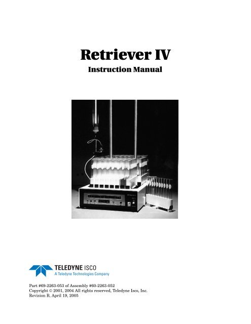
<strong>Retriever</strong> <strong>IV</strong>Instruction <strong>Manual</strong>Part #69-2263-053 of Assembly #60-2263-052Copyright © 2001, 2004 All rights reserved, Teledyne <strong>Isco</strong>, Inc.Revision B, April 19, 2005
ForewordThis instruction manual is designed to help you gain a thorough understanding of theoperation of the equipment. Teledyne <strong>Isco</strong> recommends that you read this manualcompletely before placing the equipment in service.Although Teledyne <strong>Isco</strong> designs reliability into all equipment, there is always the possibilityof a malfunction. This manual may help in diagnosing and repairing the malfunction.If the problem persists, call or email the Teledyne <strong>Isco</strong> Customer Service Departmentfor assistance. Contact information is provided below. Simple difficulties can often bediagnosed over the phone. If it is necessary to return the equipment to the factory forservice, please follow the shipping instructions provided by the Customer ServiceDepartment, including the use of the Return Authorization Number specified. Besure to include a note describing the malfunction. This will aid in the promptrepair and return of the equipment.Teledyne <strong>Isco</strong> welcomes suggestions that would improve the information presented inthis manual or enhance the operation of the equipment itself.Teledyne <strong>Isco</strong> is continually improving its products and reserves the right tochange product specifications, replacement parts, schematics, and instructionswithout notice.Contact InformationPhone: (800) 228-4373 (USA, Canada, Mexico)(402) 464-0231 (Outside North America)Repair Service: (800) 775-2965 (Analytical and ProcessMonitoring Instruments)(800) 228-4373 (Samplers and Flow Meters)Fax: (402) 465-3022Email address: info@isco.comWebsite: www.isco.comReturn equipment to: 4700 Superior Street, Lincoln, NE 68504-1398Other correspondence: P.O. Box 82531, Lincoln, NE 68501-2531Revised June 24, 2004
<strong>Retriever</strong> <strong>IV</strong> <strong>Fraction</strong> <strong>Collector</strong>SafetyGeneral Warnings<strong>Retriever</strong> <strong>IV</strong> <strong>Fraction</strong> <strong>Collector</strong>Before installing, operating, or maintaining this equipment, it isimperative that all hazards and preventive measures are fullyunderstood. While specific hazards may vary according to locationand application, take heed in the following general warnings:WARNINGLiquids associated with this instrument may be classifiedas carcinogenic, biohazard, flammable, or radioactive.Should these liquids be used, it is highly recommended thatthis application be accomplished in an isolatedenvironment designed for these types of materials inaccordance with federal, state, and local regulatory laws,and in compliance with your company’s chemical/hygieneplan in the event of a spill.AVERTISSEMENTWARNINGEviter de répandre des liquides dangereux. Les liquides quisont analysés dans cet instrument peuvent êtrecancérigènes, hasards biologiques, inflammables, ouradioactifs. Si vous devez utiliser tels liquides, il est trèsrecommandé que vous le faites à l'intérieur d'unenvironnement isolé conçu pour tels liquides. Cetenvironnement isolé devrait être construit selon lesrèglements fédéraux, provinciaux, et locaux, aussi que leplan de votre compagnie qui concerne l'évènement d'unaccident avec les matières hasardeuses.WARNINGAvoid hazardous practices! If you use this instrument inany way not specified in this manual, the protectionprovided by the instrument may be impaired.WARNINGAVERTISSEMENTÉviter les usages périlleux! Si vous utilisez cet instrumentd’une manière autre que celles qui sont specifiées dans cemanuel, la protection fournie de l’instrument peut êtreaffaiblie; cela augmentera votre risque de blessure.i
<strong>Retriever</strong> <strong>IV</strong> <strong>Fraction</strong> <strong>Collector</strong>SafetyWARNINGIf this system uses flammable organic solvents, Teledyne<strong>Isco</strong> recommends that you place this system in awell-ventilated environment, designed for these types ofmaterials. This environment should be constructed inaccordance with federal, state, and local regulations. Itshould also comply with your organization’s planconcerning chemical and hygiene mishaps. In all cases usegood laboratory practices and standard safety procedures.AVERTISSEMENTWARNINGCe système peut utiliser des dissolvants organiquesinflammables. Pour réduire le péril qui peut être causé parl'accumulation des vapeurs explosives, Teledyne <strong>Isco</strong>recommande que vous installez ce système dans unenvironnement bien-aéré qui est conçu pour les matièreshasardeuses. Cet environnement devrait être construitselon les règlements fédéraux, provinciaux, et locaux.Aussi, il devrait se conformer au plan de votre organisationqui concerne les mésaventures de l'hygiène ou dechimique. En tout cas, utilisez toujours de pratiquesbonnes de la laboratoire et des procédures standardes dela sûreté.Hazard Severity LevelsThis manual applies Hazard Severity Levels to the safety alerts,These three levels are described in the sample alerts below.CAUTIONCautions identify a potential hazard, which if not avoided, mayresult in minor or moderate injury. This category can also warnyou of unsafe practices, or conditions that may cause propertydamage.WARNINGWarnings identify a potentially hazardous condition, whichif not avoided, could result in death or serious injury.DANGERDANGER – limited to the most extreme situationsto identify an imminent hazard, which if notavoided, will result in death or serious injury.ii
<strong>Retriever</strong> <strong>IV</strong> <strong>Fraction</strong> <strong>Collector</strong>SafetyHazard SymbolsWarnings and CautionsThe equipment and this manual use symbols used to warn ofhazards. The symbols are explained below.Hazard SymbolsThe exclamation point within the triangle is a warning sign alerting you ofimportant instructions in the instrument’s technical reference manual.The lightning flash and arrowhead within the triangle is a warning sign alertingyou of “dangerous voltage” inside the product.Symboles de sécuritéCe symbole signale l’existence d’instructions importantes relatives au produitdans ce manuel.Ce symbole signale la présence d’un danger d’électocution.Warnungen und VorsichtshinweiseDas Ausrufezeichen in Dreieck ist ein Warnzeichen, das Sie daraufaufmerksam macht, daß wichtige Anleitungen zu diesem Handbuchgehören.Advertencias y PrecaucionesDer gepfeilte Blitz im Dreieck ist ein Warnzeichen, das Sei vor “gefährlichenSpannungen” im Inneren des Produkts warnt.Esta señal le advierte sobre la importancia de las instrucciones del manualque acompañan a este producto.Esta señal alerta sobre la presencia de alto voltaje en el interior delproducto.iii
<strong>Retriever</strong> <strong>IV</strong> <strong>Fraction</strong> <strong>Collector</strong>Safetyiv
<strong>Retriever</strong> <strong>IV</strong> <strong>Fraction</strong> <strong>Collector</strong>Table of ContentsTable of ContentsSection 1 Introduction1.1 Description. . . . . . . . . . . . . . . . . . . . . . . . . . . . . . . . . . . . . . . . . . . . . . . . . . . . . . . . . 1-11.2 Technical Specifications . . . . . . . . . . . . . . . . . . . . . . . . . . . . . . . . . . . . . . . . . . . . . . 1-1Section 2 Installation2.1 Unpacking . . . . . . . . . . . . . . . . . . . . . . . . . . . . . . . . . . . . . . . . . . . . . . . . . . . . . . . . . 2-12.2 Set Up . . . . . . . . . . . . . . . . . . . . . . . . . . . . . . . . . . . . . . . . . . . . . . . . . . . . . . . . . . . . 2-12.3 Preliminary Checkout . . . . . . . . . . . . . . . . . . . . . . . . . . . . . . . . . . . . . . . . . . . . . . . . 2-3Section 3 Operating Procedures3.1 Selecting the Operational Mode . . . . . . . . . . . . . . . . . . . . . . . . . . . . . . . . . . . . . . . . 3-13.2 Setting the Time/Count Switch . . . . . . . . . . . . . . . . . . . . . . . . . . . . . . . . . . . . . . . . 3-13.3 Setting the Scaling Switch . . . . . . . . . . . . . . . . . . . . . . . . . . . . . . . . . . . . . . . . . . . . 3-13.4 Programming Examples . . . . . . . . . . . . . . . . . . . . . . . . . . . . . . . . . . . . . . . . . . . . . . 3-23.5 Stop Rack . . . . . . . . . . . . . . . . . . . . . . . . . . . . . . . . . . . . . . . . . . . . . . . . . . . . . . . . . . 3-23.6 Drop Counter . . . . . . . . . . . . . . . . . . . . . . . . . . . . . . . . . . . . . . . . . . . . . . . . . . . . . . . 3-23.7 Flow Diverter Funnel . . . . . . . . . . . . . . . . . . . . . . . . . . . . . . . . . . . . . . . . . . . . . . . . 3-43.8 Internal Drip Pan . . . . . . . . . . . . . . . . . . . . . . . . . . . . . . . . . . . . . . . . . . . . . . . . . . . 3-43.9 Case Top . . . . . . . . . . . . . . . . . . . . . . . . . . . . . . . . . . . . . . . . . . . . . . . . . . . . . . . . . . 3-43.10 Valves. . . . . . . . . . . . . . . . . . . . . . . . . . . . . . . . . . . . . . . . . . . . . . . . . . . . . . . . . . . . 3-43.11 Connection to a Teledyne <strong>Isco</strong> Absorbance Detector. . . . . . . . . . . . . . . . . . . . . . . 3-73.12 Connection to a Computer or other External Controller . . . . . . . . . . . . . . . . . . . 3-83.13 Connection to a Teledyne <strong>Isco</strong> Wiz Peristaltic Pump . . . . . . . . . . . . . . . . . . . . . . 3-83.14 Masts . . . . . . . . . . . . . . . . . . . . . . . . . . . . . . . . . . . . . . . . . . . . . . . . . . . . . . . . . . . . 3-93.15 Racks . . . . . . . . . . . . . . . . . . . . . . . . . . . . . . . . . . . . . . . . . . . . . . . . . . . . . . . . . . . 3-103.16 Dust Cover . . . . . . . . . . . . . . . . . . . . . . . . . . . . . . . . . . . . . . . . . . . . . . . . . . . . . . . 3-113.17 Four Column Adapter . . . . . . . . . . . . . . . . . . . . . . . . . . . . . . . . . . . . . . . . . . . . . . 3-113.18 LC Organizing Shelf . . . . . . . . . . . . . . . . . . . . . . . . . . . . . . . . . . . . . . . . . . . . . . . 3-13Section 4 Theory of Operation4.1 Circuit Descriptions . . . . . . . . . . . . . . . . . . . . . . . . . . . . . . . . . . . . . . . . . . . . . . . . . 4-14.1.1 Timing Diagram . . . . . . . . . . . . . . . . . . . . . . . . . . . . . . . . . . . . . . . . . . . . . . . 4-4Section 5 Maintenance5.1 Introduction . . . . . . . . . . . . . . . . . . . . . . . . . . . . . . . . . . . . . . . . . . . . . . . . . . . . . . . . 5-15.2 Exterior Cleaning . . . . . . . . . . . . . . . . . . . . . . . . . . . . . . . . . . . . . . . . . . . . . . . . . . . 5-15.3 Case Top Removal . . . . . . . . . . . . . . . . . . . . . . . . . . . . . . . . . . . . . . . . . . . . . . . . . . . 5-15.4 Sensors. . . . . . . . . . . . . . . . . . . . . . . . . . . . . . . . . . . . . . . . . . . . . . . . . . . . . . . . . . . . 5-25.4.1 Cleaning Sensor Windows . . . . . . . . . . . . . . . . . . . . . . . . . . . . . . . . . . . . . . . 5-25.4.2 Electrical Adjustment of Sensors . . . . . . . . . . . . . . . . . . . . . . . . . . . . . . . . . 5-25.4.3 Sensor Assembly Replacement . . . . . . . . . . . . . . . . . . . . . . . . . . . . . . . . . . . 5-35.5 Shuttle Adjustment. . . . . . . . . . . . . . . . . . . . . . . . . . . . . . . . . . . . . . . . . . . . . . . . . . 5-5v
<strong>Retriever</strong> II <strong>Fraction</strong> <strong>Collector</strong>Table of Contents5.5.1 Shuttle Removal . . . . . . . . . . . . . . . . . . . . . . . . . . . . . . . . . . . . . . . . . . . . . . .5-55.6 Shuttle Timing Procedure . . . . . . . . . . . . . . . . . . . . . . . . . . . . . . . . . . . . . . . . . . . . .5-55.7 Converting to a Different Line Voltage or Frequency . . . . . . . . . . . . . . . . . . . . . . .5-85.8 Replacing the Motor . . . . . . . . . . . . . . . . . . . . . . . . . . . . . . . . . . . . . . . . . . . . . . . . . .5-85.9 Technical Troubleshooting . . . . . . . . . . . . . . . . . . . . . . . . . . . . . . . . . . . . . . . . . . . . .5-85.10 Integrated Circuits . . . . . . . . . . . . . . . . . . . . . . . . . . . . . . . . . . . . . . . . . . . . . . . . . .5-95.11 Service Department . . . . . . . . . . . . . . . . . . . . . . . . . . . . . . . . . . . . . . . . . . . . . . . .5-135.12 How to Ship Returns . . . . . . . . . . . . . . . . . . . . . . . . . . . . . . . . . . . . . . . . . . . . . . .5-135.13 Purchasing Parts . . . . . . . . . . . . . . . . . . . . . . . . . . . . . . . . . . . . . . . . . . . . . . . . . .5-13Appendix A Replacement PartsA.1 Overview. . . . . . . . . . . . . . . . . . . . . . . . . . . . . . . . . . . . . . . . . . . . . . . . . . . . . . . . . . A-1List of Figures1-1 Front Panel Controls and Indicators . . . . . . . . . . . . . . . . . . . . . . . . . . . . . . . . . . . .1-21-2 Rear Panel Connectors . . . . . . . . . . . . . . . . . . . . . . . . . . . . . . . . . . . . . . . . . . . . . . .1-32-1 Drop Counter Installation . . . . . . . . . . . . . . . . . . . . . . . . . . . . . . . . . . . . . . . . . . . . .2-22-2 <strong>Retriever</strong> II <strong>Fraction</strong> <strong>Collector</strong> . . . . . . . . . . . . . . . . . . . . . . . . . . . . . . . . . . . . . . . . .2-33-1 Test Tube Positioner - 18 mm tubes . . . . . . . . . . . . . . . . . . . . . . . . . . . . . . . . . . . . .3-33-2 Diverter Funnel . . . . . . . . . . . . . . . . . . . . . . . . . . . . . . . . . . . . . . . . . . . . . . . . . . . . .3-53-3 Tubing Connections . . . . . . . . . . . . . . . . . . . . . . . . . . . . . . . . . . . . . . . . . . . . . . . . . .3-63-4 Monitor Plug Pin Designation . . . . . . . . . . . . . . . . . . . . . . . . . . . . . . . . . . . . . . . . .3-83-5 Mast Installation . . . . . . . . . . . . . . . . . . . . . . . . . . . . . . . . . . . . . . . . . . . . . . . . . . .3-103-6 Available Tube Racks . . . . . . . . . . . . . . . . . . . . . . . . . . . . . . . . . . . . . . . . . . . . . . .3-103-7 Positioning the Four Column Adapter with Diverter . . . . . . . . . . . . . . . . . . . . . .3-123-8 Four Column Adapter with Diverter Actuated . . . . . . . . . . . . . . . . . . . . . . . . . . .3-123-9 LC Organizing Shelf . . . . . . . . . . . . . . . . . . . . . . . . . . . . . . . . . . . . . . . . . . . . . . . .3-134-1 Block Diagram . . . . . . . . . . . . . . . . . . . . . . . . . . . . . . . . . . . . . . . . . . . . . . . . . . . . . .4-34-2 Timing Diagram . . . . . . . . . . . . . . . . . . . . . . . . . . . . . . . . . . . . . . . . . . . . . . . . . . . . .4-55-1 Circuit Board Test Points . . . . . . . . . . . . . . . . . . . . . . . . . . . . . . . . . . . . . . . . . . . . .5-35-2 Case Top Diagram . . . . . . . . . . . . . . . . . . . . . . . . . . . . . . . . . . . . . . . . . . . . . . . . . . .5-45-3 Shuttle Timing Diagram . . . . . . . . . . . . . . . . . . . . . . . . . . . . . . . . . . . . . . . . . . . . . .5-65-4 Near Tunnel Final Timing Position . . . . . . . . . . . . . . . . . . . . . . . . . . . . . . . . . . . . .5-75-5 Far Tunnel Timing Position . . . . . . . . . . . . . . . . . . . . . . . . . . . . . . . . . . . . . . . . . . .5-75-6 Diagrams and Tables, Integrated Circuits . . . . . . . . . . . . . . . . . . . . . . . . . . . . . . . .5-95-7 Diagrams and Tables, Integrated Circuits, continued . . . . . . . . . . . . . . . . . . . . .5-10List of Tables1-1 Technical Specifications . . . . . . . . . . . . . . . . . . . . . . . . . . . . . . . . . . . . . . . . . . . . . .1-11-2 Front Panel Controls and Indicators . . . . . . . . . . . . . . . . . . . . . . . . . . . . . . . . . . . .1-21-3 Rear Panel Connectors . . . . . . . . . . . . . . . . . . . . . . . . . . . . . . . . . . . . . . . . . . . . . . .1-33-1 Connection Cables . . . . . . . . . . . . . . . . . . . . . . . . . . . . . . . . . . . . . . . . . . . . . . . . . . .3-73-2 Functions and Related Wire Connections . . . . . . . . . . . . . . . . . . . . . . . . . . . . . . . .3-83-3 Available Rack Set for <strong>Retriever</strong> II . . . . . . . . . . . . . . . . . . . . . . . . . . . . . . . . . . . .3-105-1 Symptom/Remedy Chart Technical Troubleshooting . . . . . . . . . . . . . . . . . . . . . .5-115-2 Rear Panel Connector Pin Descriptions . . . . . . . . . . . . . . . . . . . . . . . . . . . . . . . . .5-12vi
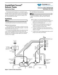
<strong>Retriever</strong> <strong>IV</strong> <strong>Fraction</strong> <strong>Collector</strong>Section 1 Introduction1.1 Description The <strong>Retriever</strong> <strong>IV</strong> is a fraction collector designed for column liquidchromatography, HPLC, and other applications involving measuredcollection of fractions. <strong>Fraction</strong>s can be collected on thebasis of time (0.1 to 999 minutes), counted drops (1 to 9990drops) or other counted events (1-9990) such as volumeter dischargesor electronic pulses from a peristaltic pump. Maximumtube capacity is 190 (10-18 mm) tubes or (17 mm) vials, or 133(28 mm) vials or (25 mm) tubes. The <strong>Retriever</strong> <strong>IV</strong> operates satisfactorilyin a coldroom, as well as at ordinary temperatures.Figure 1-1 <strong>Retriever</strong> <strong>IV</strong> <strong>Fraction</strong> <strong>Collector</strong>1-1
<strong>Retriever</strong> <strong>IV</strong> <strong>Fraction</strong> <strong>Collector</strong>Section 1 Introduction1.2 TechnicalSpecificationsTable 1-1 details the instrument’s technical specifications. Tables1-2 and 1-3 and Figures 1-2 and 1-3 explain the controls and connectorson the front and rear of the instrument.Power Requirements(Mains voltage line cord is a disconnectdevice.)Line frequencyLine Voltage Noise ToleranceDimensionsWeightCollection BasisEvent Mark OutputCount InputTube CapacityTube Change TimeLast Tube of Rack to First Tube ofNext RackAmbient Temperature RangeHumidityTube Change InputMaximum AltitudePollution Degree 2Installation CategoryTable 1-1 Technical Specifications100 ± 10 VAC, .4 Amps maximum117 ± 12 VAC, .4 Amps maximum234 ± VAC, .25 Amps maximum50 Hz or 60HzNote: Nominal line frequency is internally selectable and field convertible.1.7 x nominal rms line voltage, 10 microsecond pulses, any phase angle, randomor repetitive.12.6 inches wide x 4.00 inches high (to bottom of test tube) x 23.8 inches long(32 cm x 10 cm x 61cm)27 lbs. (12.25 kg)0.1 minute to 99.9 minutes in 0.1 minute increments1 minute to 999 minutes in 1 minute increments1 drop or volume to 999 drops or volumes in 1 drop or volume increments10 drops or volumes to 9990 drops or volumes in 10 drop or volume incrementsOpen collector which turns on to indicate a tube change and rack change (seeTable 5-2 - monitor jack)CMOS or TTL logic “0” for one msec minimum, one second maximum or onemsec to one second contact closure, or drop counter. Maximum repetition rate 4counts/second.190 (10-18 mm tubes or 17 mm vials)133 (28 mm scintillation vials or 25 mm tubes)0.30 second with 10 position rack0.45 second with 7 position rack0.80 second with 10 position rack0.75 second with 7 position rack0° C to 40° C95% maximumOpen collector TTL logic “0”, or contact closure for 22 msec minimum(see Table 5-2 - monitor jack)2000 mII}Factory Set1-2
<strong>Retriever</strong> <strong>IV</strong> <strong>Fraction</strong> <strong>Collector</strong>Section 1 Introduction8 9 10 11 122 3 4 5 6 7Figure 1-2 Front Panel Controls and Indicators1Table 1-2 Front Panel Controls and IndicatorsItem No.on Fig.1-2Control or Indicator Description Purpose1 Standby/Operate Rocker switch In the Standby position, power is applied to theanti-condensation heaters only.WarningAC mains voltage is present at all times inside the instrument. Alwaysdisconnect the unit from AC mains before removing the case top.In the Operate position, power is applied to the internalcircuitry instead of the heaters.2 Pause/Run Slide switch Allows the fraction collector to be stopped temporarilyduring collection or while collecting the void volumewithout erasing the tube totals.3 Void Vol Push button Activates the void volume feature which diverts flowfrom the collection tubes via an optional valve.4 Time/Vol/Drop Slide switch This switch selects whether the fraction size will bebased on minutes, drops, or volume units.5 Time/Count Thumbwheel switches These three switches allow you to select the size offraction collected.6 X1/X10 Drops/Min Slide Switch Multiples the Time/Count thumbwheel switches by afactor of 1 or 10.7 Advance Push button Advances the fraction collector and rests the countingcircuits.8 Units LED Display Displays the total number of units (X1 or X10) collectedin the tube at the collection station.9 Void Vol Red LED Indicates the initial void volume is being diverted towaste.10 Delay Timer (Sec) Thumbwheel switches Sets a delay time in seconds for synchronized peak collectionwith an accessory peak detector.11 Delay Red LED Indicates the delay timer is running.12 Tubes LED Display Displays total number of tubes that have completed collection.1-3
<strong>Retriever</strong> <strong>IV</strong> <strong>Fraction</strong> <strong>Collector</strong>Section 1 Introduction5 678124Figure 1-3 Rear Panel Connectors3ItemNo. onFig. 1-3Table 1-3 Rear Panel ConnectorsConnector Description Mating Connector Function1 Power 3-pin male plug manufacturedper IEC recommendations*--2 Pump 3-pin Jones Plug Beau ®S-303-CCT3 Outlet OverflowOverflow outlet4 Count 6 pin polarized Jonessocket7/16” OD tubingBeau ®P-3306-8-CCT-03Provides for connection to 100/117/234VAC 50/50HzInterface connection to shut off pump atend of a run.Provides route for overflow.Interface connection to a Teledyne <strong>Isco</strong>drop detector assembly or pump.Allows <strong>Retriever</strong> <strong>IV</strong> to count deliveriesor to shut off a pump while tubes arechanging and at the end of a run.5 Racks/tube Slide Switch -- This switch selects whether the unit willchange one tube at a time, or one rackat a time (for multi-source collections).6 Circuitbreaker 1.0A100 and 117VAC, 0.5A234 VACResettable circuit breaker(only one is installed for100 or 117 volt operation)7 Monitor 15-pin Sub-D socket CinchDA-15P8 Valve 2-Pin Jones Socket CinchP-302-CCT* For detailed pinout descriptions of these connectors, refer to Table 5-2.Beau ® is a registered trademark of the Vernatron Corp.--Limits the monitor current drawn fromthe main power supply. Push to reset.Interface connector to aTeledyne <strong>Isco</strong>detector for automatic peak separationand event marking. For non-Teledyne<strong>Isco</strong> detectors, event mark signal only.Closes accessory valve while changingtubes, at the end of a run, or ifpower fails.1-4
<strong>Retriever</strong> <strong>IV</strong> <strong>Fraction</strong> <strong>Collector</strong>Section 2 Installation2.1 Unpacking After removing the unit and accessories from the shippingcarton, examine them for signs of shipping damage. Be sure nointernal parts have shaken loose in transit. If there is anyshipping damage, file a claim with the delivering carrier immediately.Check the contents of the shipment against the packing slip. Ifthere are any shortages, notify Teledyne <strong>Isco</strong> immediately.NoteSave the packing materials and shipping carton until you aresure that all parts have been accounted for and the Instrumentis working satisfactorily.2.2 Set Up 1. The <strong>Retriever</strong> <strong>IV</strong> is shipped with the test tube racksinstalled. Because the test tube racks may have becomeloose during shipment, each rack should be pressed downfirmly to secure it to its shuttle. If the automatic stop featureof the <strong>Retriever</strong> <strong>IV</strong> is not to be used, the red stop testtube rack should be replaced with the white test tube rackin the accessory package.2. Remove the plastic covering from the rack sensor and supportrod assembly. Mount the sensor and support rodassembly (Figures 2-1 and 3-2) to its mounting holes on theleft side of the case top with the knurled thumbscrew.3. Remove the drop counter from the plastic bag, and mountit on the support rod so that appropriately sized tubes willpass under it unobstructed. This is done by loosening thelocking screw on the back of the drop counter assembly,positioning the entire assembly, then retightening the lockingscrew (see Figure 2-1).4. Install a black lead (tubing) connector (60-0928-001) intothe red drop former. The black lead connectors use ferrulesfor 1/16” or 1/8” OD tubing. Also included in the accessorypackage are white connectors (60-0573) which can be usedwith flexible inlet tubing.5. Next, plug the drop counter into the six-pin COUNT socketon the back panel. Final adjustment of the drop countingassembly will be necessary immediately prior to initiatingfraction collection.2-1
<strong>Retriever</strong> <strong>IV</strong> <strong>Fraction</strong> <strong>Collector</strong>Section 2 Installation6. Install two stainless steel masts onto the threaded connectorsin the center of the fraction collector. A second pair ofmasts can be added by first attaching the threaded couplersprovided. The masts can be used for mounting chromatographiccolumns, or other accessories such as valves,optical units, and pumps. An optional tray accessory(68-1564-046) attaches to the masts and provides a storagearea above the collection deck.7. Connect a piece of 7/16” OD flexible tubing to the outlet ofthe internal overflow tray (a 6” piece is provided in theaccessory package).8. Plug the power cord into the fraction collector and theninto a mains outlet. (Refer to Section 5.6 for instructions onchanging the operating voltage of the fraction collector.)MastsLockingScrewDropCounterSupport RodThumbscrewFigure 2-1 Rack sensor and drop counter attachment2-2
<strong>Retriever</strong> <strong>IV</strong> <strong>Fraction</strong> <strong>Collector</strong>Section 2 Installation2.3 Preliminary Checkout Proceed with the following steps:1. Set the Standby/Operate switch to Standby.2. Set the Time/Vol/Drop switch to the Time position.3. Set the 1 Drop/.1 Min switch to the X1 position.4. Set the Time/Count thumbwheel switches to 001.5. Set the Pause/Run switch to Run.6. Set the Delay Timer (Sec) thumbwheel switches to 000.7. Set the Standby/Operate switch to Operate. The red LEDswill come on and the <strong>Retriever</strong> II will advance one tube.The <strong>Retriever</strong> <strong>IV</strong> should then begin indexing through its tubepositions at six second intervals. Check to be sure it stops automaticallyafter the last tube of the red colored rack.If this preliminary test was unsuccessful in any way, contact theTeledyne <strong>Isco</strong> Service Department. Contact information can befound at the front of this manual.2-3
<strong>Retriever</strong> <strong>IV</strong> <strong>Fraction</strong> <strong>Collector</strong>Section 3 Operating Procedures3.4 ProgrammingExamplesBelow we have outlined some simple programming examples.1. Collection by time – Set the mode switch to TIME. If thedesired time interval between tube changes is 3.4 minutes,set the 1 DROP/.l MIN switch to the Xl position, and theTIME/COUNT switches to 034.2. Collection by drop – Set the mode switch to DROP. If thedesired number of drops per tube is 150, set the 1 DROP/.lMIN switch to the Xl position and the TIME/COUNTswitches to 150. Ensure that the drop counter assemblycable is plugged into the COUNT connector on the rearpanel.3. Collection by volume – Set the mode switch to VOL. If 3ml fractions are desired, and a Teledyne <strong>Isco</strong> volumeter isused, set the 1 DROP/.l MIN switch to the Xl position andthe TIME/COUNT switches to 001. Adjust the volumeter for3 ml collection.3.5 Stop Rack The red stop rack is used to program the automatic shutofffeature of the <strong>Retriever</strong> <strong>IV</strong>. The last test tube position of this rackhas special coding molded into the side. When this special codingis encountered at the rack sensor and tube filling location, thefraction collector stops changing tubes, shuts off an attachedpump, or an optional valve will divert the flow away from the collectionarea.The final position of the stop rack provides a signal to the rearpanel connectors which will stop a pump or fractionator, oractivate a valve, and the fraction collector will no longer respondto tube advance signals from a peak separator. To use the stoprack, determine the number of fractions desired, count back in aclockwise direction to that number, and replace the white rack atthat position with the red stop rack.3-2
<strong>Retriever</strong> <strong>IV</strong> <strong>Fraction</strong> <strong>Collector</strong>Section 3 Operating ProceduresFigure 3-1 Tubing connections3-3
<strong>Retriever</strong> <strong>IV</strong> <strong>Fraction</strong> <strong>Collector</strong>Section 3 Operating Procedures3.6 Drop Counter Refer to Figure 3-1 for tubing connector selections. Two tubingconnector are supplied for the drop counter. A black tubing connector(60-0928-001) is to be used for 1/16” or 1/8” plastic, glass,or steel tubing. An optional white connector (60-0573-128) isincluded for use with flexible plastic tubing. The drop countercan be adjusted forward and backward by using the positioningscrew (Figure 3-2). Adjustment may be necessary to ensure thatthe drops fall cleanly into the collection tubes.Support RodTubing ConnectorDrop CounterColumn BracketPostioning ScrewSpring andWasherDrip ShieldThumbscrewRack SensorFigure 3-2 Drop counter adjustment3-4
<strong>Retriever</strong> <strong>IV</strong> <strong>Fraction</strong> <strong>Collector</strong>Section 3 Operating Procedures3.7 Void Volume Feature The <strong>Retriever</strong> <strong>IV</strong> includes a void volume feature which workswith an optional diverter valve (P/N 68-2177-002) to divert aninitial volume to waste prior to starting collection. This divertedvolume usually represents the column void volume which precedesany separations. But, the diverted volume can include boththe void and any unwanted eluent during the initial part of theseparation.The void volume feature has two distinct application advantages:1. It can be used to reduce clean up and glassware use byallowing collection in fewer tubes.2. It can effectively increase the capacity of the fraction collectorby allowing the diversion of an initial volume towaste.In operation, the void volume feature diverts flow via an optionaldiverter valve while the tubes and racks advance in normalfashion on the <strong>Retriever</strong> <strong>IV</strong>. When the end of the red rack passesunder the drop counter, the void volume diversion end and flow isdirected into the first tube after the red rack. The diversionvolume is set by the starting position of the red rack. Thediverted volume equals the programmed volume per collectingtube times the number of tubes from the starting point (after thePAUSE/RUN switch is switched to RUN, the first tube will beadvanced) to the last tube before the first tube of the red rack.Unlike normal collection, when the void volume feature is used,the red rack does not stop the collector until its second passunder the drop counter. On its first pass, the red rack stops thevoid diversion by switching the diverter valve from waste to collectionand the movement of the racks continues in a normalfashion until the last position of the red rack is encountered asecond time.NoteIn the TIME and VOL. modes, the void volume is measured bystandard means (minute counting or volumetric pump control).But when fractions are collected in the drop count mode, thevoid volume feature translates the programmed fraction dropcount into tenths of minutes during the void diversion. Forexample, if the fraction collector is programmed for 75 dropfractions during the void volume diversion, the collector willadvance tubes every 7.5 minutes. The void volume incrementper tube would be equal to the flow rate in ml/min times 7.5minutes. Once the void diversion is ended, the collector willresume normal drop counting. The void volume diversion featurecannot be used in conjunction with a Teledyne <strong>Isco</strong> volumeter.3-5
<strong>Retriever</strong> <strong>IV</strong> <strong>Fraction</strong> <strong>Collector</strong>Section 3 Operating ProceduresExamples: 1. Using a 10-position rack, the <strong>Retriever</strong> <strong>IV</strong> is set to collect 5minute (10 ml) fractions and a 60 ml (30 minute) void volumediversion is needed. The fraction collector should bestarted on tube number 3 of the red rack. This leaves 6tubes, between the starting tube of the red rack and thelast tube (stop position) of the red rack. This will accommodate60 ml or 30 minutes of diversion before the first tubeof the white rack. Momentarily push the VOID/VOL. buttonand then slide the PAUSE/RUN switch to RUN, thenthe rack will advance to the next tube. A LED will indicatewhen the void volume collection is in progress.2. Using a 7-position rack, the <strong>Retriever</strong> <strong>IV</strong> is set to collect100 drop fractions per tube and an 80 minute diversion isneeded. The fraction collector should be started on thetenth tube from the last tube position of the red rack sothat eight vials pass under the drop counter before the firstwhite rack. The 100 drop setting will be counted as 100tenths of a minute (10.0 minutes) during diversion.Momentarily push the VOID VOL. button and then slidethe PAUSE/RUN switch to RUN. A LED will indicate whenvoid volume collection is in progress (see Figure 3-3).Figure 3-3 Void Volume DiversionExample of starting setup for void diversion: the vials markedwith an “X” will pass, unfilled, under the drop counter duringvoid diversion. With a programmed fraction time of ten minutes,the void diversion time will be 80 minutes and the volumediverted is equal to the flow rate in ml/min times 80 minutes.3-6
<strong>Retriever</strong> <strong>IV</strong> <strong>Fraction</strong> <strong>Collector</strong>Section 3 Operating Procedures3.8 Flow Diverter Funnel The flow diverter funnel (provided) is normally used in conjunctionwith the stop rack. When the last position of the stoprack has been encountered, the funnel diverts the effluent fromthe collection point. The diverter funnel should be attached to thedrop counter support rod (Figure 3-4) and positioned so that it isto the left of the collection point, and not disrupting themovement of test tubes advancing underneath it. Place a rubberstopper in the test tube in the last position of the red stop rack.Adjust the diverter funnel so that it will contact the rubberstopper when it advances toward the collection point. As the lasttube moves underneath the collection point, it will position thediverter funnel under the effluent stream, and divert it throughthe diverter drain hose. Some provisions should be made for collectingor disposing of the diverted waste.Figure 3-4 Diverter Funnel3-7
<strong>Retriever</strong> <strong>IV</strong> <strong>Fraction</strong> <strong>Collector</strong>Section 3 Operating Procedures3.9 Internal Overflow The <strong>Retriever</strong> <strong>IV</strong> contains a polypropylene overflow tray beneaththe racks and shuttles. This overflow tray is designed to divertspills to waste. An outlet is provided for attaching tubing. Theoutlet from the tray is designed to accept 7/16” OD tubing asshown in Figure 3-5. The volume of the internal overflow tray is1.5 liters.Bezel RetainingScrewsFront Edgeof TrayOverflowRetaining Nut7/16” OD TubingTransformerCoverFigure 3-5 Overflow TrayWARNINGDo not plug the overflow drain. If the drain is blocked, theoverflow could fill the tray. If the solvent is flammable,sparks from contacts inside the unit could ignite theaccumulation of overflow.3.10 Case Top The <strong>Retriever</strong> <strong>IV</strong>’s case top is designed to be easily removed forcleaning or convenient storage of samples. Simply release thefour case top latches and remove the sensor/drop formerassembly (refer to section 5.2).CAUTIONRisk of electric shock. Disconnect electric power before servicing.Only trained service personnel may remove the transformercover or the overflow tray.3.11 Valves Two solenoid-operated valves, which stop flow during tubechanges and at the end of the run are available as an option fromTeledyne <strong>Isco</strong>. These valves are made of Kel-F ® and Teflon ® , andare essentially inert. Similar valves (with different plugs and differentoperating voltages) are used on other Teledyne lscofraction collectors, so it is important to be sure you have thecorrect valve.These valves stop or divert effluent flow approximately 0.8seconds before each tube change. They will always stop or diverteffluent flow at the end of a run, and during power failure. Theyare especially recommended when working with radioactive or3-8
<strong>Retriever</strong> <strong>IV</strong> <strong>Fraction</strong> <strong>Collector</strong>Section 3 Operating Proceduresother hazardous effluents, because they help prevent drops fromfalling between tubes. A spring clip attaches the valve to the verticalmast. Compression fittings accept either 1 /16" (1.5 mm) or1 /8" (3 mm) OD plastic tubing.To connect the valves, plug the valve cable into the two-pinVALVE socket on the rear panel of the <strong>Retriever</strong> <strong>IV</strong>.1. Security Valve (P/N 68-2177-001) – This on-off valve isrecommended for operation at pressures below 30 psi. Useit in gravity flow and peristaltic pump systems.2. Diverter Valve (P/N 68-2177-002) – Instead of shuttingoff flow, this valve diverts it to a drain or receptacle. It istherefore suitable for higher pressure systems or applicationswhere the flow from the column should not beblocked. The valve connection labeled “IN” is the inlet. Theconnection labeled “WASTE” (normally open) goes to thedrain. The connection marked “COLLECT” (normallyclosed) goes to the fraction collector drop counter. Effluentflowing during tube changes is diverted and not collectedin any tube.3.12 Connection to aTeledyne <strong>Isco</strong>Absorbance DetectorThe information transmitted between the <strong>Retriever</strong> <strong>IV</strong> and aTeledyne <strong>Isco</strong> detector consists of tube change event marks,which appear as short negative blips, rack change event marks,which appear as short positive blips on the absorbance trace (noseparate pen is necessary), and a tube advance signal from anoptional peak separator which may be built into the detector. Thepeak separator circuit locates peaks by the change of slope in thedetector signal. At the beginning and end of each peak, the peakseparator signals the <strong>Retriever</strong> <strong>IV</strong> to change tubes, putting eachpeak into its own tubes with no dilution from preceding or succeedingbaseline effluent.NoteWhen superimposing the event mark on the absorbance curve,set the recorder baseline a little above zero. The event markblip hangs below the curve and cannot be made if the pen isalready at zero.V4 Variable Wavelength Detector or UA-6 –The V4 or UA-6 is connected to the <strong>Retriever</strong> <strong>IV</strong> with cable68-1020-213. The end of this cable with the 15-pin plug arrangedin two rows should be connected to the <strong>Retriever</strong> <strong>IV</strong>’s rear panelconnector labeled MONITOR. The other end of the cable, whichhas a nine-pin Sub D plug, should be connected to the detectorrear panel connector labeled FRACTION COLLECTORINPUT/OUTPUT.The effluent stream from the detector is then plumbed to either asecurity valve, diverter valve, or directly to the <strong>Retriever</strong> <strong>IV</strong> dropcounter.3-9
<strong>Retriever</strong> <strong>IV</strong> <strong>Fraction</strong> <strong>Collector</strong>Section 3 Operating ProceduresTable 3-1 <strong>Retriever</strong> <strong>IV</strong> Connection CablesPart Number Connection Function68-1010-103 Pumps or other instrumentsShuts off pump or other instrument with 1 amp or less at endof run.68-1020-159 TRIS pump Volumetric collection and shut off.68-1020-161 TRIS pump Pump shut off at the end of the run.68-1020-213 Current UA-6 and V 4 detectorMarks tube changes on chart recorder and provides peakseparator interface.68-1020-083 Teledyne <strong>Isco</strong> detector Recorder stop at the end of the run.68-1010-111 Non-Teledyne <strong>Isco</strong> detector External control by non-Teledyne <strong>Isco</strong> detector.68-1020-188 Valve Connects two valves3.13 Connection to aComputer or otherExternal ControllerThe <strong>Retriever</strong> <strong>IV</strong> may be controlled externally via the 15-pinMONITOR connector. The monitor plug is shown in Figure 3-6numbered as seen from the rear of the <strong>Retriever</strong> <strong>IV</strong>. The matingconnector is a Cinch DA-15P Sub D or equivalent. Further informationcan be found in Table 5-2.Cable 68-1010-111 can be used for interfacing with Teledyne <strong>Isco</strong><strong>Retriever</strong> <strong>IV</strong> fraction collectors. One end of this cable has a15-pin connector which connects to the MONITOR plug of the<strong>Retriever</strong> <strong>IV</strong> and the other end has 10 wires. The most commonapplication involves remote control of fraction changes, but thiscable also provides connections for sending tube change eventmarks to the recording instrument being used. The function andrelated wire connections are described in Table 3-2.The <strong>Retriever</strong> <strong>IV</strong> will advance one tube position upon receipt of acontact closure across pins 2 (+12 VDC) and 9 (circuit common).This signal must be 22 milliseconds or greater in duration toadvance tube positions.NotePin 2 has +12 VDC in reference to circuit common, therefore itis not TTL compatibleFigure 3-6 Monitor Plug Pin Designation3-10
<strong>Retriever</strong> <strong>IV</strong> <strong>Fraction</strong> <strong>Collector</strong>Section 3 Operating ProceduresTable 3-2 Connector Pin DescriptionPin Wire Color Use1 Red +12 Volts2 Brown External tube change input5 Yellow Tube changing event mark6 Orange External pause8 Green Earth9 White Common11 Blue Motor Stop12 Black Valve13 Violet Pause count14 Grey End of run output3.14 Connection to TRISPumpsExample:3.15 Connection toNon-Teledyne <strong>Isco</strong>PumpsThe recommended cable for stopping the TRIS pump after the<strong>Retriever</strong> <strong>IV</strong> has completed its run is P/N 68-1020-161.An alternative cable connection to allow the fractions to be collectedvolumetrically from the TRIS pump is P/N 68-1020-159.With this connection, the TRIS pump sends electronic pulsesbased upon volume displaced to the fraction collector.The TRIS pump transmits at 267 pulses (open collector transistoroutput) per 10 revolutions of its rotor assembly. Thesepulses can be counted by <strong>Isco</strong> fraction collectors to allow collectionof fractions based upon fractions of pump revolutions. Setthe count switches to the desired volume to be pumped to eachfraction collector tube (1 ml is approximately 22 counts with 1/8"ID tubing; 78 counts with 1/16" ID tubing). Allow the pump tooperate at the selected speed for approximately 30 minutes towear in the tubing. Connect the pump to the fraction collector,measure the fluid pumped, then adjust the count in the fractioncollector to the desired accuracy. This step is necessary, since theID of standard silicone tubing can vary as much as 10%.<strong>Fraction</strong>s of 5 ml are required and the pump is found to dispense1.21 ml per rotor revolutions, or 5 ml in 4.56 revolutions. At 267pulses per 10 rotor assembly revolutions, TRIS will send out 110pulses for each 5 ml pumped (22 pulses/ml with 1/8" tubing). Byprogramming the fraction collector to collect 110 units in thevolume mode, 5 ml fractions will be collected.When a non-Teledyne <strong>Isco</strong> pump is used, a cable is used tointerrupt mains power to the pump after the last tube has beenfilled. For pumps operating on 117 Vac at 1 amp or less, cable P/N68-1010-103 is used.3-11
<strong>Retriever</strong> <strong>IV</strong> <strong>Fraction</strong> <strong>Collector</strong>Section 3 Operating Procedures3.16 Racks Three rack types are available for the <strong>Retriever</strong> <strong>IV</strong> (see Table 3-3and Figure 3-7). All racks have a stand, which can be rotated tosupport the rack when it is removed from the <strong>Retriever</strong> <strong>IV</strong>.Table 3-3 Available Rack Sets for the <strong>Retriever</strong> <strong>IV</strong>Part No. Tubes Accommodated Tubes per Rack <strong>Retriever</strong> <strong>IV</strong> Capacity68-0827-059 10 to 18 mm OD, 17 mm vials 10 190 tubes in 19 racks68-0827-060 25 mm OD 7 133 tubes in 19 racks68-0827-061 28 mm Scintillation vials 7 133 vials in 19 racks68-2187-00268-0827-05910 x 10 to 18 mm68-0827-0617 x 28 mm68-0827-0607 x 25 mmFigure 3-7 Available Tube Racks3.17 Multi-SourceCollection AdapterThe optional multi-source adapter (68-2267-001) is designed toallow collection of up to 19 fractions from as many as 10 chromatographiccolumns or other sources. 2.3.) The adapter (Figure3-8) serves as a tubing connection station for 7 inlets when 28mm scintillation vials are used, or for 10 inlets when 13, 16 or 18mm tubes are used. Special tubing connectors (P/N 60-2263-016)are supplied with the adapter to hold the tubing over the tubes orvials and serve as drop formers. These connectors use the sametubing ferrules as described in Figure 3-1.A rear panel switch (Figure 1-2) changes the operation of thefraction collector from stopping at each tube position in a rack tostopping only once per rack. The multi-source adapter may beinstalled over the rear or front racks of the collector. When thefraction collector advances to the next rack, the racks along therear of the collector move in one, approximately 0.8 second step.The advancement of the racks along the front of the collectoroccurs in two steps. The first requires approximately 0.7 secondsand accounts for approximately 80% of the total shiftingmovement and the remainder of the advancement occurs approx-3-12
<strong>Retriever</strong> <strong>IV</strong> <strong>Fraction</strong> <strong>Collector</strong>Section 3 Operating Proceduresimately 4 seconds later. For this reason, the adapter should normallybe mounted over the rear racks of the fraction collector asshown in Figure 3-8. When using 16 mm or larger tubes, theadapter can be aligned over the front racks and adjusted so thatdrops falling from both advancement steps fall into the tubes.Using the front position is detailed in the paragraphs describingthe use of two multi-source adapters at the end of this section.The flow diverter on the adapter can be used to direct flow awayfrom the fraction collector at the end of a run. The diverter has aspring loaded trough which swings into place when it encountersa rubber stopper placed in the last rack in the run. As shown inFigure 3-8, the trough swings into place and diverts flow into awaste vessel placed beside the collector.The following procedure should be used to set up themulti-source adapter over the rear racks.1. If not already in place, install the right stainless steel columnsupport mast and tighten firmly in place.2. Slide the multi-source adapter over the mast and temporarilytighten it so it extends out the rear of the unit as picturedin Figure 3-8.3. Loosen the four small thumbscrews on the side of theadapter. Connect the tubing from the multiple sources toeach of the special tubing connectors supplied, using thetubing ferrules as described in Figure 3-1. Using the markingson the top of the multi-source adapter as a guide,install the seven or ten tubing connectors in their properpositions (for use with seven or ten tube racks, respectively)and then tighten the four small thumbscrews on theside of the adapter to hold the tubing connectors in place.4. Set the PAUSE/RUN switch in the PAUSE position. Usinga screwdriver, or other pointed tool, set the rear panelRACKS/ TUBES switch to the RACKS position.5. Depress and hold the ADVANCE switch until the fractioncollector advances to the red stop rack and then release theswitch allowing the unit to stop at the final position of thered stop rack.3-13
<strong>Retriever</strong> <strong>IV</strong> <strong>Fraction</strong> <strong>Collector</strong>Section 3 Operating ProceduresFlow DiverterActuatorRubber Stopper TripsFlow DiverterRed Stop RackCollection RackFigure 3-8 Multi-Source AdapterNoteIf the flow diverter is not being used, remove the red stop rackand replace it with another white rack.6. Swing the flow diverter to the side of the adapter. Align themulti-source adapter over the second rack from the leftrear (collection rack, see Figure 3-8) such that the dropswill fall into the center of the tubes. Use the four largethumbscrews as shown in Figure 3-9 to adjust the heightand side-to-side movement of the adapter and hand tightenfirmly.7. If the flow diverter is being used, place a tube with a rubberstopper in the first tube position of the rack presentlyunder the multi-source adapter. This is the tube positionclosest to the center of the fraction collector. When the fractioncollector runs, this stopper will engage the actuatorthat extends below the flow diverter to swing the diverterinto place under the multiple drop formers. Place a collectionbeaker behind the collector to collect the divertedfluid.8. Make a final check to assure that the tubing connector outletsare properly aligned over the tubes or vials. Set thefraction collector to the TIME mode (the DROP mode is notused with the multi-source adapter) and set the collectiontime for the fractions. Set the PAUSE/RUN switch to RUN3-14
<strong>Retriever</strong> <strong>IV</strong> <strong>Fraction</strong> <strong>Collector</strong>Section 3 Operating Proceduresand depress the ADVANCE switch until the red rack clearsthe sensor position.If collection from more than ten sources is required, a secondmulti-source adapter may be added. When the second adapter isused, the <strong>Retriever</strong> <strong>IV</strong> is able to collect up to nine fractions persource.Follow this procedure when setting up two multi-sourceadapters.1. Remove the red stop rack from the fraction collector. Thered stop rack should not be used because it prevents thefinal stepped movement of the racks on the front of theunit.2. Follow steps 1 to 7 of the preceding procedure to align therear multi-source adapter.3. If not already in place, install the left stainless steel columnsupport mast and tighten firmly in place.4. Slide the second multi-source adapter over the left mastand temporarily tighten it so it extends out the front of thefraction collector.5. Install the tubing connectors in the front adapter asdescribed in step 3 of the preceding rear adapter procedure.6. Align the second multi-source adapter using the four largethumbscrews so that the drops will fall slightly to the leftof center of the second rack from the left front of the<strong>Retriever</strong> <strong>IV</strong>.7. If the flow diverters are being used, place a tube with arubber stopper in the last tube position of the rack presentlyunder the front adapter. This is the tube position inthe rack closest to the center of the fraction collector.Tubing ConnectorHolder ScrewsHeight AdjustmentScrewsSide-to-SideAdjustmentScrewsFigure 3-9 Overhead View of the Multi-Source Adapter3-15
<strong>Retriever</strong> <strong>IV</strong> <strong>Fraction</strong> <strong>Collector</strong>Section 3 Operating Procedures8. Make a final check to assure that the tubing connector outletsare properly aligned over the vials or tubes. It is a goodidea to use the ADVANCE switch to advance through acomplete run. When the fraction collector is advancing,make sure drops from both stopping positions of the frontracks fall into the tubes and the rubber stoppers properlyactivate the flow diverters.3.18 Optional Accessories The following accessories are available from Teledyne <strong>Isco</strong>.Table 3-4 Optional Accessories for use with <strong>Retriever</strong> <strong>IV</strong>68-2267-001 Multi-source collection adapter68-2177-001 Security valve, 12 volt60-2177-002 Diverter valve, 12 volt60-2267-00568-2267-006 Dust coverRecommended spare parts package, containing:1 each 69-2263-015 Motor1 each 60-1297-068 Sensor assembly6 each 60-0083-153 Black 1.5 mm ferrule6 each 60-0083-163 Natural 1.5 mm ferrule6 each 60-0923-017 Ferrule, 0.125 diameter1 each 60-2264-016 Drop detector2 each 69-1103-106 Drop counter sleeve1 each 130-0002-03 Seven segment LED display5 each 411-0322-70 Fuse, 3AG, 250 V, 3 amp1 each 279-0201-00 Integrated circuit, VR MC78051 each 279-0200-02 Integrated circuit, VR MC78121 each 270-0803-00 Integrated circuit, transistor array, 20031 each 411-9901-80 Fuse, 125 V, 1 amp picofuse68-0827-059 Test tube rack set, 18 mm68-0827-060 Test tube rack set, 25 mm68-0827-061 Vial rack set, 28 mm68-0827-053 Rack carrier tray68-1010-103 Connect cable to non-Teledyne <strong>Isco</strong> pump, 1 amp for pump shutoff at end of run68-1020-083 Connect cable to Teledyne <strong>Isco</strong> detectors for recorder shutoff at end of run68-1020-213 Connect cable to Teledyne <strong>Isco</strong> detectors68-1020-161 Connect cable to Teledyne <strong>Isco</strong> TRIS pump for pump shutoff at end of run only68-1020-159Connect cable to Teledyne <strong>Isco</strong> TRIS pump to count pump pulses and for pump shutoff betweentubes and at end of run68-2177-008 Manometer electrode assembly69-0313-001 1 ml aqueous siphon69-0313-002 1 ml low viscosity siphon290-0012-00 Clamp holder68-1010-111 Universal interface cable68-1020-188 2 valve connector68-2267-008 Label package3-16
<strong>Retriever</strong> <strong>IV</strong> <strong>Fraction</strong> <strong>Collector</strong>Section 4 Theory of OperationCAUTIONRisk of electric shock. Disconnect the electric power beforeservicing. Only trained service personnel may remove theoverflow tray or transformer cover.4.1 Circuit Descriptions Refer to the block diagram in Figure 4-1 and the schematic(available online) as needed when following the circuit descriptions.To view the schematic drawings for the <strong>Retriever</strong> <strong>IV</strong>, first findthe serial number for your unit. Then go to our Web site atwww.isco.com. Select Training and Support and then ProductSupport. Click on Liquid Chromatography Products and thenselect Schematics in the left margin. After you enter your serialnumber, you will be able to view the schematics online. If youneed any assistance, or don’t see the correct schematic for yourspecific unit, contact our service department.The power supply consists of an external transformer, afull-wave bridge rectifier, and an IC voltage regulator. Theoutputs supplied are a fused, filtered +16 V, regulated +12 V and+5V, and a frequency reference.The time base for the controller is derived by counting down theAC line frequency from the power supply (+18.9 V peak, halfsine) to the squaring amplifier (U112A) via a low pass RC filter.This squaring amplifier is an AND gate Schmitt trigger whichchanges the sine wave input to a square wave clock output. Thisclock signal is applied to the BCD counters of the time base(U110A, B, U111A). U110A, in turn, divides the clock signal byeither 5 or 6, depending on the setting of the 50–60 Hz jumper, toobtain a 10 Hz clock signal. The 10 Hz signal is then divided by10 in U110B, which obtains a 1 Hz signal for the delay timer. The1 Hz signal is divided by 6 (U111A) to produce a 0.167 Hz (10pulses/min) signal which is one of the two selectable inputs to thetime, volume, and drop control, U106 and S103. The other inputsource for the time, volume, and drop control is the externalcount input. In the case of the count input, the signal can beaccepted in one of three forms: drop sensor, open collector, orcontact closure. The drop sensor is a light emitting diode and aphoto transistor.They are placed so that falling drops block the light path to thephoto transistor. The photo transistor conductance is directlyproportional to the quantity of light falling on it. The count inputregulator (Q103) holds the current drawn by the photo transistor4-1
<strong>Retriever</strong> <strong>IV</strong> <strong>Fraction</strong> <strong>Collector</strong>Section 4 Theory of Operationconstant. When a drop falls between the LED and the photo transistorthe conductance of the photo transistor decreases therebycausing a signal to switch Q103 low. This low-going transition isfed to the monostable pulse shaper (U105) to provide an activelogic 1 output of approximately 180 msec duration.The pulse input is selected by the user with S103B, and isapplied to the time, volume, and drop control (U106). This outputgoes tot he time/count circuit (U109 and U117) and display unit(U120-U122) either directly or divided by 10 by U109A, asselected by the multiplier switch, Sl05.A +12 V supply from R172 to the commons of the BCD switches(S104) is held low through the BCD switches by the time/count(U109B, U117A, B). Once the preset number on the BCDswitches is reached by the counter, all the Q outputs will be at ahigh, then the delay timer will begin counting to its presetnumber, and subsequently signaling the motor to start.When a logic 1 is applied to the set input of the delay controlflipflop U114A, it forces the Q output of U114A to a logic 0 andthe Q output is a logic 1. The Q output will remain a logic 0 untila signal from the motor control flip-flop (U114B) gets set. WhenU114A Q goes low and Q goes high, it will send an event mark(through U108D, U123C, U103 and U102D) to the monitor jack(J9) and starts the delay timers (U111B, U401). Once the presetnumber on the delay timer BCD switches (S401) is reached bythe BCD counter (U111B, U401), all the Q outputs will be at alogic 1 level. This logic 1 level and the logic 1 level from the Q ofthe delay control flip-flop (U114A) will go to U112D to set themotor control flip-flop (U114B).When the motor control flip-flop (U114B) is set, the Q output willremain a logic 0 until a clocking signal is applied to pin 11. WhenQ of U114B goes low then U130B will be set, forcing the Q outputof U130B to a logic 0. When Q of U130B goes to a logic 0 thenU104G is turned off, the displayed tube number counter (U124)advances one and allows the voltage at pin 6 and 2 of U129 toincrease via the charging network of C132, R163, and R169. Normallythe resistor which actually charges C132 is R163, however,when switch S103A is in the DROP mode, the much smallerresistance of R169 allows the voltage at pin 6 and 2 of U129 toincrease at a much faster rate than if only R163 was used.Once the increasing voltage at pin 2 and 6 of U129 reachesapproximately 8 volts, the output at pin 3 of U129 is forced low,and turns off U104F which provides a logic 1 to the motor drive(Q1). Q101 will limit the current to the motor to prevent damagein case of a mechanical failure. The motor continues to run untilthe next test tube comes into position and the cycle sensornetwork (U127B) generates an output. The output from the cyclesensor network will reset the Q output of U114V to a logic 1state. The Q output of U114B will reset U130B and it’s Q outputturns on U104G which returns U129 output to a logic 1. Theoutput of U129 turns on U104E and F which stops the motor byturning off Q1 and simultaneously turning on Q102. Q102 isused to stop the motor quickly and consistently.4-2
<strong>Retriever</strong> <strong>IV</strong> <strong>Fraction</strong> <strong>Collector</strong>Section 4 Theory of OperationFigure 4-1 Block Diagram4-3
<strong>Retriever</strong> <strong>IV</strong> <strong>Fraction</strong> <strong>Collector</strong>Section 4 Theory of OperationWhen the void start button (S102) is pushed, it will reset the voidvolume flip-flops (U119), and forces the Q output of U119A high.When Q goes high, U102G is turned on, DS401 lights up, andsimultaneously the security valve circuit (U108A, U104C,U102A, B) will turn off the valve. The Q output will remain highuntil the red rack has passed the sensor and the next tubeposition is reached.The security valve has another input which comes from themotor control flip-flop (U114B) Q. This Q output is appliedthrough U107C to the security valve drive (U108A, U104C,U102A, B) and to the pump stop signal drive (U102F). As thefraction collector advances, the security valve drive U102A andU102B will provide an open collector output on pin 12 of themonitor jack (J9) and to pin 1 of the valve jack (J10) to turn on/offa security valve. U102F provides an open collector output on pin5 of the count jack (J8) to stop a pump during tube changes.The monitor jack (J9) provides both a rack and a tube eventmark and an external advance signal. The tube event mark iscreated by U103 and U102D on pin 5. Each time the fraction collectortime/count reaches the preset number and sets the delaycontrol flip-flop U114A, an event mark occurs. The rack eventmark signal is created by U104A on pin 4. Each time the fractioncollector changes to the next consecutive rack, an event markoccurs. An external advance signal can be created on pin 2 with acontact closure or open collector. This signal is inverted byU131A and applied through U130A to U114A in the samemanner as a pulse from the time/count BCD switches (S104),resulting in starting the delay time and then moving to the nexttube position.Other signals on the monitor jack are motor stop, end of run, andpause count signal. An external motor stop signal can be createdon pin 11 with an open collector. This signal will keep U130Breset and trigger U129, resulting in keeping the motor fromturning on and advancing to the next tube. The end of run signalis created on pin 14. This end of run signal will turn on an opencollector output (U102C) when the red stop rack is reached. Theexternal pause count signal can be created on pin 13 with anopen collector. This signal will go to U106A and keep any countsfrom getting to the BCD counters.When power is initially applied to the circuitry, a capacitor(C130) is charged through U123H. During the brief chargingtime U123H’s output reaches high. This high signal will gothrough U101C, U113A and D setting U114B resulting in anadvance of the tube by one position. This occurs when the unit isfirst switched to operate and whenever power is restored after aninterruption assuring that collection starts or resumes in anempty tube.If the unit is powered up and the rack is in the stop position, anRC network on pin 5 U115B prevents the fraction collector fromadvancing past the stop position.4-4
<strong>Retriever</strong> <strong>IV</strong> <strong>Fraction</strong> <strong>Collector</strong>Section 4 Theory of OperationWhen the last position on the red stop rack is reached, the outputof U127D will go low resetting the motor control flip-flop U114Bto stop the motor. In addition, the output of U115A will set theend of run flip-flop U128A. When U128A is set the Q output goeslow preventing any additional input counts on U105, also turningthe security valve output off, the pump stop output of the countconnector on, and operating the pump isolation relay K101. Thisresults in turning off any pumps connected to the fraction collectorand closing the security valve.4.1.1 Timing Diagram To illustrate the timing and relationship of signals during operation,selected waveforms are shown on the timing diagram,Figure 4-2. The timing diagram assumes the front panel switchesare set as shown below.TIME/COUNT - set at 001X1 /X10 - set XlTIME/VOL/DROP - set at TIMEDELAY/TIME - set at 004Figure 4-2 Timing Diagram4-5
<strong>Retriever</strong> <strong>IV</strong> <strong>Fraction</strong> <strong>Collector</strong>Section 4 Theory of OperationThis page intentionally left blank.4-6
<strong>Retriever</strong> <strong>IV</strong> <strong>Fraction</strong> <strong>Collector</strong>Section 5 Maintenance5.1 Introduction This section describes the maintenance procedures for the<strong>Retriever</strong> <strong>IV</strong>. Most of these procedures may be performedwithout the use of specialized equipment by an electronic technicianor any person with some proficiency in instrument maintenance.The procedures are limited to the replacement ofspecific parts and troubleshooting of the <strong>Retriever</strong> <strong>IV</strong>. Additionalinformation can be obtained from the Teledyne <strong>Isco</strong> ServiceDepartment.5.2 Case Top Removal To gain access to the interior of the fraction collector, remove thecase top as follows:1. Refer to Figure 2-1 and remove the rack sensor and dropcounter from the case by unscrewing the thumbscrew allthe way out and removing them from the case top.2. Remove any accessories attached to the case top, e.g., columnsupport mast, accessory tray, dust cover or secondaryfilling station.3. Release the four latches and remove the case top by liftingstraight up until the case top clears.CAUTIONRisk of electric shock. Disconnect the electric power beforeservicing. Only trained service personnel may remove theoverflow tray or the transformer cover.4. Remove the internal overflow tray by loosening the retainingnut at the rear of the case bottom attached to the drainconnector. Then lift the front edge of the tray, clearing thethree screws retaining the bezel, then lift the tray straightup until it clears (see Figure 3-5).5. To gain access to the transformer area, remove the transformercover by unscrewing the three nuts and lift thecover straight up until it clears (see Figure 3-5).6. Make sure the transformer cover is properly secured beforereassembling the case top.7. Before attaching the case top, be sure to reconnect thegreen-yellow wire (attached to the case top), to the othergreen yellow wire attached to the case bottom. This is toensure that both metal enclosures are properly grounded.5-1
<strong>Retriever</strong> <strong>IV</strong> <strong>Fraction</strong> <strong>Collector</strong>Section 5 Maintenance5.3 Rack Optical Sensors The optical sensors operate on the principal of infrared lightreflecting off the side of the tube racks back onto the surface of aphoto transistor. The amount of conduction of the photo transistoris proportional to the amount of infrared light striking it.The rack sensor (Figure 5-1) houses two identical optical sensorsstacked on top of each other. The lower sensor, referred to as“cycle” on the schematic, is positioned to detect the square holeson the side of each tube rack. The upper sensor, referred to as“stop” on the schematic, is positioned to detect the hole located atthe last tube position of the red stop rack.Stop SensorCycle SensorDrip ShieldFigure 5-1 Rack SensorThe two important parameters are the amount of conduction ofthe photo transistor when a square hole is centered in front ofthe sensor and when the rack surface in between holes is positionedin front of the sensor. Adjustment of the sensors requiresthe use of a voltmeter.5.3.1 Electrical Adjustmentof Cycle SensorRemove the case top (see section 5.2) and position the case topnear the side of the case bottom, so the rack sensor can be connected.Install the rack sensor to the case top by using thethumbscrew.Connect a voltmeter to circuit board terminal TP112 (+) andcircuit common TP101 (negative lead of C101). See Figure 5-2.Connect the instrument to the power outlet, and set theSTANDBY/OPERATE switch to the OPERATE position and themode switch to DROP. Move the test tube racks manually so thesensor windows are facing the side of the red rack between anytwo holes. The racks may be easily advanced by turning thegears under the case top. Adjust R175 for a reading of 10.85 Vdcon the voltmeter. Next, move the rack by hand until the sensorwindows face one of the square holes and ensure that the meteris showing 0.5 Vdc or less.5-2
<strong>Retriever</strong> <strong>IV</strong> <strong>Fraction</strong> <strong>Collector</strong>Section 5 Maintenance5.3.2 Electrical Adjustmentof Stop Sensor5.3.3 Cycle and Stop SensorCleaning5.3.4 Rack SensorReplacementMeasuring the conductance of the stop sensor is similar. Connectthe voltmeter lead to TP113. Position the red rack so the sensorsface the middle of the red rack. Adjust R174 for a reading of10.85 Vdc on the voltmeter. <strong>Manual</strong>ly move the rack as beforeuntil the sensor faces the stop hole on the last tube position of thered rack and ensure that the meter is showing 0.5 Vdc or less.Set the STANDBY/ OPERATE switch to STANDBY and removethe voltmeter.It may be necessary to recheck the cycle sensor adjustment dueto the interaction of controls.If this adjustment was not possible, cleaning or replacement ofthe rack sensor is required.Remove the spring loaded drip shield from the face of the racksensor (see Figure 5-1) by prying one end of the shield over theretaining tab. Use a clean cotton swab or tissue dampened withisopropyl alcohol and gently clean the face of the sensorassembly. Hardened deposits may need additional swabbing. DONOT IMMERSE THE RACK SENSOR IN WATER. Gently drythe assembly with a clean dry cotton swab or tissue. Replace thedrip shield by placing one end on its retaining tab and prying theother end over the retaining tab.Remove the rack sensor and drop counter from the case top andinstall the case top back onto the instrument.In the event that the rack sensor must be replaced, use the followingprocedure:1. Remove the positioning screw, spring, and washer from therack sensor and drop counter (see Figure 3-2).2. Pry one side of the column bracket away from the rack sensorhousing until the pivot pin is clear and remove the dropcounter.3. Remove the case top by following section 5.2.4. Disconnect the rack sensor plug (P106) from the printedcircuit board (see Figure 5-2).5. Pull the rack sensor cable out the bottom of the cabinet byremoving the cable strain relief and remove the rack sensor.5-3
<strong>Retriever</strong> <strong>IV</strong> <strong>Fraction</strong> <strong>Collector</strong>Section 5 MaintenanceFigure 5-2 Circuit Board Test Points6. Feed the cable from the new rack sensor (P/N 60-1297-068)through the bottom panel, and up to the printed circuitboard.7. Connect the rack sensor plug (P106) to the printed circuitboard. Then remount the cable strain relief to the case bottom.8. Electrically adjust the cycle and stop sensors as describedin the previous paragraphs.9. Install the case top.10. Install the drop counter and column bracket by engagingthe pivot pin on one side of the column bracket in the racksensor housing and by prying the opposite side out untilthe remaining pin will engage.11. Install the drop counter positioning screw, spring, andwasher (washer on top of spring), see Figure 3-2.12. Adjust the drop counter positioning screw (refer to Figure3-2).5-4
<strong>Retriever</strong> <strong>IV</strong> <strong>Fraction</strong> <strong>Collector</strong>Section 5 Maintenance5.4 Shuttle Cleaning andRemovalIf the fraction collector shuttles mechanically jam, they haveprobably become clogged with foreign material. Remove the casetop and wash it in a stream of warm water and detergent whilegently shaking the individual shuttles. Rinse in warm water. Ifthis does not clear the jam, the shuttles will have to be removedfor cleaning, replacement of broken shuttles, or retiming ofshuttle adjustment.If it becomes necessary to remove the shuttles due to grossspillage or breakage, proceed with the following steps:1. Remove the case top (see section 5.2) and place on a flatsurface.2. Remove all the test tube racks.3. Remove the four screws on the center rail plate andremove.NoteDo not remove the two end shuttles from the narrow passagesat the ends of the center rail unless absolutely necessary. Ifthese shuttles are removed, refer to section 5.5 for propershuttle timing when the unit is reassembled.4. Remove the shuttles and inspect each shuttle for damageto gear rack, coupling, and camming surface.5. Discard and replace any damaged shuttles.6. Clean and reassemble the unit. Be sure all 19 shuttles arein place and oriented in the same direction.7. For general cleaning of the <strong>Retriever</strong> <strong>IV</strong>’s front panel orenclosure, use a mild detergent in water or isopropyl alcoholon a sponge that has been mostly squeezed out.8. Before attaching the case top, be sure to reconnect thegreen/yellow wire (attached to the case top), to the othergreen/yellow wire (attached to the case bottom), to ensureboth metal enclosures are properly grounded.5-5
<strong>Retriever</strong> <strong>IV</strong> <strong>Fraction</strong> <strong>Collector</strong>Section 5 Maintenance5.5 Shuttle Installationand Timing ProcedureFollow the shuttle removal procedure for removing shuttles andthen proceed with the following steps to replace and timeshuttles.1. Position the case top such that the sensor location is closestto the operator (Figure 5-3).2. Position the first shuttle to the left of the center rail, slidethe shuttle into the near tunnel such that the second rib onthe shuttle aligns with the timing mark on the center rail(Figure 5-3). Do not disturb this shuttle and proceed.3. Position the second shuttle as shown in Figure 5-3 andpush the shuttle into the far tunnel (without disturbing thefirst shuttle) until the shuttle is against the gear (centertooth of the gear should be straight up when the secondshuttle touches the gear).Figure 5-3 Start Timing Position4. Proceed to push the second shuttle into the far tunnel untilboth shuttles are positioned correctly as shown in Figure5-4.5. If the conditions in step 4 are met at the same time, proceedwith step 6. If not, repeat steps 2, 3, and 4.6. Without disturbing the two end shuttles, replace eightshuttles to the left and nine shuttles to the right of the centerisland.7. Ensure all shuttles are facing the same direction.8. Replace the center rail plate. Check the counterclockwisemovement of shuttles by turning the gear on the drive5-6
<strong>Retriever</strong> <strong>IV</strong> <strong>Fraction</strong> <strong>Collector</strong>Section 5 Maintenanceshaft by hand. No binding or jamming of the shuttlesshould occur.Figure 5-4 Finish Timing Position5.6 Replacing the Motor 1. Note and mark the polarity of the motor leads before unsolderingthem from the motor. Use a 40W or less solderingiron. Cut off the cable ties that surround the motor.2. The drive gear and motor capacitor do not have to beremoved to replace the motor. The replacement motor (P/N60-2264-010) comes with the drive gear and capacitoralready attached. Also a cable tie is supplied with themotor to secure the inductors against the motor.3. Remove the motor mounting hardware (two screws) fromthe motor mounting bracket. Save the hardware toremount the new motor. Remove the old motor by pullingthe drive gear through the hole on the mounting bracket.4. Install the new motor, securing it with the hardware savedfrom the previous step.5. Solder the motor leads to the new motor, ensuring polarityof the leads is correct before soldering. Secure both inductorsagainst the motor with the supplied cable tie.5-7
<strong>Retriever</strong> <strong>IV</strong> <strong>Fraction</strong> <strong>Collector</strong>Section 5 Maintenance5.7 TechnicalTroubleshootingDrop CounterIt is a good idea to begin troubleshooting by verifying the transformer’soutput and the +16 V and +12 V outputs of the powersupply. These three values (and their acceptable limits) can bemeasured at the following test points, respectively (see Figure5-2):14 VAC -13.3 to 14.8 V, at pins 1 and 2 of J1+16 Vdc - +14.4 to +19.2 V, at positive lead of Cl01+12 Vdc - +11.4 to +12.6 V, at TP104The correct operation of the Drop Counter circuit depends on thetrigger trip level and trigger leakage current of the particular ICNE555V Timer used. As a result, all replacement 555s notobtained from Teledyne lsco may not provide adequate sensitivity.The LED inside the drop counter can be checked by measuringthe voltage drop across R141 (approximately 0.2V).5.8 Integrated Circuits The diagrams and tables in Figure 5-5 are adapted from manufacturer’sdata and provide information on the integrated circuitsused in this unit. They are intended to help you when servicing aunit in the field when reference data may not be readilyavailable.Figure 5-5 Integrated Circuits5-8
<strong>Retriever</strong> <strong>IV</strong> <strong>Fraction</strong> <strong>Collector</strong>Section 5 MaintenanceFigure 5-6 Integrated Circuits (continued)5-9
<strong>Retriever</strong> <strong>IV</strong> <strong>Fraction</strong> <strong>Collector</strong>Section 5 MaintenanceFigure 5-7 Integrated Circuits (continued)5-10
<strong>Retriever</strong> <strong>IV</strong> <strong>Fraction</strong> <strong>Collector</strong>Section 5 MaintenanceTable 5-1 Symptom/Remedy Chart Technical TroubleshootingSymptom Possible Cause Remedy1. Motor runs continuously. a. BCD switches set on “000”.b. Sensor/drop counter assembly is not attachedto the case top.c. Test tube racks are not installed.d. Sensor windows are dirty.e. Q1, U1, U104, U129, U114, S104.a. Set switches to proper countvalue.b. Install rack sensor.c. Install racks.d. Clean sensor windows.e. Isolate and replace2. Motor does not run. a. PAUSE/RUN is on PAUSEb. Delay time is larger than time.c. If display is off: F101, U113C, U118, VR101d. If display is on: Q1, Q101, U104, U117, U109,U105, U114, U129, S103Bm S105, S104.a. Set switch to RUN.b. Set switches to proper value.c. Isolate and replace.d. Isolate and replace.3. Works on Time but not ondrops and volume.a. Drop counter is unplugged.b. Drop counter lamp is bad.c. Q103, VR102, S103B, drop counter.a. Connect drop counter.b. Replace lamp if not lit.c. Isolate and replace.4. Works on Drops and Volumebut not on Time.5. Motor starts immediately aftercorrect number of counts, whenin Time of Volume mode.6. Motor delayed 0.8 seconds,when in Drop mode.7. Pump does not stop at end ofrun.a. U112, U111A, U110, S103B. a. Isolate and replace.a. U104G, U129. a. Isolate and replace.a. U104G, U129, S103A. a. Isolate and replace.a. K101, U104B, U115D, U128A. a. Isolate and replace.8. Pump and/or valve does notoperate during tube change.a. U102A, B, F, and U107C.b. Pump works only: U108A, U104C, U102A, B.c. Valve works only: U102F.a. Isolate and replace.b. Replace.c. Replace.9. Unit advances, but no eventmark is output.10. Unit will not advance whenan external signal is input.a. U102D, U103. a. Isolate and replace.a. U102E. a. Replace.11. Units display will not count. a. U120. a. Replace.12. Tubes display will not count. a. U124. a. Replace.13. One or more of the displaysis off (not lit).a. U123, U122, U126, U120, U125, U124, U121,U201, U202, U203.a. Isolate and replace.5-11
<strong>Retriever</strong> <strong>IV</strong> <strong>Fraction</strong> <strong>Collector</strong>Section 5 MaintenancePin #Valve JackTable 5-2 Rear Panel Connector Pin DescriptionsFunctionDirection ofSignalDescription1 Valve Output Open collector to switch valve2 + 12 VDC — —Pump Plug1 N.O. — normally open contact2 N.C. — normally closed contact3 common — armature contactCount Jack1 count input CMOS of TTL Logic “0”, or contact closure, ordrop counter photocell2 +12 V supply output resistance plus supply for the photocell3 +12 V supply output resistance plus supply for a switch4 common — —5 pump stop output open collector provides a pump stop signalbetween tube6 +5 V supply output resistance plus supply for a lampMonitor Jack1 +12 V — —2 advance (tube change) input contact closure or open collector referenced tocommon to change tube, greater than 22 millisecondsin duration4 rack event mark output open collector provides an event mark betweenracks5 tube event mark output open collector provides an event mark betweentubes6 pause input contact closure or open collector referenced tocommon, to control the running of the fractioncollector8 earth — —9 common — —11 motor stop input open collector or contact closure referenced tocommon will keep the motor from running12 valve output open collector to switch valve13 pause count input contact closure or open collector referenced tocommon to stop any count input14 end of run output open collector, provides a signal when collectionis done15 14 VAC — —5-12
<strong>Retriever</strong> <strong>IV</strong> <strong>Fraction</strong> <strong>Collector</strong>Section 5 Maintenance5.9 Service Department If you have a problem with the instrument or need parts information,contact the Teledyne lsco Service Department. If youwrite, please include all information that may be helpful insolving your problem. Contact information can be found at thebeginning of this manual.We strongly suggest that you contact the Service Departmentbefore deciding to return the unit for factory repair. Often aproblem can be solved in the field with just a call or letter to theService Department.5.10 How to Ship Returns Be sure all parts and hardware are back in place before packing.Wrap the unit in heavy paper or put it in a plastic bag. If theoriginal carton is not available put the wrapped unit in a strongcardboard box at least six inches longer in each basic dimensionthan the unit. Fill the box equally around the unit with resilientpacking material (shredded paper, bubble pack, expanded foamchunks, etc.). Seal it with strapping tape or gummed cloth tape.It is very important that the shipment be well packaged and fullyinsured. Damage claims must be settled between you and thecarrier. This can delay repair and return of the unit to you.5.11 Purchasing Parts Only the parts listed in the replacement parts list of this manualare stocked for immediate delivery by Teledyne <strong>Isco</strong>. Virtually allother parts are also available, but there may be some delay inshipping them because they are not normally stocked.When ordering replacement parts, please supply the followinginformation:1. Series number of the unit2. Item number3. Part number5-13
<strong>Retriever</strong> <strong>IV</strong> <strong>Fraction</strong> <strong>Collector</strong>Section 5 MaintenanceThis page intentionally left blank.5-14
<strong>Retriever</strong> <strong>IV</strong> <strong>Fraction</strong> <strong>Collector</strong>Appendix A Replacement PartsA.1 Overview Replacement parts are called out in the following illustrations.Refer to the call-out in the adjacent table to determine the partnumber for the item.Replacement parts can be purchased by contacting Teledyne<strong>Isco</strong>’s Customer Service Department.Teledyne <strong>Isco</strong>, Inc.Customer Service DepartmentP.O. Box 82531Lincoln, NE 68501 USAPhone: (800) 228-4373(402) 464-0231FAX: (402) 465-3022E-mail: info@isco.comA-1
<strong>Retriever</strong> <strong>IV</strong> <strong>Fraction</strong> <strong>Collector</strong>Appendix A Replacement PartsA-2
<strong>Retriever</strong> <strong>IV</strong> <strong>Fraction</strong> <strong>Collector</strong>Appendix A Replacement PartsA-3
<strong>Retriever</strong> <strong>IV</strong> <strong>Fraction</strong> <strong>Collector</strong>Appendix A Replacement PartsA-4
<strong>Retriever</strong> <strong>IV</strong> <strong>Fraction</strong> <strong>Collector</strong>Appendix A Replacement PartsA-5
<strong>Retriever</strong> <strong>IV</strong> <strong>Fraction</strong> <strong>Collector</strong>Appendix A Replacement PartsA-6
<strong>Retriever</strong> <strong>IV</strong> <strong>Fraction</strong> <strong>Collector</strong>Appendix A Replacement PartsA-7
<strong>Retriever</strong> <strong>IV</strong> <strong>Fraction</strong> <strong>Collector</strong>Appendix A Replacement PartsA-8
<strong>Retriever</strong> <strong>IV</strong> <strong>Fraction</strong> <strong>Collector</strong>Appendix A Replacement PartsA-9
<strong>Retriever</strong> <strong>IV</strong> <strong>Fraction</strong> <strong>Collector</strong>Appendix A Replacement PartsA-10
<strong>Retriever</strong> <strong>IV</strong> <strong>Fraction</strong> <strong>Collector</strong>Appendix A Replacement PartsREPLACEMENTPARTS LIST<strong>Isco</strong>, IncITEMNO.PART NUMBERVALVE ASSEMBLYDESCRIPTION1 299-0009-00 Valve Diaphragm2 299-0006-00 Valve Body3 60-0923-017 Ferrule 0.125" (3mm)45 60-0083-163 Ferrule 1.5mm6 60-0643-254 Lead Connector7 60-0923-015 Lead Connector Nut8 203-0011-00 Armature SpringDWG NO: 60-0592-017SHEET: 2 OF 2REV: B DATE: 86260NOTE:1. For current prices and quotations on parts, contact <strong>Isco</strong> Service Department2. This list is subject to change without notice.A-11
<strong>Retriever</strong> <strong>IV</strong> <strong>Fraction</strong> <strong>Collector</strong>Appendix A Replacement PartsThis page intentionally left blank.A-12
NOTICEDisregard the following “Declaration of Conformity” and Radio InterferenceStatement” if your instrument does not have a CE label on its rear panelRadio Interference StatementFCCThis equipment has been tested and found to comply with the limits for aclass A digital device, pursuant to Part 15 of the FCC Rules. These limitsare designed to provide reasonable protection against harmful interferencewhen the equipment is operated in a commercial environment. This equipmentgenerates, uses, and can radiate radio frequency energy and, if notinstalled and used in accordance with the instruction manual, may causeharmful interference to radio communications. Operation of this equipmentin a residential area is likely to cause harmful interference in which the userwill be required to correct the interference at his own expense.CanadaThis ISM apparatus meets all requirements of the Canadian Interference-Causing Equipment Regulations.Ce générateur de fréquence radio ISM respecte toutes les exigences duRèglement sur le materiel brouilleur du Canada.
DECLARATION OF CONFORMITYApplication of Council Directive: 89/336/EEC – The EMC Directive73/23/EEC – The Low Voltage DirectiveManufacturer's Name: Teledyne <strong>Isco</strong>, Inc.Manufacturer's Address: 4700 Superior, Lincoln, Nebraska 68504 USAMailing Address: P.O. Box 82531, Lincoln, NE 68501Equipment Type/Environment: Laboratory Equipment for Light Industrial/Commercial EnvironmentsTrade Name/Model No: <strong>Retriever</strong> <strong>IV</strong> <strong>Fraction</strong> <strong>Collector</strong>/RTRV <strong>IV</strong>Year of Issue: 2000Standards to which Conformity is Declared: EN 61326-1998 EMC Requirements for Electrical Equipment forMeasurement, Control, and Laboratory UseEN 61010-1 Safety Requirements for Electrical Equipment for Measurement,Control, and Laboratory UseStandard Description Severity Applied Performance CriteriaEN61000-4-2 Electrostatic Discharge Level 2 - 4kV contact dischargeLevel 2 - 4kV air dischargeEN61000-4-3 Radiated RF Immunity 80 MHz to 1000MHz 80% AM at 1kHzLevel 1 - 3V/mEN61000-4-4 Electrical Fast Transient Level 2 - 1kV on ac lines BEN61000-4-5 Surge on AC Lines 1kV common mode,500V differential modeEN61000-4-6 Conducted RF on AC lines 150 kHz to 80 MHz,3V rms, 80% modulatedEN61000-4-11 Voltage Dips/Short Interruptions 0.5 cycle, each polarity/100% BCISPR11/EN 55011RF EmissionsEN61000-3-2, 3-3 Harmonic Flicker Group 1, Class AGroup 1, Class A Industrial, Scientific, andMedical EquipmentBBABBWe, the undersigned, hereby declare that the design of the equipment specified above conforms to the above Directive(s) andStandards as of April 4, 2000.William FosterUSA RepresentativeWilliam FosterDirector of EngineeringTeledyne <strong>Isco</strong>, Inc.4700 Superior StreetLincoln, Nebraska 68504Phone: (402) 464-0231Fax: (402) 464-454360-2262-017Rev D
Teledyne <strong>Isco</strong> One YearLimited Factory Service Warranty *Teledyne <strong>Isco</strong> warrants covered productsagainst failure due to faulty parts orworkmanship for a period of one year (365days) from their shipping date, or from thedate of installation by an authorized Teledyne<strong>Isco</strong> Service Engineer, as may be appropriate.During the warranty period, repairs,replacements, and labor shall be provided atno charge. Teledyne <strong>Isco</strong>’s liability is strictlylimited to repair and/or replacement, atTeledyne <strong>Isco</strong>’s sole discretion.Failure of expendable items (e.g., charts,ribbon, tubing, lamps, glassware, seals andfilters), or from normal wear, accident,misuse, corrosion, or lack of propermaintenance, is not covered. Teledyne <strong>Isco</strong>assumes no liability for any consequentialdamages.Teledyne <strong>Isco</strong> specifically disclaims anywarranty of merchantability or fitness for aparticular purpose.This warranty applies only to products soldunder the Teledyne <strong>Isco</strong> trademark and ismade in lieu of any other warranty, written orexpressed.No items may be returned for warrantyservice without a return authorization numberissued from Teledyne <strong>Isco</strong>.This warranty does not apply to the followingproducts: Process Analyzers, SFX 3560 SFEExtractor, 6100 VOC Sampler.The warrantor is Teledyne <strong>Isco</strong>, Inc.4700 Superior, Lincoln, NE 68504, U.S.A.* This warranty applies to the USA and countries where Teledyne <strong>Isco</strong> Inc. does not have an authorized dealer. Customers in countries outsidethe USA, where Teledyne <strong>Isco</strong> has an authorized dealer, should contact their Teledyne <strong>Isco</strong> dealer for warranty service.In the event of instrument problems, always contact the Teledyne <strong>Isco</strong> Service Department, as problems canoften be diagnosed and corrected without requiring an on-site visit. In the U.S.A., contact Teledyne <strong>Isco</strong> Serviceat the numbers listed below. International customers should contact their local Teledyne <strong>Isco</strong> agent or Teledyne<strong>Isco</strong> International Customer Service.Return AuthorizationA return authorization number must be issued prior to shipping. Following authorization,Teledyne <strong>Isco</strong> will pay for surface transportation (excluding packing/crating) both ways for 30days from the beginning of the warranty period. After 30 days, expense for warranty shipmentswill be the responsibility of the customer.Shipping Address:Mailing address:Phone:Teledyne <strong>Isco</strong>, Inc. - Attention Repair Service4700 Superior StreetLincoln NE 68504 USATeledyne <strong>Isco</strong>, Inc.PO Box 82531Lincoln NE 68501 USARepair service: (800)775-2965 (lab instruments)(800)228-4373 (samplers & flow meters)Sales & General Information (800)228-4373 (USA & Canada)Fax: (402) 465-3001Email: service@isco.com Web site: www.isco.comAugust 8, 2005 P/N 60-1002-040 Rev B