3.7 Plant Control - General Atomics Fusion Group
3.7 Plant Control - General Atomics Fusion Group
3.7 Plant Control - General Atomics Fusion Group

You also want an ePaper? Increase the reach of your titles
YUMPU automatically turns print PDFs into web optimized ePapers that Google loves.
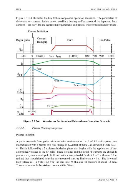
ITER G A0 FDR 1 01-07-13 R1.0Figure <strong>3.7</strong>.3-4 illustrates the key features of plasma operation scenarios. The parameters ofthe scenario – current, fusion power, auxiliary heating and/or current drive input and burnduration – can vary, but the sequencing requirements and general waveforms remain invariant.Figure <strong>3.7</strong>.3-4Waveforms for Standard Driven-burn Operation Scenario<strong>3.7</strong>.3.2.1 Plasma Discharge SequencePlasma InitiationA pulse proceeds from pulse initiation with attainment at t = 0 of PF coil system premagnetisationwith a plasma-axis flux linkage of φ SOP (start of pulse), as shown in Figure <strong>3.7</strong>.3-4. This is followed by a 2 s plasma initiation phase that begins with the application of predeterminedvoltages to the PF coils. These voltages and the initial PF currents are chosen toproduce a dynamic multipole field null with a low poloidal field (< 2 mT within an 0.8 mradius) that is positioned near the port-mounted start-up limiters at t ≈ 1 s. The in-vesselloop voltage is ~ 12 V (E ≈ 0.3 Vm -1 ) at this time. With a gas fill pressure of about 1.3 mPa,Townsend avalanche breakdown occurs within 50 ms.<strong>Plant</strong> Description Document Chapter 3 .7 Page 14