3.7 Plant Control - General Atomics Fusion Group
3.7 Plant Control - General Atomics Fusion Group
3.7 Plant Control - General Atomics Fusion Group

You also want an ePaper? Increase the reach of your titles
YUMPU automatically turns print PDFs into web optimized ePapers that Google loves.
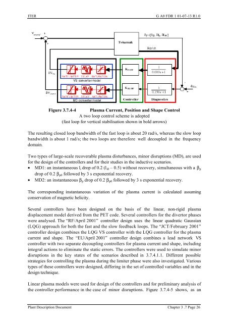
ITER G A0 FDR 1 01-07-13 R1.0Figure <strong>3.7</strong>.4-4 Plasma Current, Position and Shape <strong>Control</strong>A two loop control scheme is adopted(fast loop for vertical stabilisation shown in bold arrows)The resulting closed loop bandwidth of the fast loop is about 20 rad/s, whereas the slow loopbandwidth is about 1 rad/s; the two loops are therefore well decoupled in the frequencydomain.Two types of large-scale recoverable plasma disturbances, minor disruptions (MD), are usedfor the design of the controllers and for their studies in the inductive scenarios.• MD1: an instantaneous l i drop of 0.2 (l i0 – 0.5) without recovery, simultaneous with a β pdrop of 0.2 β p0 followed by 3 s exponential recovery.• MD2: an instantaneous β p drop of 0.2 β p0 followed by 3 s exponential recovery.The corresponding instantaneous variation of the plasma current is calculated assumingconservation of magnetic helicity.Several controllers have been designed on the basis of the linear, non-rigid plasmadisplacement model derived from the PET code. Several controllers for the divertor phaseswere analysed. The “RF/April 2001” controller design uses the linear quadratic Gaussian(LQG) approach for both the fast and the slow feedback loops. The “JCT/February 2001”controller design combines the LQG VS controller with the LQG controller for the plasmacurrent and shape. The “EU/April 2001” controller design combines a lead network VScontroller with two separate decoupling controllers for plasma current and shape, includingintegral actions to eliminate the static errors. The controllers were used to simulate minordisruptions in the key states of the scenarios described in <strong>3.7</strong>.4.1.1. Different possiblestrategies for controlling the plasma during the limiter phase were also investigated. Varioustypes of these controllers were designed, differing in the set of controlled variables and in thedesign technique.Linear plasma models were used for design of the controllers and for preliminary analysis ofthe controller performance in the case of minor disruptions. Figure <strong>3.7</strong>.4-5 shows, as an<strong>Plant</strong> Description Document Chapter 3 .7 Page 26