27C512 EPROM Data Sheet.pdf - Downloads.reactivemicro.com
27C512 EPROM Data Sheet.pdf - Downloads.reactivemicro.com
27C512 EPROM Data Sheet.pdf - Downloads.reactivemicro.com

You also want an ePaper? Increase the reach of your titles
YUMPU automatically turns print PDFs into web optimized ePapers that Google loves.
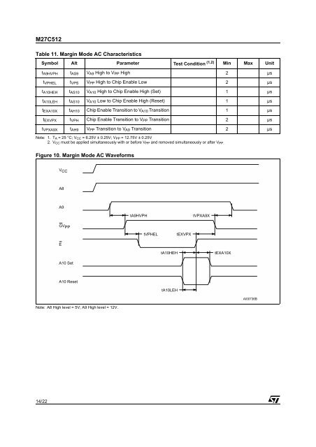
M<strong>27C512</strong>Table 11. Margin Mode AC CharacteristicsSymbol Alt Parameter Test Condition (1,2) Min Max Unitt A9HVPH t AS9 V A9 High to V PP High 2 µst VPHEL t VPS V PP High to Chip Enable Low 2 µst A10HEH t AS10 V A10 High to Chip Enable High (Set) 1 µst A10LEH t AS10 V A10 Low to Chip Enable High (Reset) 1 µst EXA10X t AH10 Chip Enable Transition to V A10 Transition 1 µst EXVPX t VPH Chip Enable Transition to V PP Transition 2 µst VPXA9X t AH9 V PP Transition to V A9 Transition 2 µsNote: 1. T A = 25 °C; V CC = 6.25V ± 0.25V; V PP = 12.75V ± 0.25V2. V CC must be applied simultaneously with or before V PP and removed simultaneously or after V PP.Figure 10. Margin Mode AC WaveformsV CCA8A9tA9HVPHtVPXA9XGV PPtVPHELtEXVPXEtA10HEHtEXA10XA10 SetA10 ResettA10LEHAI00736BNote: A8 High level = 5V; A9 High level = 12V.14/22