MRHB™ White Paper
MRHB™ White Paper
MRHB™ White Paper

You also want an ePaper? Increase the reach of your titles
YUMPU automatically turns print PDFs into web optimized ePapers that Google loves.
AWR ®MRHB <strong>White</strong> <strong>Paper</strong>THE ADVANTAGES OF MULTI-RATE HARMONIC BALANCE(MRHB) -- ADVANCED, MULTI-TONE HARMONIC BALANCETECHNOLOGY PIONEERED BY AWRHarmonic balance (HB) analysis is a method used to calculate the nonlinear,steady-state frequency response of electrical circuits. It is extremely well-suitedfor designs in which transient simulation methods prove acceptable, such asdispersive transmission lines in which circuit time constants are large comparedto the period of the simulation frequency, as well as for circuits that have a largenumber of reactive components. In particular, harmonic balance analysis worksextremely well for microwave circuits that are excited with sinusoidal signals, suchas mixers and power amplifiers.Harmonic balance analysis has been the fundamental simulation solution fornonlinear frequency-domain simulation for more than 25 years, and the mostadvanced versions are more capable than ever. AWR’s APLAC ® HB simulator,for example, can efficiently solve designs with thousands of analysis frequencies,and its ability to scale in a near-linear fashion as circuit elements, nodes, andfrequencies increase makes it highly productive.The limitation of traditional harmonic balance analysis occurs when it is used tosolve large circuits with many different signal sources because it requires longcomputational times and large amounts of computer memory. To make harmonicbalance analysis viable when analyzing such circuits, AWR has developed a multirateharmonic balance (MRHB) technology within its APLAC family of harmonicbalance and time-domain simulators. MRHB overcomes the aforementionedlimitations, significantly reducing the solution time as well as the computermemory required when applied to frequency-rich nonlinear systems that havemultiple signal sources. The capabilities provided with MRHB make it possible tosolve entire complex subsystems such as mobile phone transceivers in a practicalamount of time.This white paper traces the use of harmonic balance in solving microwaveproblems, describes MRHB technology, and provides examples of its effectivenesswhen compared with traditional harmonic balance simulators.HARMONIC BALANCE: A BRIEF HISTORYUntil the 1980s, SPICE and similar transient analysis techniques were thereigning champions for solving complex microwave circuits. However, as thedecade progressed, harmonic balance rapidly displaced SPICE among RF andmicrowave designers because transient analysis required far too much time toreach a steady-state solution and quickly used up available memory even whenpresented with simple topologies containing distributed elements. Its limitationsbecame glaringly obvious when solving mixers and other types of frequencyconversiondevices in which frequencies change over a wide spectrum. In theworld of analysis, these widely-separated frequencies are called tones.Circuit SimulationTechnology forHighly Nonlinear andComplex DesignsDr. Mike HeimlichAWR Corporationmike@awrcorp.comDr. Michael Heimlich, a well-known memberof the RF/microwave industry, joined AWRin 2001.Prior to AWR, he was the chief technologyofficer and founder of Smartlynx, an EDAinteroperability company.Earlier, Dr. Heimlich held several positionsat MA/COM including CAE Manager for theIC Business Unit and principal engineer in ICproduct development. He also designed GaAsMMICs for Pacific Monolithics and designedspace-qualified millimeter-wave mixers atWatkins Johnson. Dr. Heimlich earned hisBSEE, MSEE, and PhD EE degrees fromRenssalear Polytechnic.CO-AUTHORS:Taisto Tinttunen, director of engineering,AWR-APLAC CorporationVille Karanko, senior development engineer,AWR-APLAC Corporation
AWRMRHB<strong>White</strong> <strong>Paper</strong>A technique called “multi-tone harmonic balance analysis” was developed that made it possible toconsider analyzing receivers and transmitters. These early harmonic balance engines incorporateddirect matrix methods that were very useful in steady-state analysis of a circuit with a fewtransistors. However, when they were presented with larger nonlinear circuits, the resulting denseconversion matrices devoured computer memory and required many hours of simulation time.In the 1990s, harmonic balance technology got a much-needed boost when numerical analysistechniques appeared that were better-suited for solving large nonlinear problems. Direct matrixtechniques were supplemented with iterative techniques and the naïve Newton iteration wasreplaced by so-called inexact Newton methods. The use of more advanced and better optimizedfast Fourier transform (FFT) techniques produced great advances in how nonlinear devicecomputations were performed.A NEW OBSTACLEHarmonic balance has been a true enabler of steady-state nonlinear analysis with distributedelements, but as the number of tones (independent frequencies) increases, the number ofmathematical unknowns that must be solved grows geometrically. This occurs because in a multitonesystem, each circuit element must be solved not just at the harmonics of each tone, but alsoat many of their linear combinations as well. If the designer cannot constrain the harmonic balanceanalysis engine by limiting the number of frequency combinations per circuit element, the circuitmust be analyzed for the same frequencies at every circuit node. In a typical multi-tone circuit, forexample, this means that a lot of CPU time is consumed to refine a zero.The number of analysis frequencies becomes a bottleneckwhen the number of tones grows above three, a phenomenonappropriately labeled by the numerical analysis community asthe Curse of Dimension. Table 1 helps clarify the ramificationsof the “curse,” and demonstrates what happens even in amoderately nonlinear simulation when the number of tones isincreased. When fortified with the increased accuracy produced Table 1. The Curse of Dimension.by “diamond truncation” (the strategy of selecting frequencylinear combinations), the growth in the number of frequencies and hence the number of unknownsto be solved is almost an order of magnitude for every tone. This presents an untenable situationthat renders most current harmonic balance solutions ineffective as they are faced with processingextraordinary amounts of information in order to achieve a result.AN INNOVATIVE NEW APPROACH - MRHBTo understand the sea change enabled by MRHB, it is important to remember its core concept:that operational blocks such as mixers, filters, and amplifiers in an RF system modify thefrequency content. As traditional harmonic balance techniques assume that the relevant frequencycontent will be the same at every part (or block) in the circuit, it is essentially “out of sync” withhow the circuit actually functions. Rather than perpetuating this concept, MRHB enables thedesigner to allow different parts of the circuit to have different dominating frequencies, andtakes into consideration that some frequencies are important to solve while others are not. Thisintelligent, frequency-selective technique makes it possible to solve very complex circuits such asreceivers with multiple stages of downconversion, multi-band power amplifiers, and complex highfrequencydigital designs, an order of magnitude faster than with traditional harmonic balance.
AWRMRHB<strong>White</strong> <strong>Paper</strong>MRHB dynamically forms its equations to solve for the multi-tone, multiharmoniccontent of the circuit, adding the contribution of each element(block) only at the desired frequencies, which dramatically reduces thenumber of equations that must be solved. The analysis informationis transferred from one element (block) to another via the sharedfrequencies, as illustrated in the simple example in Figure 1 in which acircuit has been divided into two blocks, each with single-tone frequencyset. The first part (the red block) has eight harmonics and the secondone (the blue block) has four. Communication between these two circuitsoccurs via the five frequencies they share, DC, and four harmonics. Thefirst part is solved at all nine frequencies, which actually makes the resultsmore accurate because of the greater number of harmonics.While the solution of such simple circuits generally achieves little byreducing frequency content at some parts of the circuit, many circuitsrequire one of their nonlinear parts to be simulated more accurately.MRHB does not force this local accuracy requirement to affect thesimulation of other parts of the circuit, so if a frequency divider requiresmore than 2,000 harmonics for a single-tone analysis, it can be simulatedlocally with a large single-tone frequency set without detrimentally impactingthe two-tone frequency set used in the same simulation for the mixer.Figure 1. This simple, three-node circuit has two blockswith different frequency settings, both ofwhich are single tone. Block 1 (red) has eightharmonics and Block 2 (blue) has four.In short, MRHB presumes that by intelligently addressing the fact thatdominating frequencies differ in the various parts of a circuit, it is possibleto realize more efficient, yet highly accurate harmonic balance analysis ofthe entire circuit. This remarkable feat is accomplished while at the sametime consuming less memory and less simulation time than traditionalharmonic balance techniques.EXAMPLES TO ILLUSTRATE MRHBRefer again to the simple circuit in Figure 1, in which the first block has avoltage source and a nonlinear diode, and the corresponding circuit equationsare constructed for DC and eight harmonics. Assuming that the diode is beingdriven hard enough to generate significant harmonic content, an ordinaryharmonic balance simulation would require the analysis of all circuit elements—nonlinear as well as linear—to be analyzed at all eight harmonics. The secondpart of the circuit implements a low-pass filter that would be expected toblock the higher-order harmonics, introducing negligible signal energy at thesefrequencies to later elements in the circuit.Using MRHB as the simulation engine for analyzing this circuit’s behavior,the designer is able to individually set the analysis of the resistors anda capacitor to have a frequency set of only DC and four harmonics. Thesecond block in the circuit does not exist in frequencies 5f1, 6f1, 7f1,and 8f1 and the current I flows from block 1 to block 2 only for theshared frequencies, i.e., DC, f1, 2f1, 3f1, and 4f1. So only the relevantfrequencies and harmonics are solved on a block-by- block basis, makingit possible to deliver simulation accuracy more efficiently, which in turnenables MRHB to address circuits of greater complexity.
AWRMRHB<strong>White</strong> <strong>Paper</strong>Looking at the two relevant domains in which MRHB can be employed:• In the single-tone, multiple-frequency domain of Figure 1, MRHBselects only the required nonlinear elements rather than all nonlinearharmonics propagated to all circuit elements• In the multi-tone, multiple-frequency domain of Figure 2, MRHBreduces the overall tone-frequency solution space yet maintains highaccuracy through the use of hybrid-tonesTo illustrate the concept of hybrid tones, consider the QPSK receivershown in Figure 2, which is a challenging circuit to solve at the circuitlevel with harmonic balance analysis because of its multiple tones and theneed to employ many harmonics to tackle all the nonlinearities. The circuitconsists of a transistor-level QPSK receiver with 130 transistors basedon the BSIM3 model and more than 100 passive elements. Two-toneharmonic balance analysis would traditionally be used with a box-styletruncation up to the seventh order at the RF frequency (fRF = 2.45 GHz)and the fourth order at the LO frequency (fLO = 2.44 GHz). However, bypartitioning the blocks based on their frequency content, MRHB analysiscan employ a multi-tone frequency set, which eliminates many of theharmonics in the circuit elements where they are clearly not a factor.In the mixer within the circuit of Figure 2, the simulation results areachieved in half the time using half the memory with no difference inaccuracy between measured versus simulated results when comparedwith traditional harmonic balance. For the differential-to-single-ended andBessel filter blocks, the simulation consists of a single-tone, fourth-orderanalysis in which the fundamental frequency is constructed as an MRHBhybrid tone, fRF-fLO. By using this unique feature of MRHB in conjunctionwith the software’s ability to set multi-tonal frequency analysis on ablock-by-block basis, the resources necessary to analyze the receiver arereduced well beyond what is possible with traditional harmonic balanceusing either box or diamond truncation.Table 2 summarizes the memory consumption and processor times oftraditional harmonic balance versus MRHB simulation for this design.Voltage magnitude is plotted in Figure 3 from different parts of the circuitat selected frequencies (LO and RF), their second harmonics, and theirthird-order intermodulation products. Simulated data agrees very well withthe actual circuit behavior and yet was achieved in nearly one-fourth thesimulation time while using half the memory.Figure 2. A QPSK receiver with 130 transistors and morethan 100 passive components. The elements withsingle-tone frequency settings are shown in blackand the rest of the elements belong to a block witha two-tone frequency set.Table 2. Performance comparison between traditionalharmonic balance and MRHB for Figure 2 QPSKreceiver.Figure 3. The mixer sub circuit of Figure 2 outputspectrum from traditional harmonic balance (Δ)and MRHB (□).
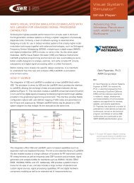
AWRMRHB<strong>White</strong> <strong>Paper</strong>EXAMPLE: MRHB SUCCEEDS WHERE HB FAILSMore than just speeding up traditional HB, with MRHB it is possibleto simulate circuits that are impossible for harmonic balance to tackledue to the memory limitations of its formulation. A key feature of theMRHB technique is that the HB solution space can be defined on ablock-by-block basis and, as such, limits the harmonics over which thesimulator must solve. In other words, MRHB redefines the tones soas to advantageously direct the simulator to solve for only those tonesthat matter.Compare, for example, a design that both HB and MRHB are ableto tackle. Figure 4 shows a simple behavioral simulation for a GPSdouble-downconverter. The two mixing stages combined with the RFinput yields three tones which, with default HB set-up parameters,requires less than 1000 harmonics for the HB simulator to solveover. Even though HB can handle this design, MRHB can be used toselectively prune this solution space by solving only at the necessarytones seen by each component. Because of this unique feature,the initial low noise amplifier (LNA) in the receive chain need only beanalyzed at the input with the harmonics of the RF input signal—aone-tone solution. Similarly, those components seeing only the firstmixing products are constrained by MRHB block 2 (see Figure 5) andthe analysis is done only for the RF and first LO—a two-tone MRHBsolution. Finally, with the second downconversion and the subsequentstages, components of all three tones are required. For thecomponents in this part of the design, and only for these components,MRHB utilizes all three tones. While MRHB solves significantly fasterfor this design than traditional HB, it is also important to note that theresults are virtually identical (Figure 6)But MRHB provides an additional feature for this third MRHB blockthat makes its use even more intuitive. Rather than simply defining thethree tones for the final MRHB block as the RF, first LO, and secondLO, “solve” tones can be constructed from these three “simulation”tones that are of greater interest. In this case, for the LO leakage,which can compress this part of the design, two of the solve tones tobe the LO tones are specified to the MRHB engine. For the third tone,tracking the GPS IF is most interesting and so the proper harmonicof RF, LO1 and LO2 is specified. The advantage of this specification isthat MRHB can simulate using the precise number of harmonics ofinterest for the precise signals of interest (rather than the simulationtones). So, the user can control MRHB to focus on the IF even thoughthere is no tonal source in the solution that directly corresponds tothe IF. This capability of MRHB gives the designer the ability to havethe solver track the tones of interest in each separate part of thedesign, corresponding to the MRHB blocks.Figure 4. GPS double-downconverter for HB solution.Figure 5. GPS double-downconverter for MRHB solution.MRHB blocks 1 and 2 show associated elements,the remaining elements are subject to MRHB block3. Note that tone 3 of MRHB block 3 is createdfrom the 3 simulation tones.Figure 6. Time-domain results for MRHB and HB for GPSdouble-downconverter.
AWRMRHB<strong>White</strong> <strong>Paper</strong>Pushing this notion further, a simple common-gate field-effect transistor(FET) (Figure 7) is added to the design to act as a sampling circuit, forexample, to have the receiver feed a data acquisition system or analogto-digitalconverter (ADC). With the default HB behavior, something onthe order of 10,000 harmonics is required of the solution, which wouldcause most desktop PCs to fail to solve due to a lack of memory. Thecorresponding MRHB solution to this circuit not only solves, but doesit in one-third the time that it takes the simple double-downconverter inFigure 5. (This is using what might be considered a default or nonaggressiveMRHB simulation set-up)In order to make HB work on this design, the number of harmonicsconsidered must be drastically pared. For example, even reducing thenumber of harmonics from about 10,000 to 1,000 the solve timeis still more than four times that of the default MRHB simulation.Although the HB simulation is solving at more harmonics than MRHB,MRHB is actually treating more of the harmonics that matter andaccounting for more of the energy through explicit tonal and harmonicselection. Thus, MRHB accuracy is superior, as can be seen inthe mismatch effects in Figure 8. While traditional HB still gives areasonable answer, it can be seen that the accuracy degrades purelyto get a solution on a standard PC.Figure 7. GPS double-downconverter with sampling FET forHB solution (MRHB solution is the same exceptwith 4 MRHB control blocks similar to Figure 5).Standard HB default settings cause this simulationto run out of memory on a standard PC.To see this example demonstrated in AWR’s Microwave Office ®software, view the video on AWR.TV titled “Multi-Rate HarmonicBalance Tutorial.”CONCLUSIONTraditional harmonic balance analysis continues to be a core componentin the designer’s toolbox, but is limited in its ability to solve the large,high-frequency circuits with many signal sources that are becomingmore and more prevalent in today’s complex designs. The intelligentfrequency selectivity and other innovative features within AWR’s patentpendingMRHB technology transcend the shortcomings of traditionalharmonic balance and enable designers to solve these complex circuitsin significantly shorter time and with more accuracy.Figure 8. Results for sampling circuit + GPS doubledownconverter,comparing high accuracyMRHB, fast MRHB, and HB made to runon a standard PC.AWR, 1960 East Grand Avenue, Suite 430, El Segundo, CA 90245, USATel: +1 (310) 726-3000 Fax: +1 (310) 726-3005 www.awrcorp.comCopyright © 2010 AWR Corporation. All rights reserved. AWR, the AWR logo, APLAC and Microwave Officeare registered trademarks and MRHB and AWR.TV are trademarks of AWR Corporation.