Hot Water Design Manual Rev D - Rinnai
Hot Water Design Manual Rev D - Rinnai
Hot Water Design Manual Rev D - Rinnai

You also want an ePaper? Increase the reach of your titles
YUMPU automatically turns print PDFs into web optimized ePapers that Google loves.
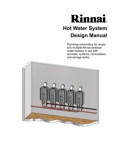
<strong>Hot</strong> <strong>Water</strong> System<strong>Design</strong> <strong>Manual</strong>Plumbing schematics for singleand multiple <strong>Rinnai</strong> tanklesswater heaters in use withdomestic systems, recirculation,and storage tanks.
Table of ContentsCertifications ................................................................ 3, 4<strong>Rinnai</strong> Accessories ......................................................... 4MSB Kits for Connecting Multiple <strong>Water</strong> Heaters ........ 5Model Applicability .......................................................... 6<strong>Water</strong> Quality and Scale ................................................. 7Pump Sizing for Circulation ........................................... 8Tank <strong>Water</strong> Heaters in a Circulation Loop .................... 9Additional Guidelines ..................................................... 9Vent Termination Clearances ....................................... 10Additional Clearances ................................................... 12Pump Sizing for Storage Tank Applications .............. 14Pressure Loss Curves - Non Condensing Models ..... 15Pressure Loss Curves - Condensing Models ............. 16Condensing <strong>Water</strong> HeatersDrawing No. DescriptionCWH1 1 Basic Piping ................................... 17CWH2 2 Basic Piping ................................... 18CWH3 3 Basic Piping ................................... 19CWH6 6 Basic Piping ................................... 20CWH1-C 1 Circulation System ........................ 21CWH2-C 2 Circulation System ........................ 22CWH3-C 3 Circulation System ........................ 23CWH6-C 6 Circulation System ........................ 24CWH1-BC 1 Backup Storage ............................. 25CWH2-BC 2 Backup Storage ............................. 26CWH3-BC 3 Backup Storage ............................. 27CWH6-BC 6 Backup Storage ............................. 28Non-condensing <strong>Water</strong> HeatersDrawing No. DescriptionWH1 1 Basic Piping ................................... 29WH2 2 Basic Piping ................................... 30WH3 3 Basic Piping ................................... 31WH6 6 Basic Piping ................................... 32WH1-D 1 Freeze Protection .......................... 33WH2-D 2 Freeze Protection .......................... 34WH3-D 3 Freeze Protection .......................... 35WH6-D 6 Freeze Protection .......................... 36WH1-RGE 1 Optional Recirculation ................... 37WH1-R 1 Optional Recirculation ................... 38WH1-CD-O 1 Preferred Demand Circulation ....... 39WH1-CD 1 Preferred Demand Circulation ....... 40WH2-CP 2 Circulation System ........................ 41WH3-CP 3 Circulation System ........................ 42WH6-CP 6 Circulation System ........................ 43WH1-BC 1 Backup Storage ............................. 44WH2-BC 2 Backup Storage ............................. 45WH3-BC 3 Backup Storage ............................. 46WH6-BC 6 Backup Storage ............................. 47WH1-AHU 1 Hydronic Furnace .......................... 48WH1-AHU-RES 1 Hydronic Furnace andHeat Exchanger............................. 49WH1-A1-CD 1 Demand Circulation with 1 <strong>Rinnai</strong>Hydronic Furnace .......................... 50WH2-A1-CD 1 Combination System with 2 <strong>Rinnai</strong>Hydronic Furnaces ........................ 51WH1-AH 1 Generic Air Handler ....................... 52WH1-S-1 1 Solar Backup ................................. 53Maintenance ProcedureWH1-F 1 Flush Procedure ............................ 54Legend ......................................................................... 552 R-TRWH-E-02 <strong>Rev</strong> D
Indoor <strong>Water</strong> HeatersCertificationsTrade Name CSA Listing Trade Name CSA ListingV53i, RV53i ........... REU-VB2020FFU-US-(N, P)R50LSi .................. REU-VA2019FFUD-US-(N, P) *R75LSi, RL75i ...... REU-VB2528FFUD-US-(N, P) * R75LSi .................. REU-VA2528FFUD(A)-UC-(N, P) *R75LSi .................. REU-VA2528FFUD(A)-US-(N, P) *R75LSi .................. REU-VA2528FFUD-US-(N, P) *R94LSi, RL94i ...... REU-VB2735FFUD-US-(N, P) * R94LSi .................. REU-VA2535FFUD-UC-(N, P)*R94LSi .................. REU-VA2535FFUD-US-(N, P)*R98LSi .................. REU-VA3237FFU-US-(N, P) *R98LSiASME ........ REU-VA3237FFU-ASME-(N, P) *R53i ...................... REU-V2520FFU-US-(N, P)C53i ...................... REU-V2520FFUC-US-(N, P) *R53i ...................... REU-V2520FFUD-US-(N, P)C53i ...................... REU-V2520FFUCD-US-(N, P) *R85i ...................... REU-V2532FFU-US-(N, P)C85i ...................... REU-V2532FFUC-US-(N, P) *R85iPLUS ............. REU-V2532FFUD-US-(N, P)C85iPLUS ............. REU-V2532FFUCD-US-(N, P) *R98i ...................... REU-V3237FFU-US-(N, P)C98i ...................... REU-V3237FFUC-US-(N, P) *R98iASME ............ REU-V3237FFU-ASME-(N, P)C98iASME ............ REU-V3237FFUC-ASME-(N, P) *RC80HPi, RC80i .. REU-KA2530FFUD-US-(N, P)*RC98HPi, RC98i .. REU-KA3237FFUD-US-(N, P)** authorized for commercial use Energy Star QualifiedThe models listed above have received the following certifications except where noted:Certified to applicable U.S.standards for appliances usinggas or other petroleum fuel.Certified to applicable Canadianstandards for appliances usinggas or other petroleum fuel.Certified by the UniformPlumbing Code (UPC)Certified by National SanitationFoundation (NSF), www.nsf.org(indoor models must use theNSF approved top guard)REU-VAM1620W is not NSFapprovedOutdoor <strong>Water</strong> HeatersV53e, RV53e ...........REU-VAM1620W-US-(N, P)R63LSe ...................REU-VA2024WD-US-(N, P) *R63LSe2 .................REU-VA2024WD(A)-UC-(N, P) *R75LSe, RL75e ......REU-VB2528WD-US-(N, P) * R75LSe ...................REU-VA2528WD(A)-UC-(N, P) *R75LSe ...................REU-VA2528WD(A)-US-(N, P) *R75LSe ...................REU-VA2528WD-US-(N, P) *R94LSe, RL94e ......REU-VB2735WD-US-(N, P) * R94LSe ...................REU-VA2535WD-UC-(N, P) *R94LSe ...................REU-VA2535WD-US-(N, P) *R98LSe ...................REU-VA3237W-US-(N, P) *R98LSeASME .........REU-VA3237W-ASME-(N, P) *R42e .......................REU-V1616W-US-(N, P)C42e .......................REU-V1616WC-US-(N, P) *R53e .......................REU-V2020W-US-(N, P)C53e .......................REU-V2020WC-US-(N, P) *R70e .......................REU-V2526W-US-(N, P)R85e .......................REU-V2532W-US-(N, P)C85e .......................REU-V2532WC-US-(N, P) *R85ePLUS ..............REU-V2532WD-US-(N, P)C85ePLUS ..............REU-V2532WCD-US-(N, P) *R98e .......................REU-V3237W-US-(N, P)C98e .......................REU-V3237WC-US-(N, P) *R98eASME .............REU-V3237W-ASME-(N, P)C98eASME .............REU-V3237WC-ASME-(N, P) *RC80HPe, RC80e ...REU-KA2530WD-US-(N, P)*RC98HPe, RC98e ...REU-KA3237WD-US-(N, P)*Energy efficiency certified byGas Appliance ManufacturersAssociation (GAMA),www.ahrinet.orgMeets the California EnergyCommission (CEC) standardsMeets California and Texas NOXemission rulesApproved by the Commonwealthof MassachusettsApproved for installations in NewYork CityEnergy Star Qualified (modelsindicated with )3 R-TRWH-E-02 <strong>Rev</strong> D
CertificationsRR98LSiASMER98LSeASMER98iASMEC98iASMER98eASMEC98eASMEMultiple Unit Connections (refer to model applicability)These models are built in accordance with the requirements of the ASME Boiler andPressure Vessel Code and received the Certificate of Authorization from the NationalBoard. The heat exchanger has the NB and the HLW stamps.<strong>Rinnai</strong> AccessoriesMSB Controller: The MSB kits can electronically connect up to 25 water heaters and allows them to function asone hot water source. For use with <strong>Rinnai</strong> Tankless <strong>Water</strong> Heaters (except for models V53e,V53i, and R63LSe which must use pressure activation valves, PVA). Refer to the information inthe next section for components.EZConnect :PVA Valves:The EZConnect cable is an optional accessory that electronically connects 2 water heatersand allows them to function as one hot water source.Pressure activated valves that allow each water heater (max 5) to turn on as necessary to meetthe demand for hot water. A PVA valve is also useful when dedicating one <strong>Rinnai</strong> in a multiple<strong>Rinnai</strong> system for hot water circulation. The PVA valve will allow flow from the cold water supplyto the dedicated unit when a differential pressure is exerted on the PVA valve due to domesticdemand.Guidelines formultiple unitconnections:• Do not install both the EZConnect and the MSA/MSB packs because they are not designed tooperate together.• <strong>Water</strong> heaters connected with the EZConnect Cable or the MSA/MSB packs cannot be usedfor the bathfill function.• Temperature settings can only be changed on the controller for the primary unit.• Do not use the EZConnect or MSA/MSB packs with storage tank applications.<strong>Rinnai</strong> Installation Kits - Valve kits provide isolation valves (for hot and cold lines) and a pressure relief valve. ModelsRV53e, RV53i, RL75i/e, RL94i/e, RC80i/e, and RC98i/e include isolation valves and apressure relief valve.WRIK-LF-F Valve kit (for models rated below 200,000 Btuh), Lead Free, 3/4” - E2 version,FNPT X FNPT, (threaded)WRIK-LF-32F Valve kit (for models rated above 200,000 Btuh), Lead Free, 3/4” - E2 version,FNPT X FNPT, (threaded)104000059 Freeze Protection Solenoid Valve KitRemote Controllers: MC-91-1US - Controller included with the unit except for the V53e and V53i.MCC-91-1US - For commercial and hydronic applications allowing temperatures above 140º F.MC-100V-1US - Deluxe controllerBC-100V-1US - Bathroom controllerRecess Boxes:Pipe Covers:Recesses unit into the wall, protecting and hiding the unit from viewFor security, weather protection, and finished look<strong>Rinnai</strong> is continually updating and introducing new products and accessories. For the latest information, contact<strong>Rinnai</strong> at 1-800-621-9419, FAX: 1-888-474-6624, or www.rinnai.us.4 R-TRWH-E-02 <strong>Rev</strong> D
MSB Kits for Connecting Multiple <strong>Water</strong> Heaters<strong>Water</strong> HeaterPC boardAEach bank is controlled by an MSB-M control board. These boards areconnected to each other with MSB-C2 cables. One MSB-M is thecontrolling or master MSB-M for the entire system.C1C2MMAMSB-M control boardConnector cable A (part of MSB-M kit; replace with MSB-C3cables for V Series)C1 MSB-C1 cable for connecting water heaters within a bankedsystem (up to 5), (use MSB-C3 cables for V Series)C2 MSB-C2 cable for connecting MSB-M control boards (up to 5)No. ofwaterheatersNo. of waterheaters foreach bankNumber of Kits RequiredMSB-M MSB-C1Seenote *MSB-C2 MSB-C3Seenote *2** 2 1 NA NA 13 3 1 1 NA 24 4 1 2 NA 35 5 1 3 NA 46 3/3 2 2 1 47 4/3 2 3 1 58 4/4 2 4 1 69 5/4 2 5 1 710 5/5 2 6 1 811 4/4/3 3 5 2 812 4/4/4 3 6 2 913 5/4/4 3 7 2 1014 5/5/4 3 8 2 1115 5/5/5 3 9 2 1216 4/4/4/4 4 8 3 1217 5/4/4/4 4 9 3 1318 5/5/4/4 4 10 3 1419 5/5/5/4 4 11 3 1520 5/5/5/5 4 12 3 1621 5/4/4/4/4 5 11 4 1622 5/5/4/4/4 5 12 4 1723 5/5/5/4/4 5 13 4 1824 5/5/5/5/4 5 14 4 1925 5/5/5/5/5 5 15 4 20MSB Kits - Parts NeededUse the table to determine the type andnumber of kits necessary for your system.Up to 5 water heaters can be connectedtogether using the MSB-M and MSB-C1 kits.When over 5 water heaters are connectedtogether, MSB-M control boards areconnected using MSB-C2 kits.If multiple MSB-M control boards are used,then at least three water heaters should beconnected to each MSB-M. Example: With 7water heaters, one MSB-M should control 4water heaters and the other MSB-M shouldcontrol 3 water heaters.Detailed installation instructions are providedwith each of the kits.* VA, VB, and KA (Condensing) models usethe MSB-M, MSB-C1, and MSB-C2 cablesV Series models use the MSB-M, MSB-C2,and MSB-C3 cables. V Series modelsmust use the MSB-C3 cables instead ofthe MSB-C1 cables and the Cable A in theMSB-M.** The <strong>Rinnai</strong> EZConnect is less expensiveand is specifically designed for connecting2 water heaters. Applicable models areVA, VB, KA, and V3237.5 R-TRWH-E-02 <strong>Rev</strong> D
Model Applicability (Accessories)OutdoorModel Recess Boxes Pipe CoversElectronicConnectionRemoteControllersV53e, RV53ePC-20-W (white) [6] [1]RGB-20-UR63LSe2 PCD01-SM2 (silver) [2]R75LSe, RL75e,R94LSe, RL94eR98LSe, R98LSeASMERC80HPe, RC80e,RC98HPe, RC98eRGB-25-UorRGB-25U-MSAL(with moistureseal flange)RGB-32PCD03-SM2 (silver) [2]EZConnect [5],MSA-2, MSBPC-32-W (white)PC-32-G (gray)RGB-CTWH PCD07 [2][2]IndoorModelVenting TypeIntegratedCondensateCollectorElectronicConnectionRemoteControllersV53i, RV53iR50LSiR75LSi, RL75i,R94LSi, RL94iConcentric 3” / 5”[4] YESEZConnectR98LSi, R98LSiASME4” for intake and4” for exhaustNO [3][5],MSA-2, MSB [2][4]RC80HPi, RC80i,RC98HPi, RC98iConcentric 3” / 5”[4][2]YES [2]Notes[1] MC-91, MC-100, BC-100[2] MC-91, MC-100, BC-100, MCC-91[3] The Condensate Collector vent piece and the Condensate Trap (224050) for trapping and draining condensate maybe required depending on your installation. Refer to the Operation and Installation <strong>Manual</strong>.[4] Refer to the Operation and Installation <strong>Manual</strong>[5] The EZConnect will connect a maximum of 2 water heaters.[6] Electronic connection is not available for this model. Connection can be made using pressure activating <strong>Rinnai</strong> PVAvalves.6 R-TRWH-E-02 <strong>Rev</strong> D
<strong>Water</strong> Quality and ScaleA complete water analysis and an understandingof system requirements are needed to protect the<strong>Rinnai</strong> tankless water heaters and water heatingsystems from scale. <strong>Water</strong> analysis showswhether water is hard or soft. Hard water, unlesstreated, will cause scaling or liming of the <strong>Rinnai</strong>heat exchanger.The rate of scaling increases with temperatureand usage because calcium carbonate and otherscaling compounds lose solubility (fall out ofsolution) at higher temperatures. For example,for every 20°F over 140°F, the rate of scaleincreases by a factor of 2 (See figure below).Reference target water quality levels below andtreat the water if these levels are exceeded.LIME DEPOSITED, lb/yr210180150120906030BASED ON 10 grains/gal HARDNESS *180°F170°F160°F150°F140°F003009001500210027003300120°F3900WATER USAGE, gal/day* Source 2003 ASHRAE Handbook HVAC ApplicationsConsideration of care for your water heater shouldinclude evaluation of water quality.<strong>Water</strong> that contains chemicals exceeding thelevels shown in the table affect and damage theheat exchanger. Replacement of the heatexchanger due to water quality damage is notcovered by the warranty.If you live in an area that is known to have hard wateror that causes scale build-up you must treat yourwater and/or flush the heat exchanger regularly.When scale build-up in the heat exchanger begins toaffect the performance of the water heater, adiagnostic code “LC” will display. Flush the heatexchanger to prevent damage to it. Scale build up iscaused by hard water set at a high temperature.Total HardnessAluminum *Chlorides *Copper *Iron *Manganese *Maximum LevelUp to 200 mg / LUp to 0.2 mg / LUp to 250 mg / LUp to 1.0 mg / LUp to 0.3 mg / LUp to 0.05 mg / LpH * 6.5 to 8.5TDS (Total DissolvedSolids) *Up to 500 mg / LZinc *Up to 5 mg / L* Source: Part 143 National Secondary Drinking <strong>Water</strong>Regulations7 R-TRWH-E-02 <strong>Rev</strong> D
Pump Sizing for Circulation1. Use the chart below or one appropriate for your conditions to determine the heat loss in the length of the hot watersupply and return piping. For example, 100 ft of 1-1/2 in bare copper tubing results in a heat loss of 5300 Btu/h.Approximate Heat Loss from Piping at 140 ºF Inlet, 70 ºF Ambient *Nominal Size, in.Bare Copper Tubing,Btu/h-ft1/2 in. Glass Fiber InsulatedCopper Tubing, Btu/h-ft3/4 30 17.71 38 20.31-1/4 45 23.41-1/2 53 25.42 66 29.62-1/2 80 33.83 94 39.54 120 48.4* Source: 2011 ASHRAE Handbook HVAC Applications2. Determine the acceptable temperature drop at the last fixture in the loop. For example, if the supply temperature fromthe water heater is 120 ºF (49 ºC) and an acceptable temperature at the last fixture is 100 ºF (38 ºC) then theacceptable temperature drop is 20 ºF (7 ºC).3. Calculate the required pump flow rate using the following formula:FLOW RATE (gpm) = HEAT LOSS (BTU / h)500 X ACCEPTABLE TEMPERATURE DROP (ºF )4. Based on the above calculations select a pump for the type of circulation system you will be utilizing:A). Optional Method (reference drawing WH1-RGE) - Reference pump manufacturers flow vs. pressurespecifications to select a pump that can provide the flow rate calculated above while overcoming thepressure loss through:• Tank water heater (reference manufacturer’s information)• All building supply and return plumbing in the circulation loop (reference local plumbing codes,standards, or practices)B). Preferred Method (WH1-CD-O, WH1-CD) - Reference pump manufacturers flow vs. pressure specificationsto select a pump that can provide 3 gpm of flow or the flow rate calculated above, whichever is greater, whileovercoming the pressure loss through:• <strong>Rinnai</strong> tankless water heater (reference flow vs. pressure curve of the <strong>Rinnai</strong> model being used)• Optional storage tank (reference manufacturer’s information)• All building supply and return plumbing in the circulation loop (reference local plumbing codes,standards, or practices)NOTE: Only use pumps of brass, bronze, or stainless steel construction. Do not use pumps of iron construction asthey will oxidize and clog the inlet filter on the appliance. The pump should be controlled by an aquastat,timer, or combination of the two. A demand control (motion sensor, push button, or door contact) may alsobe used.8 R-TRWH-E-02 <strong>Rev</strong> D
Tank <strong>Water</strong> Heaters in a Circulation LoopThe following applies when using a tank water heater (gas or electric) to provide heat for a circulation loop. DrawingWH1-RGE is an example.The heat output of the tank must be equal to or greater than the calculated circulation loop heat loss.(Reference page 7, Step 1 on calculating heat loss).Electric Tank <strong>Water</strong> HeaterSince the input and output are the same for an electric tank water heater, this can be expressed as:Electric Tank Input (Kw) > Circulation loop heat loss (Btuh)3413(1 Kilowatt = 3,413 BTU)Gas Tank <strong>Water</strong> HeaterWhen using a gas style water heater, the efficiency of the tank must be taken into account.Example:Available Btuh output = (Btu input of tank) x (efficiency) > Circulation loop heat loss (Btuh)30,000 Btuh input gas tank0.62 EF30,000 x .62 = 18,600 available Btuh outputAdditional Guidelines<strong>Rinnai</strong> water heaters not recovering a storage tank: In applications involving a commercial dishwasher, a hot watercirculation loop feeding the dishwasher is required.<strong>Rinnai</strong> water heater recovering a storage tank: In applications involving a commercial dishwasher, a hot watercirculation loop feeding the dishwasher may be required depending on the distance between the dishwasher and thestorage tank. Refer to local codes when determining the need for circulation loops to dishwashers.When using a <strong>Rinnai</strong> product as the heat source for a circulation loop, the piping systems should be designed with a hotwater circulation loop having a minimum circulating flow rate of 3 gpm. You must also review pressure drop curves forthe <strong>Rinnai</strong> when sizing circulators.<strong>Rinnai</strong> water heaters cannot be used in applications requiring 180º-195º F water at a DISHWASHER, unless a boosterheater capable of producing 180º-195º F water is provided at the dishwasher. The <strong>Rinnai</strong> water heater is not to be usedas a booster water heater in these applications.For beauty salon applications, a hot water circulation loop feeding the head wash stations is highly recommended. Thisprovides instant hot water to the head wash stations and reduces the possibility of cold bursts at the stations. (Refer tothe piping schematics in this manual.) Insulation of circulation piping is also recommended for heat retention.Exhaust gases from beauty salon applications and fume hoods of commercial dish washers with chemical sanitizers canbe highly corrosive and may cause premature failure of water heater components. Care must be taken to ensure thatthe water heater and vent termination are installed away from that area. An uncontaminated supply of combustible airmust be maintained for optimum performance of the water heater.If the intended installation is located in hard water area, a softener or similar water treatment system must be used.Always remember to perform routine maintenance.For any applications requiring temperatures above 140º F, an MCC-91 temperature controller must be purchasedseparately.9 R-TRWH-E-02 <strong>Rev</strong> D
Vent Termination ClearancesTERMINATIONClearance inRef. A alsoapplies toanticipatedsnow lineSNOWINSIDECORNER DETAILGHADEBBFIXEDCLOSEDOPERABLEIMKBCFIXEDCLOSEDBBAJLOPERABLEFBXAIR SUPPLY INLETVVENT TERMINALAREA WHERETERMINAL IS NOTPERMITTTED10 R-TRWH-E-02 <strong>Rev</strong> D
Vent Termination ClearancesRef Description Canadian Installations US InstallationsAClearance above grade, veranda, porch,deck, or balcony12 inches (30 cm) 12 inches (30 cm)BClearance to window or door that may beopened36 inches (91 cm) 12 inches (30 cm)C Clearance to permanently closed window * *DVertical clearance to ventilated soffit,located above the terminal within ahorizontal distance of 2 feet (61 cm) fromthe center line of the terminal* *E Clearance to unventilated soffit * *F Clearance to outside corner * *G Clearance to inside corner * *HClearance to each side of center lineextended above meter/regulator assembly3 feet (91 cm) within aheight 15 feet (4.5 m)above the meter/regulator assemblyI Clearance to service regulator vent outlet 36 inches (91 cm) *JClearance to nonmechanical air supplyinlet to building or the combustion air inletto any other applianceK Clearance to a mechanical air supply inlet 6 feet (1.83 m)LClearance above paved sidewalk orpaved driveway located on public property36 inches (91 cm) 12 inches (30 cm)*3 feet (91 cm) above ifwithin 10 feet (3 m)horizontally7 feet (2.13 m) 1 *MClearance under veranda, porch, deck, orbalcony12 inches (30 cm) 2 *NOTE: An outdoor water heater with integral vent and intake is functionally similar to a direct ventproduct in that the combustion air is drawn from the outside and the flue products are vented to theoutside. These clearances apply to indoor and outdoor water heaters.1 A vent shall not terminate directly above a sidewalk or paved driveway that is located between twosingle family dwellings and serves both dwellings.2 Permitted only if veranda, porch, deck, or balcony is fully open on a minimum of two sides beneaththe floor.∗ For clearances not specified in ANSI Z223.1/NFPA 54 or CSA B149.1, clearances are inaccordance with local installation codes and the requirements of the gas supplier.11 R-TRWH-E-02 <strong>Rev</strong> D
Additional ClearancesThese clearances are to supplement the clearances specified in ANSI Z223.1 which are currently in theFFU (indoor) and W (outdoor) manuals. They apply to all water heater models. Local codes supersedethese recommendations.General Recommendations• Avoid termination locations near a dryer vent. (See TB-46 for more information.)• Avoid termination locations near commercial cooking exhaust.W (Outdoor) Models(0.30 m) to aninside corner12"36"(0.91 m) to ventilated or unventilated soffit or eve vent; or to adeck or porch2"(50 mm) between <strong>Rinnai</strong> units at same level60"(1.52 m) vertically between <strong>Rinnai</strong> terminals12 R-TRWH-E-02 <strong>Rev</strong> D
Termination of FFU (Indoor) ModelsAdditional Clearances60" (1.52 m) verticallybetween <strong>Rinnai</strong> terminals12"(0.30 m ) to aninside corner36"12"(0.91 m) to ventilatedor unventilated soffitor eve vent; or to adeck or porch(0.30 m) between<strong>Rinnai</strong> terminals atsame level24"(0.61 m) to wall or parapetINSIDECORNER(1.52 m) between<strong>Rinnai</strong> terminalsat different levels60"12"(0.30 m) between<strong>Rinnai</strong> terminals atsame level13 R-TRWH-E-02 <strong>Rev</strong> D
Pump Sizing for Storage Tank ApplicationThe following applies when using <strong>Rinnai</strong> tankless water heaters to recover a storage tank. Drawing WH1-BC is anexample.<strong>Rinnai</strong> Tankless water heaters have a pressure loss which must be considered in the system design. Reference thepressure loss curve for the <strong>Rinnai</strong> model being used to determine the pump size for the desired recovery rate.For recommended pump sizes use the table below. Additional pressure losses in plumbing between the <strong>Rinnai</strong>(s) andthe storage tank must also be taken into consideration.The specified pump size is to provide maximum recovery of the storage tank. A smaller pump size may be used, butcould result in longer recovery time of the tank. Please contact the engineering department with any questions on pumpsizing.NOTE: Only use pumps of brass, bronze, or stainless steel construction. Do not use pumps of iron construction asthey will oxidize and clog the inlet filter on the appliance.Pump Flow RequirementsNumber of <strong>Rinnai</strong><strong>Water</strong> HeatersR94LSi/e, RL94i/eR98LSi/e(ASME)RC80HPi/e, RC80i/eRC98HPi/e, RC98i/eR/C53i(PLUS)R70eR75LSi/e, RL75i/eV53e, RV53eV53i, RV53iR50LSiR63LSe21 6 gpm @ 30' head 5 gpm @ 25' head 4 gpm @ 25' head2 12 gpm @ 30' head 10 gpm @ 25' head 8 gpm @ 25' head3 18 gpm @ 30' head 15 gpm @ 25' head 12 gpm @ 25' head4 24 gpm @ 30' head 20 gpm @ 25' head 16 gpm @ 25' head5 30 gpm @ 30' head 25 gpm @ 25' head 20 gpm @ 25' head6 36 gpm @ 30' head 30 gpm @ 25' head 24 gpm @ 25' head7 42 gpm @ 30' head 35 gpm @ 25' head 28 gpm @ 25' head8 48 gpm @ 30' head 40 gpm @ 25' head 32 gpm @ 25' head9 54 gpm @ 30' head 45 gpm @ 25' head 36 gpm @ 25' head10 60 gpm @ 30' head 50 gpm @ 25' head 40 gpm @ 25' head11 66 gpm @ 30' head 55 gpm @ 25' head 44 gpm @ 25' head12 72 gpm @ 30' head 60 gpm @ 25' head 48 gpm @ 25' head13 78 gpm @ 30' head 65 gpm @ 25' head 52 gpm @ 25' head14 84 gpm @ 30' head 70 gpm @ 25' head 56 gpm @ 25' head15 90 gpm @ 30' head 75 gpm @ 25' head 60 gpm @ 25' head14 R-TRWH-E-02 <strong>Rev</strong> D
Pressure Loss Curves - Non Condensing Models45R50LSiR63LSeR75LSi/eRL75i/eR94LSi/eRL94i/eR98LSi/eR98LSi/eASME1004090Pressure Loss (psi)35302520151080706050403020Pressure Loss (ft head)51000 1 2 3 4 5 6 7 8 9 10 11<strong>Water</strong> Flow (gpm)04510040903580Pressure Loss (psi)30252015105V53eRV53eV53iRV53i70605040302010Pressure Loss (ft head)000 1 2 3 4 5 6<strong>Water</strong> Flow (gpm)15 R-TRWH-E-02 <strong>Rev</strong> D
Pressure Loss Curves - Condensing ModelsPressure Loss (psi) )RC80HPi/eRC80i/eRC98HPi/eRC98i/ePressure Loss (ft head)<strong>Water</strong> Flow (gpm)16 R-TRWH-E-02 <strong>Rev</strong> D
17 R-TRWH-E-02 <strong>Rev</strong> D
18 R-TRWH-E-02 <strong>Rev</strong> D
19 R-TRWH-E-02 <strong>Rev</strong> D
20 R-TRWH-E-02 <strong>Rev</strong> D
21 R-TRWH-E-02 <strong>Rev</strong> D
22 R-TRWH-E-02 <strong>Rev</strong> D
23 R-TRWH-E-02 <strong>Rev</strong> D
24 R-TRWH-E-02 <strong>Rev</strong> D
25 R-TRWH-E-02 <strong>Rev</strong> D
26 R-TRWH-E-02 <strong>Rev</strong> D
27 R-TRWH-E-02 <strong>Rev</strong> D
28 R-TRWH-E-02 <strong>Rev</strong> D
29 R-TRWH-E-02 <strong>Rev</strong> D
30 R-TRWH-E-02 <strong>Rev</strong> D
31 R-TRWH-E-02 <strong>Rev</strong> D
32 R-TRWH-E-02 <strong>Rev</strong> D
33 R-TRWH-E-02 <strong>Rev</strong> D
34 R-TRWH-E-02 <strong>Rev</strong> D
35 R-TRWH-E-02 <strong>Rev</strong> D
36 R-TRWH-E-02 <strong>Rev</strong> D
37 R-TRWH-E-02 <strong>Rev</strong> D
38 R-TRWH-E-02 <strong>Rev</strong> D
39 R-TRWH-E-02 <strong>Rev</strong> D
40 R-TRWH-E-02 <strong>Rev</strong> D
41 R-TRWH-E-02 <strong>Rev</strong> D
42 R-TRWH-E-02 <strong>Rev</strong> D
43 R-TRWH-E-02 <strong>Rev</strong> D
44 R-TRWH-E-02 <strong>Rev</strong> D
45 R-TRWH-E-02 <strong>Rev</strong> D
46 R-TRWH-E-02 <strong>Rev</strong> D
47 R-TRWH-E-02 <strong>Rev</strong> D
48 R-TRWH-E-02 <strong>Rev</strong> D
49 R-TRWH-E-02 <strong>Rev</strong> D
50 R-TRWH-E-02 <strong>Rev</strong> D
51 R-TRWH-E-02 <strong>Rev</strong> D
52 R-TRWH-E-02 <strong>Rev</strong> D
Solar BackupSolar Backup53 R-TRWH-E-02 <strong>Rev</strong> D
Flush ProcedureSingle Unit Flush Procedure1. Disconnect electrical power to the water heater.2. Close the shutoff valves on both the hot waterand cold water lines (V3 and V4).3. Connect pump outlet hose (H1) to the cold waterline at service valve (V2).4. Connect drain hose (H3) to service valve (V1).5. Pour 4 gallons of undiluted virgin, food grade,white vinegar into pail.6. Place the drain hose (H3) and the hose (H2) tothe pump inlet into the cleaning solution.7. Open both service valves (V1 and V2) on the hotwater and cold water lines.8. Operate the pump and allow the cleaning solutionto circulate through the water heater for at least 1hour at a rate of 4 gallons per minute (15.1 litersper minute).9. Turn off the pump.10. Rinse the cleaning solution from the water heateras follows:a. Remove the free end of the drain hose (H3)from the pail. Place in sink or outside to drain.b. Close service valve, (V2), and open shutoffvalve, (V4). Do not open shutoff valve, (V3).c. Allow water to flow through the water heaterfor 5 minutes.d. Close shutoff valve (V4). When unit hasfinished draining remove the in-line filter at thecold water inlet and clean out any residue.Place filter back into unit and open valve (V4).e. Close service valve, (V1), and open shutoffvalve, (V3).11. Disconnect all hoses.13. Restore electrical power to the water heater.54 R-TRWH-E-02 <strong>Rev</strong> D
55 R-TRWH-E-02 <strong>Rev</strong> D
© 2011 <strong>Rinnai</strong> America CorporationR-TRWH-E-02 <strong>Rev</strong> D8/2011