Tankless Rack System - Rinnai
Tankless Rack System - Rinnai
Tankless Rack System - Rinnai

Create successful ePaper yourself
Turn your PDF publications into a flip-book with our unique Google optimized e-Paper software.
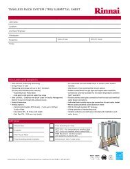
SpecificaonsDescription(2) RU98Wall Mount(3) RU98Wall Mount(4) RU98Wall MountTop Level Part No. RW2 RW3 RW4<strong>Rack</strong> Frame - Specifications RW2 RW3 RW4Water Heater ModelRU98i/e N/PFrame (HxLxD) - in54.81 x 41.50 x12.7554.81 x 62.00 x12.7554.81 x 82.50 x12.75Crate Dimensions (HxLxD) - in 62 x 55 x 36 62 x 75 x 36 62 x 95 x 36Weight - Assembly w/o WHs - lbs 44.1 63.4 82.6Weight - Water Heaters - lbs 131.4 197.1 262.8Weight - Fully Assembled - lbs 175.5 260.5 345.4Weight - Packaging - lbs 121.0 142.0 148.0Weight - Shipping (total) - lbs 296.5 402.5 493.4Description(4/4) RU98Free Stand (b)(3/4) RU98Free Stand (b)(2/4) RU98Free Stand (b)Top Level Part No. RS4-4 RS4-3 RS4-2<strong>Rack</strong> Frame - SpecificationsWater Heater ModelRF4RU98i/e N/PFrame (HxLxD) - in 55.56 x 41.50 x 28.5Crate Dimensions (HxLxD) - in 62 x 55 x 36Weight - Assembly w/o WHs - lbs 96.1 88.1 80.1Weight - Water Heaters - lbs 262.8 197.1 131.4Weight - Fully Assembled - lbs 358.9 285.2 211.5Weight - Packaging - lbs 129.0 129.0 129.0Weight - Shipping (total) - lbs 487.9 414.2 340.5Description(6/6) RU98Free Stand (b)(5/6) RU98Free Stand (b)(3/6) RU98Free Stand (b)Top Level Part No. RS6-6 RS6-5 RS6-3<strong>Rack</strong> Frame - SpecificationsWater Heater ModelRF6RU98i/e N/PFrame (HxLxD) - in 55.56 x 62.00 x 28.5Crate Dimensions (HxLxD) - in 62 x 75 x 36Weight - Assembly w/o WHs - lbs 124.6 116.6 100.6Weight - Water Heaters - lbs 394.2 328.5 197.1Weight - Fully Assembled - lbs 518.8 445.1 350.2Weight - Packaging - lbs 148.0 148.0 148.0Weight - Shipping (total) - lbs 666.8 593.1 498.25 <strong>Rinnai</strong> <strong>Rack</strong> Installation
SpecificaonsDescription(2, 3, 4) RU98Wall Mount(4/4, 3/4, 2/4)RU98Free Stand (b)(6/6, 5/6, 3/6)RU98Free Stand (b)Top Level Part No.RW2, RW3,RW4RS4-4, RS4-3,RS4-2RS6-6, RS6-5,RS6-3<strong>Rack</strong> Frame - Specifications RW2, RW3, RW4 RF4 RF6Frame Rail Type Sheet Metal Sheet Metal Sheet MetalFrame Material 0.090 5052-H32 0.090 5052-H32 0.090 5052-H32Frame Finish Powder Coat Powder Coat Powder CoatColor Gray Gray GrayWater & Gas ConnectionsHot Water Trunk Line Diameter 2" 2" 2-1/2"Cold Water Trunk Line Diameter 2" 2" 2-1/2"Hot Water Trunk Line Material Rigid Copper Rigid Copper Rigid CopperCold Water Trunk Line Material Rigid Copper Rigid Copper Rigid CopperWater Trunk Connection Type 2" MNPT 2" MNPT 2-1/2" MNPTWater Header End Cap (field supplied) 2” FNPT 2” FNPT 2-1/2” FNPTHot Water Branch Line Diameter 3/4" 3/4" 3/4"Cold Water Branch Line Diameter 3/4" 3/4" 3/4"Hot Water Branch Line Material CSST CSST CSSTCold Water Branch Line Material CSST CSST CSSTGas Trunk Line Diameter 1-1/4" NPT 1-1/4" NPT 1-1/2" NPTGas Trunk Connection Type 1-1/4” MNPT 1-1/4” MNPT 1-1/2” MNPTGas Header End Cap (field supplied) 1-1/4” FNPT 1-1/4” FNPT 1-1/2” FNPTGas Trunk Line Material Sch 40 Steel Sch 40 Steel Sch 40 SteelGas Branch Line Diameter 3/4" 3/4" 3/4"Gas Branch Line MaterialPVC Over CSST PVC Over CSST PVC Over CSSTGas Trunk Line Finish Powder Coat Powder Coat Powder CoatUniStrut Size 1-5/8" x 13/16" 1-5/8" x 1-5/8" 1-5/8" x 1-3/8"UniStrut Material 14ga Steel / Zn 12ga S/S 12ga S/SHardware Material/Finish Steel / Zn S/S 18-8 S/S 18-8Electrical RequirementsEach water heater requires 120 VAC, 60 Hz powersource in a properly grounded circuit.RU98i: 64 W normal operation; 2 W standby; 146 Wanti-frost protection.RU98e: 63 W normal operation; 2 W standby; 168 Wanti-frost protection.BTU and Flow Rates for Common Vented RU98i/e (NG/LP)2 RU98 3 RU98 4 RU98 5 RU98 6 RU98Flow rate @ 70°F rise (gpm) 10.8 16.2 21.6 27.0 32.4Flow rate @ 100°F rise (gpm) 7.6 11.4 15.2 19.0 22.8Maximum input rate (Btuh) 398,000 597,000 796,000 995,000 1,194,0006 <strong>Rinnai</strong> <strong>Rack</strong> Installation
ClearancesInstall the rack system so that the clearances shown below (specified for the water heater in the RU98i andRU98e installation manual) are followed.to topto topto frontto frontto sideto sideto floor/groundIndoor models: RU98ito floor/groundOutdoor models: RU98etoCombustiblesto Non-CombustiblestoCombustiblesto Non-Combustiblesinches (mm)inches (mm)inches (mm)inches (mm)Top of Heater 6 * (152) 2 *(51)Back of Heater 0 (zero) 0 (zero)Front of Heater 6 (152) 6 (152)Sides of Heater 2 (51) 1/2 (13)Ground/Bottom 12 (305) 12 (305)Vent 0 (zero) 0 (zero)Top of Heater 12 (305) 2 (51)Back of Heater 0 (zero) 0 (zero)Front (panel) 24 (610) 0 (zero)Front (exhaust) 24 (610) 24 (610)Sides of Heater 6 (152) 1/8 (3.2)Ground/Bottom 12 (305) 2 (51)* 0 inches from vent components and condensatedrain line.The clearance for servicing is 24 inches in front of thewater heater.For closet installation, clearance is 6 inches (152 mmfrom the front.The clearance for servicing is 24 inches in front of thewater heater.7 <strong>Rinnai</strong> <strong>Rack</strong> Installation
Mounng Wall <strong>Rack</strong>s1. Idenfy the installaon locaon and confirm that the installaon will meet all required clearances.2. Securely aach the rack to the wall. Ensure that the aachment strength is sufficient to support the weight.Refer to the weight in the Specificaons secon.Use a leveling tool to ensure that the water heater is level. Proper operaon requires that the water heaterbe level. The rack / water heaters should be installed in an upright posion. Do not install upside down oron its side.Securing Free Standing <strong>Rack</strong>s1. Use 4‐1/2” HILTI KB‐TZ expansion anchors or approved equivalent. Minimum embedment (hef) = 3.25”.Minimum concrete thickness to be 6”.2. All mechanical components shall be anchored and installed per the notes in this manual. Where no detail isindicated, anchorage of equipment to building structure shall be in accordance to the applicable naonaland/or local codes having jurisdicon.3. The size and embedment specified are for anchors installed in stone or aggregate concrete only, for otheranchorage details the contractor or engineer on record for the building shall consult with a licensed structuralengineer for all anchorage of equipment not called out in this manual.4. In the event of a conflict or inconsistency between items indicated in this manual with code requirements,the more stringent standard shall prevail.28.5026.5028.5026.5036.5334.51Boom view offree standingracks.55.1153.090.563(4) Plcs0.563(4) Plcs9 <strong>Rinnai</strong> <strong>Rack</strong> Installation
Relief Valve PipingEach <strong>Rinnai</strong> tankless water heater on the TRS comes installed with Isolaon valves and a pressure relief valve.Refer to the installaon and operaon manual for more informaon on proper piping for the relief valve drain.Pressure Relief ValveIsolaon ValvePiping for Mulple <strong>Rack</strong>sMulple rack systems should be installed in parallel using a secondary manifold from the building cold and hotwater supply. Reference the drawing for guidance.A low pressure gas regulator must be installed prior to the rack system. Note the maximum cumulave input forthe system when sizing the gas regulator.Use common plumbing pracce and reference all applicable codes when sizing the secondary manifolds and gasregulator.10 <strong>Rinnai</strong> <strong>Rack</strong> Installation
11 <strong>Rinnai</strong> <strong>Rack</strong> Installation
Condensate DrainEach <strong>Rinnai</strong> tankless water heater has a condensatedrain outlet on the boom of the unit. A drain linemust be connected to each water heater.Condensate Drain Manifold must be field fabricated(not shown in diagram)Condensate piping shall be CPVC or PVC material andshall not be smaller than the drain connecon on theappliance.Components of the condensate drainage shall beCPVC or PVC material. All components shall beselected for the pressure and temperature rang ofthe installaon.Where the drain pipes from more than one unit aremanifolded together for condensate drainage, thepipe or tubing shall be sized in accordance with anapproved method as dictated by local codes.Condensate must be disposed of according to localcodes.Piping Diagram for Basic InstallaonWaterdrain plugGasconnectionCold waterinletChecklist for Plumbing□ Purge the water line of all debris and air byclosing the hot isolaon valve and opening thecold isolaon valve and its drain. Debris willdamage the water heater. Use a bucket or hoseif necessary.□ Ensure that hot and cold water lines are notcrossed to the unit and are leak free.□ Ensure that a pressure relief valve is installed witha rang that exceeds the BTU input of the waterheater model. Refer to the rang plate on theside of the water heater for BTU input.□ Clean the inlet water filter by closing the cold andhot water inlet isolaon (shut‐off) valves. Put abucket under the filter at the boom of the waterheater to catch any water that is contained insidethe unit. Unscrew the water filter. Rinse thefilter to remove any debris. Install the filter andopen the isolaon valves.□ Check for proper water pressure to the waterheater. Minimum water pressure is 50 psi. <strong>Rinnai</strong>recommends 60‐80 psi for maximumperformance.Hot wateroutletCondensatetrap drain plugCondensatedrain lineThe condensate drain pipe (along its entirelength) must be at least the same diameteras the drain line.13 <strong>Rinnai</strong> <strong>Rack</strong> Installation
Installaon of Gas SupplyWARNING1. If you are not knowledgeable or qualified toinstall gas lines or connecons, then contact alicensed professional to install the gas supply.2. Turn off 120v power supply.3. Turn off the gas.4. Gas is flammable. Do not smoke or provide otherignion sources while working with gas.5. Do not turn on the water heater or gas unl allfumes are gone.MUST DO• Check the type of gas and the gas inlet pressurebefore connecng the water heater. If the waterheater is not of the gas type that the building issupplied with, DO NOT connect the water heater.Contact the dealer for the proper unit to match thegas type.• Check the gas supply pressure immediately upstreamat a locaon provided by the gas company.Supplied gas pressure must be within the limitsshown in the Specificaons secon with all gas appliancesoperang.• Before placing the appliance in operaon all jointsincluding the heater must be checked for gas ghtnessby means of leak detector soluon, soap andwater, or an equivalent nonflammable soluon, asapplicable. (Since some leak test soluons, includingsoap and water, may cause corrosion or stresscracking, the piping shall be rinsed with water aertesng, unless it has been determined that the leaktest soluon is non‐corrosive.)• Use approved connectors to connect the unit tothe gas line. Purge the gas line of any debris beforeconnecon to the water heater.• Any compound used on the threaded joint of thegas piping shall be a type which resists the acon ofliquefied petroleum gas (propane / LPG).Connecng ElectricityWARNINGDo not use an extension cord or an adapter plug withthis appliance.The water heater must be electrically grounded inaccordance with local codes and ordinances or, in theabsence of local codes, in accordance with theNaonal Electrical Code, ANSI/NFPA No. 70.Indoor water heaters are equipped with a threeprong(grounding) plug for your protecon againstshock hazard and should be plugged directly into aproperly grounded three‐prong receptacle. Do notcut or remove the grounding terminal from this plug.Do not rely on the gas or water piping to ground thewater heater. A screw is provided in the juncon boxfor the grounding connecon.The water heater requires 120 VAC, 60 Hz power froma properly grounded circuit.If using the 5 foot long power cord, plug it into astandard 3 prong 120 VAC, 60 Hz properly groundedwall outlet.On outdoor models, a disconnect switch must beprovided and installed for the incoming 120 VACpower. It should be a type that is suitable for outdooruse. Check the Naonal Electrical Code, ANSI/NFPA70 and your local codes for a proper switch type touse in your area.The wiring diagram is located on the Technical Sheetaached to the inside of the front cover.120V WiringBlue or Black wire: hot legBrown or White Wire: neutral• The gas supply line shall be gas ght, sized, and soinstalled as to provide a supply of gas sufficient tomeet the maximum demand of the heater and allother gas consuming appliances at the locaonwithout loss of pressure.14 <strong>Rinnai</strong> <strong>Rack</strong> Installation
MSB InstallaonAll of the water heaters should be electronically connectedusing the MSB control system. The only excep‐on is when a water heater is dedicated to recovering atank. The MSB kits can electronically connect up to 25water heaters.When over 5 water heaters are connected together,MSB‐M units are connected using MSB‐C2 kits.If mulple MSB‐M are used, then at least three waterheaters should be connected to each MSB‐M. Example:With 7 water heaters, one MSB‐M should control 4 waterheaters and the other MSB‐M should control 3 waterheaters.Water HeaterPC boardC1AC2MThe temperature seng for all of the connected waterheaters is controlled by the temperature controllerconnected to the water heater with the master MSBBoard. Temperature controllers connected to the otherunits will provide maintenance codes for their respec‐ve units.On applicable models a single MCC‐91 can be connectedto the master MSB Board to provide temperaturesgreater than 140ºF for all the water heaters in the MSBsystem.In the diagram above, 25 water heaters areelectronically connected. Each bank of 5 is controlledby an MSB‐M control board. These boards areconnected to each other with MSB‐C2 cables. OneMSB‐M is the controlling or master MSB‐M for theenre system.MAMSB-M control boardConnector cable A (part of MSB-M kit; replacewith MSB-C3 cables for V Series)C1 MSB-C1 cable (9.8 feet) for connecting waterheaters within a banked system (up to 5), (useMSB-C3 cables for V Series)C2 MSB-C2 cable (13.1 feet) for connecting MSB-Mcontrol boards (up to 5)15 <strong>Rinnai</strong> <strong>Rack</strong> Installation
MSB Installaon1. On the master MSB, one connector is connected tothe terminal connector and the other one is connectedto the MSB Communicaon cable.Master MSB board2. When 2 MSB boards are used a MSB Communica‐on cable will be installed between the masterMSB board and the second MSB. The open connectorwill have the Terminal connector installedon both MSB boards.A maximum of 5 MSB boards can be connected to eachother. The terminal connector is connected on the terminalMSB which has an open connector.NOTE: When viewing the installed MSB board, the dipswitch will be as shown below (upside down).2nd MSB board2nd to 4thMSB board5th or TerminalMSB board3. Set No 3 switch on the master MSB to ON. The LED light 6should turn ON confirming the connecon.4. Set No 4 switch on the second MSB to ON. The LED light 6should turn ON confirming the connecon.5. Set No 3 and No 4 switches on the third MSB board to ON. TheLED light 6 should turn ON confirming the connecon.6. Set the No 5 switch on the fourth MSB board to ON. The LEDlight 6 should turn ON confirming the connecon.7. Set No 3 and No 5 switches on the on the fih MSB board toON. The LED light 6 should turn ON confirming the connecon.16 <strong>Rinnai</strong> <strong>Rack</strong> Installation
Final Checklist□ The water heater is not subject to corrosivecompounds in the air.□ The water supply does not contain chemicals orexceeds total hardness that will damage the heatexchanger.□ Clearances from the water heater unit are met.□ Clearances from the vent termination / air intakeare met.□ For indoor models, ensure you have used thecorrect venting products for the model installedand that you have completely followed the ventingmanufacturer’s installation instructions and theseinstallation instructions.□ For indoor models, verify that the vent systemdoes not exceed the maximum length for thenumber of elbows used.□ For indoor models, verify that switch No. 1 in theSW1 DIP switch (tan switches) has been adjustedfor vent length if necessary. Refer to the sectionon Maximum Vent Length.□ Purge the water line of all debris and air by closingthe hot isolation valve and opening the coldisolation valve and its drain. Debris will damagethe water heater. Use a bucket or hose ifnecessary.□ Ensure that hot and cold water lines are notcrossed to the unit and are leak free.□ A manual gas control valve has been placed in thegas line to the water heater.□ Ensure that a pressure relief valve is installed witha rating that exceeds the BTU input of the waterheater model. Refer to the rating plate on the sideof the water heater for BTU input.□ Clean the inlet water filter by closing the cold andhot water inlet isolation (shut-off) valves. Put abucket under the filter at the bottom of the waterheater to catch any water that is contained insidethe unit. Unscrew the water filter. Rinse the filterto remove any debris. Install the filter and openthe isolation valves.□ Check the gas lines and connections for leaks.□ Confirm that the gas inlet pressure is within limits.□ Confirm that the water heater is rated for the gastype supplied.□ Confirm that the electricity is supplied from a 120VAC, 60 Hz power source, is in a properlygrounded circuit, and turned on.□ Verify the temperature controller is functioningproperly.□ Verify that switches No. 2 and No. 3 in the SW1DIP switch (tan switches) is set correctly for youraltitude.□ Verify the system is functioning correctly byconnecting your manometer to the gas pressuretest port on the water heater. Operate all gasappliances in the home or facility at high fire. Theinlet gas pressure at the water heater must notdrop below that listed on the rating plate.□ If the water heater is not needed for immediateuse, then drain the water from the heat exchanger.□ Install the front panel.□ Explain to the customer the importance of notblocking the vent termination or air intake.□ Explain to the customer the operation of the waterheater, safety guidelines, maintenance, andwarranty.□ The installation must conform with local codes or,in the absence of local codes, with the NationalFuel Gas Code, ANSI Z223.1/NFPA 54, or theNatural Gas and Propane Installation Code, CSAB149.1.□ Inform the consumer if a water softening system isnot installed.□ Leave the entire manual taped to the waterheater (indoor models), temperature controller(outdoor models), or give the entire manualdirectly to the consumer.17 <strong>Rinnai</strong> <strong>Rack</strong> Installation
Extended Limited LABOR Warranty*REGISTRATION REQUIRED*<strong>Tankless</strong> <strong>Rack</strong> <strong>System</strong><strong>Rinnai</strong> is providing the opportunity to extend your <strong>Rinnai</strong> Standard Limited Warranty for labor only on the tankless waterheater product installed as part of the <strong>Tankless</strong> <strong>Rack</strong> <strong>System</strong> and used in a commercial applicaon. You must register theproduct within 30 days of purchase of the system to qualify.The limited warranty period on the Labor coverage for <strong>Tankless</strong> Water Heaters installed on the <strong>Tankless</strong> <strong>Rack</strong> <strong>System</strong> is extendedfor an addional 12 months (a total of 24 months labor coverage from date of purchase), when registered. Productsnot registered will sll be covered under the <strong>Rinnai</strong> standard product limited warranty as provided in the Operang Instruconmanual which comes with the <strong>Tankless</strong> water heater. Warranty informaon is also available on <strong>Rinnai</strong>'s website at www.rinnai.us. You can register at www.rinnairegistraon.com or by calling 1‐866‐RINNAI‐1 (746‐6241), exceptregistraon is not required in California and Quebec.What is covered?This Limited Warranty covers any defects in materials or workmanship when the product is installed and operated accordingto <strong>Rinnai</strong> wrien installaon instrucons, subject to the terms within this Limited Warranty document. This Limited Warrantyapplies only to products that are installed correctly. Improper installaon may void this Limited Warranty. <strong>Rinnai</strong>strongly suggests that you use a licensed professional who has aended a <strong>Rinnai</strong> installaon training class before installingthis water heater. This Limited Warranty extends to the original purchaser and subsequent owners, but only while theproduct remains at the site of the original installaon. This Limited Warranty only extends through the first installaon ofthe product and terminates if the product is moved or reinstalled at a new locaon.How long does coverage last?ItemPeriod of Coverage (from date of purchase)Labor Parts Heat Exchanger<strong>Tankless</strong> Water Heaters 1 year (2) 5 years (1) 5 years (1)<strong>Rack</strong> and Components1 yearOnly applicable if product is registered within 30 days of purchase and the other condions are met. Note to Californiaand Quebec Residents, and residents of other jurisdicons that prohibit warranty benefits condioned on registraon,registraon is not required to obtain longer warranty periods and failure to register does not diminish your warrantyrights. www.rinnai.us/warranty[1] The warranty period is reduced to 3 years from date of purchase when the water heater is used as a circulang water heater within a hot watercirculaon loop, where the water heater is in series with a circulaon system and all circulang water flows through the water heater, and where anon‐demand recirculaon system is not incorporated.On‐demand recirculaon is defined as a hot water recirculang loop or system that ulizes exisng hot and cold lines or a dedicated return line, andonly acvates when hot water is used. It can be acvated by a push buon, moon sensor, or voice acvaon but not by a temperature sensor. Amer added to a standard recirculang pump is not considered as on‐demand.[2] Labor coverage is extended to 5 years in residenal applicaons and to 2 years in commercial applicaons if the product is registered within 30 days(except registraon is not required in California and Quebec) and/or if the other condions above in the Residenal Applicaons and CommercialApplicaons secons are sasfied.What will <strong>Rinnai</strong> do?<strong>Rinnai</strong> will repair or replace the covered product or any part or component that is defecve in materials or workmanship asset forth. <strong>Rinnai</strong> will pay reasonable labor charges associated with the repair or replacement of any part or component ofthe tankless water heater. All repair parts must be genuine <strong>Rinnai</strong> parts. All repairs or replacements must be performed bya licensed professional that is properly trained, state qualified or licensed to do the type of repair.Replacement of the product may be authorized by <strong>Rinnai</strong> only. <strong>Rinnai</strong> does not authorize any person or company to assumefor it any obligaon or liability in connecon with the replacement of the product. If <strong>Rinnai</strong> determines that repair of aproduct is not possible, <strong>Rinnai</strong> will replace the product with a comparable product at <strong>Rinnai</strong>’s discreon. If a component orproduct returned to <strong>Rinnai</strong> is found to be free of defects in material or workmanship, or damaged by improper installaon18 <strong>Rinnai</strong> <strong>Rack</strong> Installation
or damaged during return shipping, the warranty claim for product, parts and labor may be denied.How do I get service?You must contact a licensed professional for the repair of a product under this Limited Warranty. For the name of a licensedprofessional please contact your place of purchase, visit the <strong>Rinnai</strong> website (www.rinnai.us), call <strong>Rinnai</strong> at 1‐800‐621‐9419 or write to <strong>Rinnai</strong> at 103 Internaonal Drive, Peachtree City, Georgia 30269.Proof of purchase is required to obtain warranty service. You may show proof of purchase with a dated sales receipt, or byregistering within 30 days of purchasing the product. To register your tankless water heater, please visit www.rinnai.us.For those without internet access, please call 1‐866‐RINNAI1 (746‐6241). Receipt of Registraon by <strong>Rinnai</strong> will constuteproof‐of‐purchase for this product. However, Registraon is not necessary in order to validate this Limited Warranty.What is not covered?This Limited Warranty does not cover any failures or operang difficules due to the following:• accident, abuse, or misuse• alteraon of the product or any component part• misapplicaon of this product• improper installaon◊ Product being installed in a corrosive environment◊ condensate damage◊ improper venng◊ incorrect gas type◊ incorrect gas or water pressure◊ absence of a drain pan under the appliance• water quality• improper maintenance (such as but not limited to scale build‐up, freeze damage, or vent blockage)• incorrect sizing• any other cause not due to defects in materials or workmanship• Problems or damage due to fires, flooding, electrical surges, freezing or any acts of God.• force majeureThere is no warranty coverage on product installed in a closed loop applicaon, commonly associated with space heangonly applicaons.The integrated controller on indoor models has a 1 year warranty on parts.This Limited Warranty does not apply to any product whose serial number or manufacture date has been defaced. ThisLimited Warranty does not cover any product used in an applicaon that uses chemically treated water such as a pool orspa heater. This appliance is suitable for filling large or whirlpool bath tubs with potable water.Limitaon on warranesNo one is authorized to make any other warranes on behalf of <strong>Rinnai</strong> America Corporaon. Except as expressly providedherein, there are no other warranes, expressed or implied, including, but not limited to warranes of merchantability orfitness for a parcular purpose, which extend beyond the descripon of the warranty herein and further <strong>Rinnai</strong> shall not beliable for indirect, incidental, special, consequenal or other similar damages that may arise, including lost profits, damageto person or property, loss of use, inconvenience, or liability arising from improper installaon, service or use. Some statesdo not allow the exclusion or limitaon of incidental or consequenal damages, so the above limitaon may not apply toyou.Any implied warranes of merchantability and fitness arising under state law are limited in duraon to the period of coverageprovided by this Limited Warranty, unless the period provided by state law is less. Some states do not allow limitaonson how long an implied Limited Warranty lasts, so the above limitaon may not apply to you.This Limited Warranty gives you specific legal rights, and you may also have other rights which vary from state to state.19 <strong>Rinnai</strong> <strong>Rack</strong> Installation
10000029420 <strong>Rinnai</strong> <strong>Rack</strong> Installation 8/2012