Installation Instructions - Nordyne
Installation Instructions - Nordyne
Installation Instructions - Nordyne

You also want an ePaper? Increase the reach of your titles
YUMPU automatically turns print PDFs into web optimized ePapers that Google loves.
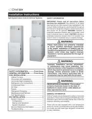
Split System Indoor Coils<strong>Installation</strong> <strong>Instructions</strong>CAUTION:Read the <strong>Installation</strong> <strong>Instructions</strong>supplied with furnace/air handler andobserve all safety requirements outlinedin instructions and/or furnace/airhandler markings before proceedingwith installation of the coilThese instructions are primarily intended toassist qualified individuals experienced in theproper installation of this appliance. Some localand national codes require licensed installation/servicepersonnel for this type of equipment.Read all instructions carefully before startingthe installation.
Table of Contents1. General Information ............................................................................................................... 32. Coil Specifications ................................................................................................................. 43. Coil <strong>Installation</strong> ....................................................................................................................... 5• Upflow Furnace• Downfl ow Furnace• Horizontal Furnace• Horizontal Ready Coils for Horizontal Left <strong>Installation</strong>• Horizontal Ready Coils for Horizontal Right <strong>Installation</strong>4. Refrigerant Line Connections ............................................................................................... 65. Completing the <strong>Installation</strong> ................................................................................................... 7• Condensate Drain• Air Filters• Close-off Plates and Panels• Refrigerant Charging6. Maintenance and Service ...................................................................................................... 82
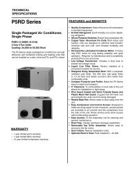
1. GENERAL INFORMATIONStandard cased coils are designed for upflow/downflow applications or horizontal applicationswhen used in conjunction with our horizontaldrain pan kit (See page 5). Accessory kits arenot required for factory ready horizontal coils.Coils are equipped with braze type refrigerantconnections for easy installation.Read the installation manual supplied with theoutdoor unit for refrigerant line connection procedure,required line sizes, and other informationpertaining to the system installation.1. Make certain that the air delivery of thefurnace/air handler is adequate to handlethe static pressure drop of the coil, fi lter, andduct work.2. Check the orifi ce size of the coil’s expansiondevice and confi rm that it is suitable for applicationwith the intended outdoor unit.NOTE: Some coils employ a thermostaticexpansion valve (TXV) as the meteringdevice (See page 4).3. Where precise forming of the refrigerantlines is required, a copper tubing benderdesigned for the size lines used is recommended.Avoid sharp bends and contact ofthe refrigerant lines with metal surfaces.4. Refrigerant lines should be wrapped withpressure sensitive neoprene or other suitablematerial where they pass through theraw edges of holes.5. Coil must be level for proper condensatedrainage.NOTE: Optional cooling/heating equipment mustbe properly sized and installed in accordancewith the furnace manufacturer’s specificationsand approved recommendations. “Heating only”furnace air circulators may have to be replacedwith multi-speed “Heating/Cooling” blowers toupgrade the air delivery (CFM) when an add-oncoil is installed. Refer to Coil Specifications forrecommended CFM and allow for pressure dropacross the coil and filters.19 3 /4"A 3/4"H13 3 /8"15 5 /8 "B16 5 /8"20 3 /4"WFigure 1.3
2. COIL SPECIFICATIONSCoil Model (1)C5BA/H024C-AC5BA/H025C-AC5BA/H030C-AC5BA/H024C-BC5BA/H025C-BNominal Capacity BTUH (2) 24,000 24,000 30,000 24,000 24,000 30,000 36,000 36,000 42,000 48,000 48,000 48,000 60,000Nominal Airflow CFM 800 800 1000 800 800 1000 1200 1200 1400 1600 1600 1600 2000Width (in.) W 14 1/4 14 1/4 14 1/4 19 3/4 19 3/4 19 3/4 19 3/4 19 3/4 19 3/4 19 3/4 22 1/2 22 1/2 22 1/2Height (in.) H (std/horz) 20/26 20/26 20/26 20/26 20/26 20/26 20/26 26/26 26/26 26/26 26/26 29/29 29/29Top (in.) A 12 7/8 12 7/8 12 7/8 18 3/8 18 3/8 18 3/8 18 3/8 18 3/8 18 3/8 18 3/8 21 1/8 21 1/8 21 1/8Connections Liquid Li Line 3/8 3/8 3/8 3/8 3/8 3/8 3/8 3/8 3/8 3/8 3/8 3/8 3/8Suction Line 3/4 3/4 3/4 3/4 3/4 3/4 3/4 7/8 7/8 7/8 7/8 7/8 7/8Installed Orifice Size (in.) (3) 0.050 0.060 0.065 0.050 0.060 0.065 0.075 0.075 0.078 0.089 0.089 0.089 0.099Horizontal Drain Kit (7) 919318 919318 919318 919318 919318 919318 919318 919319 919319 919319 919319 919320 919320Coil Case Adapter (4) - - - 913963 913963 913963 913963 913963 913963 913963 913964 913964 913964Extra Orifice (in.) N/A0.053 for1.5-toncondenser N/A N/AC5BA/H030C-BC5BA/H036C-BC5BA/H037C-BC5BA/H042C-BC5BA/H048C-BC5BA/H048C-CC5BA/H049C-CC5BA/H060C-C0.053 for1.5-toncondenser N/A N/A N/A N/A N/A N/A N/A N/ACoil Model (1)C5BA/HT/X24C-AC5BA/HT25C-AC5BA/HT/X30C-AC5BA/HT/X24C-BC5BA/HT25C-BNominal Capacity BTUH (2) 24,000 24,000 30,000 24,000 24,000 30,000 36,000 36,000 42,000 48,000 48,000 48,000 60,000Nominal Airflow CFM 800 800 1000 800 800 1000 1200 1200 1400 1600 1600 1600 2000Width (in.) W 14 1/4 14 1/4 14 1/4 19 3/4 19 3/4 19 3/4 19 3/4 19 3/4 19 3/4 19 3/4 22 1/2 22 1/2 22 1/2Height (in.) H (std/horz) 20/26 20/26 20/26 20/26 20/26 20/26 20/26 26/26 26/26 26/26 26/26 29/29 29/29Top (in.) A 12 7/8 12 7/8 12 7/8 18 3/8 18 3/8 18 3/8 18 3/8 18 3/8 18 3/8 18 3/8 21 1/8 21 1/8 21 1/8Connections Liquid Line 3/8 3/8 3/8 3/8 3/8 3/8 3/8 3/8 3/8 3/8 3/8 3/8 3/8Suction Line 3/4 3/4 3/4 3/4 3/4 3/4 3/4 7/8 7/8 7/8 7/8 7/8 7/8Metering Device TXV TXV TXV TXV TXV TXV TXV TXV TXV TXV TXV TXV TXVHorizontal Drain Kit (7) 919318 919318 919318 919318 919318 919318 919318 919319 919319 919319 919319 919320 919320Coil Case Adapter (4) - - - 913963 913963 913963 913963 913963 913963 913963 913964 913964 913964C5BA/HT/X30C-BC5BA/HT/X36C-BC5BA/HT37C-BC5BA/HT/X42C-BC5BA/HT/X48C-BC5BA/HT/X48C-CC5BA/HT/X49C-CC5BA/HT/X60C-CCoil Model (1) (5)C4BAX24C-BC4BHX24C-BC4BAX36C-BC4BHX36C-BC4BAX48C-CC4BHX48C-CC4BAX60C-CC4BHX60C-CNominal Capacity BTUH (2) 24,000 24,000 36,000 36,000 48,000 48,000 60,000 60,000Nominal Airflow CFM 800 800 1200 1200 1600 1600 2000 2000Width (in.) W 19 3/4 19 3/4 19 3/4 19 3/4 22 1/2 22 1/2 22 1/2 22 1/2Height (in.) H (std/horz) 20/26 20/26 20/26 20/26 26/26 26/26 29/29 29/29Top (in.) A 18 3/8 18 3/8 18 3/8 18 3/8 21 1/8 21 1/8 21 1/8 21 1/8Connections Liquid Line 3/8 3/8 3/8 3/8 3/8 3/8 3/8 3/8Suction Line 3/4 3/4 7/8 7/8 7/8 7/8 7/8 7/8Metering Device TXV TXV TXV TXV TXV TXV TXV TXVHorizontal Drain Kit (7) 919318 - 919318 - 919319 - 919320 -(1) Refer to sales specifi cation sheets for Listed/Certifi ed combinations ofequipment and required accessories.(2) Refer to the current ARI Directory for certified ratings of split systems.(3) Orifice size is for 13 SEER R-22 systems. Additional orifices may be suppliedwith the condenser.(4) Allows application of larger coil cases to smaller furnace cabinet.(5) X in the model description designates factory installed TXV for R-410A refrigerant.(6) T in the model description designates factory installed TXV for R-22 refrigerant.(7) Not required for "H" horizontal ready coils.4
3. COIL INSTALLATIONWARNING:Electric furnaces may be connected tomore than one supply circuit.Upflow Furnace —1. Disconnect all electrical power to the furnace.2. If needed, use one of the coil case adapterkits to match the coil to the furnace air dischargeopening. Refer to the Coil SpecificationsSection for proper kit numbers.3. Install the coil and level it as needed toensure proper condensate drainage. (SeeFigure 2)4. Seal the enclosure as required to minimizeair leakage.5. Connect the refrigerant lines as outlined inthe Refrigerant Lines section.Downflow — These coils may be installed indownflow applications. <strong>Installation</strong> of the coilsin these applications only require that the furnaceand coil cabinets are securely mountedtogether before setting in place. Fossil fuel applicationsrequire coil to be placed in the supplyair stream only.Horizontal — Standard coils may also beinstalled in horizontal applications. <strong>Installation</strong>of the standard coils in these applications onlyrequire that the furnace and coil cabinets aresecurely mounted together and that a horizontalFigure 2. Upflow Furnace Applicationdrain pan kit be installed. Refer to the SpecificationsSection for proper kit numbers.To Configure Horizontal Ready Coils forHorizontal LEFT <strong>Installation</strong>s:1) Remove the coil access door.2) IMPORTANT: Remove the plug from one ofthe threaded holes in the horizontal drainpan. Completely remove the webbing locatedin the threaded holes of the horizontal drainpan. If webbing is not removed, the drain willnot function properly and ceiling damagemay occur.3) Insert a plug (from the horizontal drain pan)into the open and unused drain hole in thedrain pan at the bottom of the unit to blockbypass air.4) Remove the corresponding drain line knockoutfrom the coil access door to allow accessto the horizontal drain.5) Replace the door.NOTE: Install drainpan extension (supplied) onthe following models:C5BH-*60 C4BH-X36C5BH-*49 C4BH-X48C4BH-X60To Configure Horizontal Ready Coils forHorizontal RIGHT <strong>Installation</strong>s:1) Remove the coil access door. Unscrew theline-set tube close-off plate from the frontleft cabinet rail.2) Slide the coil and drain pan assembly outof the unit.3) IMPORTANT: Remove the plug from one ofthe threaded holes in the horizontal drainpan. Completely remove the webbing locatedin the threaded holes of the drain pan. Ifwebbing is not removed, the drain will notfunction properly and ceiling damage mayoccur.4) Remove the sheet metal hairpin covers(if supplied) from the back of the coil anddiscard.5) Place the horizontal drain pan on the oppositeside of the coil. On units with 2 sets ofknockouts, remove the other set of knockoutsin the coil spacing plates and insert supportrod.6) Insert a plug (from the horizontal drain pan)into the open and unused drain hole in thedrain pan at the bottom of the unit to blockbypass air.7) Slide the coil and the horizontal drain panassembly back into the unit. Reattach thetube close off plate.5
8) Remove the corresponding drain line knockoutfrom the coil access door to allow accessto the horizontal drain.9) Replace the door.NOTE: Install drainpan extension (supplied) onthe following models:C5BH-*60 C4BH-X36C5BH-*49 C4BH-X48C4BH-X60Note: All condensate pans have primary andsecondary drain connections to meet FHArequirements. If the application is located inor above a living space where damage mayresult from condensate overflow, a separate3/4 inch drain must be provided from thesecondary drain connection and a secondarydrain pan must be installed under the entireunit. Run secondary drain lines to a placewhere they are noticeable if used.4. REFRIGERANT LINECONNECTIONSNOTE – Move to instruction step #7 when installinga coil with factory installed TXV valve.NOTE – Before proceeding with the connectionof refrigerant lines, confirm that the orifice sizemeets the requirements outlined in the outdoorunit installation manual. Factory-installed orificesizes are listed in the Specifi cations section. Ifthe orifice size is incorrect, it should be replaced,following the steps below:1. Loosen the orifice/distributor body halves byapplying two wrenches and squeezing themtogether, as shown in Figure 3 , to turn theassembly nut counter-clockwise.2. Continue to unscrew the assembly nut toseparate it from the distributor body portion.3. Insert a light-gauge wire hook between thedistributor body and the orifice to lift the ori-Figure 3. Wrenches on Distributor Bodyand Assembly Nut6Figure 4. Removal of Orifice
Figure 5. Orifice Insertion in Distributor Bodyfice out of the body. (See Figure 4) Removethe orifi ce being careful not to scratch eitherpart.4. Check the actual size of the new orifice (thesize is stamped on the side of the orifice).Do not use pin gauges to measure the orificediameter.5. Insert the new orifi ce in the distributor bodyrounded end down as shown in Figure 5.6. After installing the orifi ce in the distributorbody, realign the assembly nut to the distributorbody. Mark a line along both bodiesafter hand tightening and then tighten anadditional 1/4 turn. Caution: Do not overtighten!The misalignment of the two lineswill show how much the nut is tightened. Ifa torque wrench is used, tighten to 10-12ft. lbs. or 14-16 Nm.Line Connections:7. Remove the protective caps from the coiland refrigerant line set and also remove thehole grommets and tube close-off insulationfrom around the tubes.8. Cut the line set tubing to the proper length.Be sure that the tubing has been sized inaccordance with the outdoor unit specifi cations.9. Inspect both refrigerant lines. The ends ofthe lines must be round, clean, and free ofany burrs.10. Insert the line set tubes into the coil tubestubs until they bottom out.11. Braze the individual connections with drynitrogen fl owing through the joints to eliminateinternal oxidation and scaling.NOTE: On models which use a TXV, it isrecommended to wrap a wet rag aroundthe suction line between the sensing bulband the line set braze joint while brazing.12. Check the assembly for leaks with drynitrogen.13. On horizontal applications of models withTXV valve, re-position the sensing bulb onthe suction line so it is in the 4 o'clock or 8o'clock position on the suction tube.5. COMPLETING THEINSTALLATIONCondensate Drain:CAUTION:The indoor coil must be checked toensure a level installation. Failure to doso may result in improper condensatedisposal, causing structural damage,premature equipment failure, or possiblepersonal injury.7
1. The coil condensate pan is furnished with3/4" NPSC drain connections. Use a PVCor similar material fitting to attach the drainline to the pan. The fi tting should be handtightened only. Overtightening may crackthe drain pan and cause a condensateleak.2. Connect the drain line and run to a suitabledrain avoiding sharp bends and pinching ofthe line. Install a condensate trap and primewith water.3. During the system checkout, inspect thedrain line and connections to verify propercondensate disposal.Air Filter — Air fi lters are not provided as anintegral part of this coil, however, a fi lter mustbe installed upstream of the coil and inspectedfrequently. When the fi lter becomes cloggedwith dust or lint, it should be replaced (disposabletype) or cleaned (washable type). The filtershould be inspected and replaced or cleaned atleast twice during the year, generally at the startof each heating and cooling season.Close-Off Plates and Panels — Install the necessaryair close-off plates around the refrigerantlines and drain line where required. Reinstallall inner and outer panels of the coil case andfurnace that were previously removed to installthe indoor coil.Refrigerant Charging — These cased indoorcoils are not factory charged with refrigerant.It will be necessary to evacuate the indoor coiland line set prior to charging. Refer to the outdoorunit installation manual for detailed charges andinstructions.6. MAINTENANCE AND SERVICEWARNING:Ensure that all electrical power to thefurnace and outdoor (condensing) unitis off before performing any maintenanceor service on the system.To ensure optimum performance and to minimizepossible equipment failure, the followingperiodic maintenance should be performed onthis equipment:1. The air filter installed with the system shouldbe checked and cleaned or replaced twiceper year.2. Check the coil, drain pan, and condensatedrain line for cleanliness at the start ofeach heating and cooling season. Cleanas needed.CAUTION:Do not operate the system without havinga suitable filter in place in the returnair duct system. Always replace thefilter with the same size and type.INSTALLER: PLEASE LEAVE THESEINSTALLATION INSTRUCTIONS WITHTHE HOMEOWNER¢7086343¤7086340CERTIFICATIONAPPLIES ONLYWHEN THECOMPLETESYSTEM IS LISTEDWITH ARI7086340 (Replaces 7084880)O'Fallon, MOSpecifications and illustrations subject to changewithout notice and without incurring obligations.Printed in U.S.A. (09/06)