
You also want an ePaper? Increase the reach of your titles
YUMPU automatically turns print PDFs into web optimized ePapers that Google loves.
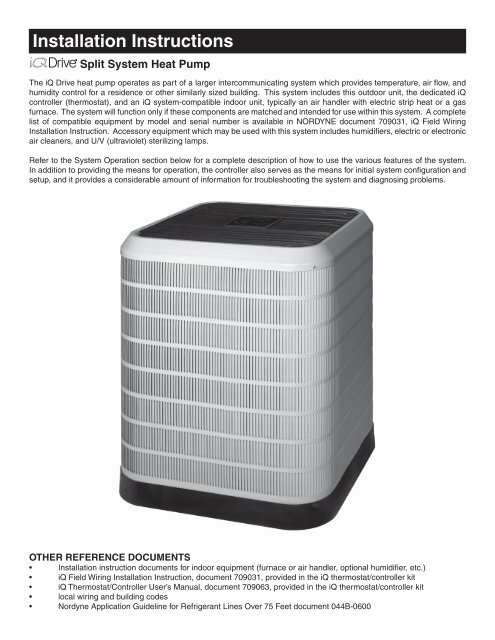
Installation InstructionsSplit System Heat PumpThe <strong>iQ</strong> Drive heat pump operates as part of a larger intercommunicating system which provides temperature, air fl ow, andhumidity control for a residence or other similarly sized building. This system includes this outdoor unit, the dedicated <strong>iQ</strong>controller (thermostat), and an <strong>iQ</strong> system-compatible indoor unit, typically an air handler with electric strip heat or a gasfurnace. The system will function only if these components are matched and intended for use within this system. A completelist of compatible equipment by model and serial number is available in NORDYNE document 709031, <strong>iQ</strong> Field WiringInstallation Instruction. Accessory equipment which may be used with this system includes humidifi ers, electric or electronicair cleaners, and U/V (ultraviolet) sterilizing lamps.Refer to the System Operation section below for a complete description of how to use the various features of the system.In addition to providing the means for operation, the controller also serves as the means for initial system confi guration andsetup, and it provides a considerable amount of information for troubleshooting the system and diagnosing problems.OTHER REFERENCE DOCUMENTS• Installation instruction documents for indoor equipment (furnace or air handler, optional humidifi er, etc.)• <strong>iQ</strong> Field Wiring Installation Instruction, document 709031, provided in the <strong>iQ</strong> thermostat/controller kit• <strong>iQ</strong> Thermostat/Controller User’s Manual, document 709063, provided in the <strong>iQ</strong> thermostat/controller kit• local wiring and building codes• <strong>Nordyne</strong> Application Guideline for Refrigerant Lines Over 75 Feet document 044B-0600
2TABLE OF CONTENTSPREPARATION .................................................................................................................................................... 3Slab Mounting ................................................................................................................................................. 3Roof Mounting ................................................................................................................................................ 3ELECTRICAL CONNECTIONS ........................................................................................................................... 3Electrical Power Wiring ................................................................................................................................... 3Control Circuit Wiring ...................................................................................................................................... 4Recheck Wiring ............................................................................................................................................... 4REFRIGERANT LINE CONNECTIONS ............................................................................................................... 4Line Design and Routing ................................................................................................................................ 4Brazing ........................................................................................................................................................... 5System Evacuation ......................................................................................................................................... 5Refrigerant Charging ...................................................................................................................................... 5Alternate Procedure for Charging Heat Pump in Heating Mode ............................................................................... 6Alternate Procedure for Charging Heat Pump in Cooling Mode .....................................................................6SYSTEM SETUP USING THE IQ CONTROLLER ............................................................................................... 6General ........................................................................................................................................................... 6Screen Navigation .......................................................................................................................................... 7The Main Screen ............................................................................................................................................ 7Installer Settings ............................................................................................................................................. 71. System Confi guration ............................................................................................................................ 72. Accessories ........................................................................................................................................... 83. Dealer Information ................................................................................................................................ 84. Defrost Confi guration ............................................................................................................................ 85. Heat Off Delay ...................................................................................................................................... 96. Altitude Adjust ....................................................................................................................................... 97. Service Tests ......................................................................................................................................... 9The SERVICE INFORMATION Screens ....................................................................................................... 10Other Confi guration Entries .......................................................................................................................... 111. Minimum Heat Pump Operating Temp ................................................................................................ 112. Auto Changeover Time ....................................................................................................................... 123. Date and Time ..................................................................................................................................... 124. Program Schedule vs. Nonprogrammable .......................................................................................... 125. Dehumidifi cation ................................................................................................................................. 136. Humidity Settings ................................................................................................................................ 137. Smart Recovery .................................................................................................................................. 13System Operation: Quick Start ..................................................................................................................... 14System Startup Checkout and Troubeshooting ............................................................................................ 14SYSTEM DIAGNOSIS AND TROUBLESHOOTING .......................................................................................... 15Controller ...................................................................................................................................................... 15Outdoor Unit Inverter .................................................................................................................................... 16Outdoor Unit Interface Board (right side small circuit board) ........................................................................ 16Outdoor Unit EXV Board (left side small circuit board) ................................................................................. 16Interface Board (in G6 <strong>iQ</strong> furnace kit or air handler) ..................................................................................... 16Indoor Unit EXV Board ................................................................................................................................. 16Indoor Unit Constant CFM Motor Control Board ................................................................................................ 17Indoor Unit One- or Two-Stage G7 Furnace Board ...................................................................................... 17Indoor Unit <strong>iQ</strong> Modulating Gas Furnace Board ............................................................................................ 17Common Troubleshooting Issues .................................................................................................................. 17MAINTENANCE ................................................................................................................................................. 18FIGURES and DIAGRAMS ................................................................................................................................ 18
PREPARATIONBefore proceeding with installation of <strong>iQ</strong> heat pumpequipment, consult with the distributor and homeowner toconfi rm that the equipment listed on the order is what wasordered, and that it matches labeling on the equipmentpackaging.Next determine (including consultation with the homeowner)the intended/preferred location for placement of thecompressor/outdoor coil unit. Unit envelope dimensions areshown in Figure 1.This heat pump is designed for outdoor installation only.Unit placement must take into consideration the followingclearances: (a) A minimum of 18 inches must be providedbetween each of the four sides and any solid barrier or wallwhich might block free inlet air fl ow into the coil. A minimumclearance of 36 inches is required between multiple units.(b) The corner of the unit covered by the control accesscover must be clear enough to allow comfortable access bya serviceperson. (c) The top of the unit must be open andunobstructed to prevent recirculation of outdoor fan dischargeair, particularly for air conditioning usage. A minimumdistance of 4 feet overhead clearance is recommended. Donot locate the unit in a pit with high walls on all sides.Locate the unit away from overhangs which would allowwater runoff or ice to fall directly onto the heat pump. Avoidplacing the unit near sidewalks or walkways to avoid possibleicing from defrost cycles. In low temperature climates, placethe unit where it is not directly in prevailing winds. Avoidplacing the heat pump near sleeping quarters or windows.As the unit goes through defrost cycles, a change in soundwill occur.Slab MountingThe preferred unit mounting is on an outdoor slab (concreteor plastic), on the ground, in an area with good drainageunlikely to be affected by heavy runoff, ground settling, ordeep snowdrift accumulation. The support slab shouldbe level. If the area is subject to heavy snowfall or driftaccumulation, the use of a snow stand is recommended aswell. Make sure that the drain holes in the bottom of the unitare not obstructed.Roof MountingThe method used for roof mounting should be designed soas not to overload roof structures nor transmit noise to theinterior of the structure. Refrigerant and electrical lines shouldbe routed through suitably waterproofed openings to preventleaking into the structure. Make sure that the roof structurecan adequately support the weight of the equipment. Consultlocal building codes for rooftop installations.Once a location has tentatively been selected, trace routingof new (or pre-existing) refrigerant lines (two), and powerand control wiring. See further discussion below.• maximum recommended length for refrigerant lines: 100feet• maximum elevation difference, compressor base toindoor coil base (compressor higher): 50 feet An oil trapis required for elevations exceeding 50 feet• maximum elevation difference, compressor base toindoor coil base (compressor lower): 50 feet An oil trapis required for elevations exceeding 50 feet• refrigerant lines should NOT be buried (in concrete orotherwise)• Refer to <strong>Nordyne</strong> Application Guideline for RefrigerantLines Over 75 Feet document 044B-0600, for pipingdetailsOnce the above information has been confi rmed and potentialquestions regarding location, refrigerant line routing, andwire routing have been resolved, proceed with unpacking theequipment. It is strongly recommended that inspection of thehardware be performed prior to bringing it to the installationsite. Inspect for cosmetic as well as functional damage (suchas obvious holes or gaps in tubes and joints, cut or pinchedwires or wire insulation).Confi rm that the <strong>iQ</strong> heat pump unit package includes thefollowing:• the coil/compressor/control unit itself• a packet including these instructions and one fi lter-drierNOTE: The thermostat/controller which is required for systemoperation is part of a separately purchased kit.ELECTRICAL CONNECTIONSWARNINGELECTRIC SHOCK HAZARDDisconnect all electrical power at maincircuit box before wiring electrical powerto the outdoor unit. Failure to follow theseinstructions may result in electric shock ordeath.Electrical Power WiringElectrical power wiring shall comply with the currentprovisions of the National Electrical Code (ANSI/NFPA 70)as supplemented by applicable local building codes. Theinstaller should become familiar with the wiring diagrambefore making electrical connections to the outdoor unit. Anequipment wiring diagram is included in this instruction andinside the unit control panel cover. Refer to the unit ratinglabel located on the exterior of the control box cover foroperating voltage, minimum circuit ampacity, and maximumfuse size. See Table I for wire sizing.3
4COPPER WIRE SIZE - AWG (1% Voltage Drop)Supply Circuit AmpacitySupply Wire Length - Ftup to 50 51 - 100 101 - 150 151 - 20015 14 10 8 620 12 8 6 425 10 8 6 430 10 6 4 435 8 6 4 340 8 6 4 345 6 4 3 250 6 4 3 2Wire Sized based on N.E.C. for 60°C type copper conductorsTable I. Copper Wire Ampacity Tables1) A properly sized branch circuit and disconnect switchmust be installed where it is easily accessible and withinline of sight of the outdoor unit.2) Remove the control panel cover. Route the power andground wires (3 wires, including earth ground) from thedisconnect box to the unit. Use of outdoor shieldedconduit (metal lined Sealtite®) is required. The electricalconduit opening is located on the lower left corner of thecontrol box.3) Connect the power wires to L1 and L2 box lugs of thecontactor, and the ground wire to the grounding lug tothe left of the contactor. See Figures 2 and 3. Onlycopper wires should be used.4) Replace the control panel cover before applying power.Control Circuit WiringThe heat pump is designed to operate with a 24 VAC ClassII control circuit. Control circuit wiring must comply with thelatest version of the National Electrical Code (ANSI/NFPA70) as supplemented by local building codes.In general, 24 VAC control power and communication buswiring must be run to interconnect the thermostat/controller,the indoor unit, and the outdoor unit. The “hub” of this networkand source of the 24 VAC is located within the indoor unit (airhandler or furnace). Refer to <strong>iQ</strong> Drive System Field WiringInstructions, NORDYNE document 709031 shipped with thecontroller, for connection of control wires to the indoor unitand for description of other indoor fi eld wiring, including tothe controller.Five (5) wires must be run between the indoor unit and theoutdoor unit (2 for 24 VAC power and 3 for communications).Use one shielded cable (3 or more conductors) forcommunications only, and a separate cable or pair of wiresfor control power. Refer to wiring diagram Figure 4 and TableII.1) Pass the 5 control wires into the hole in the lower rightside of the control panel of the outdoor unit, into theseparate low voltage wiring compartment. See Figures5 and 6.2) Locate the 5 corresponding factory-wired leads withstripped ends. Assure that each of these 5 wires (on thefactory wiring side of the wire connections) loops aroundand through the “donut” (toroidal choke). Refer to Figure7 which shows one wire making a single loop.3) Connect each of the 5 fi eld-run wires to its factory-wiredcounterpart using a wire nut, as indicated in Figures 4,5and 6.4) Replace the control panel cover before applying power.IndoorInterfaceBoardTerminalCommunication WiringIndoorInterfaceBoard plugwire colorOutdoor unitwire colorOutdoor InterfaceBoard Terminal(RHS circuitboard)DX+DX-YELWHTYELWHT3 pin 3 wire whiteconnector plug atRHS circuit boardGND GRN GRNterminal“INDOOR”R (screw)C (screw)Control Power Wiring[no factorywire][no factorywire]REDGRY“R” terminal screw(contactor coil,RHS)Table II. Control Wiring to Outdoor <strong>iQ</strong> Heat Pump UnitIMPORTANTIt is critical that the wires meant to connectto 24 vac control power (RED and GRAYwires) are not mistakenly connected to thecommunication bus wires (YEL, WHT, GRN).24 volts applied to the communication buswill damage the equipment.Recheck WiringCheck that wire routing is correct and connections are securefor all power and control wiring.REFRIGERANT LINE CONNECTIONSLine Design and RoutingRefrigerant lines must be connected by a licensed EPAcertifi ed technician following sound established installationpractice. Once the heat pump location has been determinedand the unit set in place the refrigerant lines should be routedand connected.• Refrigerant lines should follow a direct path from theindoor coil to the outdoor unit avoiding sharp bends.When lines pass through walls, make sure to properlyseal and support them so that vibration is not transmittedto the structure.• Refrigerant tubing should be supported in a mannerwhich assures that the tubing will not vibrate or wear as
a result of contact with sharp materials or edges duringsystem operation.• Lines must be clean refrigeration-grade copper.• Avoid removing caps and plugs from the heat pump orlines until they are ready to be connected.• Insulate the vapor line with refrigerant line insulation ¼”wall thickness or greater.Proper system performance and oil management dependon properly selecting the liquid and vapor line sizes. Referto Table III for the proper size of fi eld supplied lines. Themaximum allowable refrigerant line length is 100 ft.Line SetLength-024K Units-036K UnitsVapor Lineup to 24 ft. 25 to 39 ft. 40 to 75 ft.75 to 100ft.LiquidLineup to 100ft.3/4 in. 7/8 in. 7/8 in. 1 1/8 in. 3/8 in.(19 mm) (22 mm) (22 mm) (29 mm) (10 mm)3/4 in. 7/8 in. 1 1/8 in. 1 1/8 in. 3/8 in.(19 mm) (22 mm) (29 mm) (29 mm) (10 mm)7/8 in. 7/8 in. 1 1/8 in. 1 1/8 in. 3/8 in.-048K Units(22 mm) (22 mm) (29 mm) (29 mm) (10 mm)Table III. Permissible Refrigerant Line SizesThe maximum vertical elevation between the heat pump andindoor coil is 50 ft. Systems that require more elevation willneed to have an oil trap installed in the vapor line. Refer to<strong>Nordyne</strong> Application Guideline for Refrigerant Lines Over 75Feet (document 044B-0600) for piping details.A fi lter drier is supplied with the heat pump. It is required andrecommended that it be installed near the indoor coil.It is recommended to replace existing refrigerant lines thatwere previously used for an R-22 system. If the lines are notreplaced, they must be properly fl ushed by a licensed EPAcertifi ed technician in accordance with the manufacturer’sinstructions and established procedures.BrazingUse the appropriate safety equipment while brazing. Itemssuch as gloves, safety glasses, proper ventilation, and a fi reextinguisher should be used.1. Route the refrigerant lines from the indoor coil to theservice valves on the heat pump. Avoid sharp radiusbends and turns.2. Make sure that the vapor line is properly insulated for theentire length of the run for maximum system effi ciency.Improper insulation may also create condensation andresult in water damage to the equipment and buildingstructure.3. Remove the valve cores from the heat pump servicevalves. Wrap the valves completely with wet ragsto protect them from overheating during the brazingoperation.4. Connect both the vapor and liquid lines. Tubes should beround, de-burred and free of debris. Use a phosphorousand copper or silver brazing alloy for the joints. Do notuse soft solder with a low melting point.5. Connect the indoor lines according to the indoor unitinstructions. The indoor coil will require the same alloysand wet rags to protect the sensors from excessive heaton the refrigerant lines.6. Allow the service valves to cool and replace the valvecores.7. Leak test the connections using low pressure drynitrogen.System Evacuation1. Connect the refrigerant gauge manifold to both thevapor and liquid service valves. See Figure 8. Connectthe center port to the vacuum pump.2. Open both manifold valves and start the vacuum pump.After a short time, it is recommended to close themanifold valves and stop the vacuum pump to look fora rapid loss of vacuum. Loss of vacuum indicates thatthere is a leak in the system. Repeat the leak test ifrequired.3. Evacuate the system to at least 500 microns to removenon-condensables and water vapor. Close the manifoldvalves and remove the vacuum pump.4. Connect the refrigerant tank to the center manifold portof the gauge set. Pressurize the system enough to breakthe vacuum.5. Open both service valves by turning the valve stems ¼turn counterclockwise. The stem will be in line with thetubes. Replace the stem caps and tighten. Proceed withRefrigerant Charging section.WARNINGThe heat pump system contains liquidand gaseous refrigerant under pressure.Adjustment of refrigerant charge shouldonly be done by a qualified, EPA certifiedtechnician thoroughly familiar with this typeof equipment. Under no circumstancesshould the homeowner attempt to install and/or service this equipment. Failure to complywith this warning could result in equipmentdamage, personal injury, or death.Refrigerant ChargingNOTE: The unit must be charged at a fi xed speed setting.For this purpose the thermostat/controller needs to be wiredand powered prior to charging. Using the thermostat, goto CHARGE MODE under SERVICE TESTS from theINSTALLER SETTINGS menu, described later in thisdocument. Select CHARGE MODE to add or verify systemcharge. In the CHARGE MODE screen, HEATING orCOOLING mode may be selected, depending upon whichmode of operation is more appropriate or convenient at thetime of charging.5
Notes:• The heat pump is factory charged for fi eld installed lines15 ft. in length with the matching indoor equipment.Adjustments to the refrigerant charge will be required forother length and tube sizes. For lines longer than 15 ftwith a 3/8” OD liquid line, add 0.52 oz. per ft.• Small variations in the temperatures and pressures arenormal due to differences in the installation.• Large variations in the temperatures and pressurescould indicate incorrect charge or another problem witha component in the system.The preferred method of charging is by weighing in theadditional refrigerant required. If a charging scale is notavailable, the next preferred charging method would be touse the sub-cooling method in cooling mode.Model:Factory Charge(for 15 ft. line set)Additional Chargefor 50 ft. line setAdditional Chargefor 100 ft. line set2 ton(-024K)10.7 lbs(171 oz)+ 1.1 lbs(18 oz)+ 2.8 lbs(44 oz)3 ton(-036K)12.7 lbs(203 oz)+ 1.1 lbs(18 oz)+ 2.8 lbs(44 oz)4 ton(-048K)12.7 lbs(203 oz)+ 1.1 lbs(18 oz)+ 2.8 lbs(44 oz)Table IV. Refrigerant Charge QuantitiesAlternate Procedure for Charging Heat Pump in CoolingMode (with outdoor temperatures above 60 °F) Based onSubcooling:While charging based on weight is preferred, this method isacceptable. Use this method when the outdoor temperatureis 60°F or higher to verify the correct charge in cooling mode.The indoor temperature should be between 70°F and 80°F.1. Connect the gauge manifold to the liquid and vaporservice valves (Figure 8).2. Start the system in CHARGE MODE, COOLING. Allowthe system to run 15 minutes to stabilize.3. Record the liquid refrigerant pressure in psig at theservice valve.4. Record the liquid refrigerant temperature in °F at theservice valve.5. Using the temperature value recorded, determine thecorresponding liquid refrigerant pressure from the uppercurve (for cooling) in the charging chart (Figure 9).6. If the pressure measured in step 3 is less than therequired liquid refrigerant pressure determined in step5, then refrigerant needs to be added.7. If the pressure measured in step 3 is greater than therequired liquid refrigerant pressure determined in step5, then the system is over-charged.8. Add or remove charge from the system depending on themeasurements recorded. Allow the system to stabilizefor 15 minutes before taking the next readings.Alternate Procedure for Charging Heat Pump in HeatingMode (with outdoor temperatures below 60 °F) Based onSubcooling:Use this method when the outdoor temperature is 60°F orlower to estimate the correct charge in heating mode. Theindoor temperature should be between 65°F and 75°F.The preferred method of charging is by weighing in theadditional refrigerant required. If a charging scale is notavailable, the correct charge can be estimated by this method.Refrigerant can be stored in the receiver and accumulatorsand result in an over-charged system. If it is necessary touse this method, follow up service should be scheduled whenthe temperature is above 60°F, and then charge should beverifi ed in cooling mode.1. Connect the gauge manifold to the liquid service valveand suction service port located at the left side of theaccess panel above the liquid service valve. See Figure 8.2. Start the system in CHARGE MODE, HEATING. Allowthe system to run 15 minutes to stabilize.3. Record the liquid refrigerant pressure in psig at theservice valve.4. Record the liquid refrigerant temperature in °F at theservice valve.5. Using the temperature value recorded, determine thecorresponding liquid refrigerant pressure from the lowercurve (for heating) in the charging chart (Figure 9).6. If the pressure measured in step 3 is less than therequired liquid refrigerant pressure determined in step5, then refrigerant needs to be added.7. If the pressure measured in step 3 is greater than therequired liquid refrigerant pressure determined in step5, then the system is over-charged.8. Add or remove charge from the system depending on themeasurements recorded. Allow the system to stabilizefor 15 minutes before taking the next readings.SYSTEM SETUP USING THE IQ CONTROLLERIMPORTANTIt essential that the wires meant to provide 24volts to the outdoor unit are not mistakenlyconnected to the communication terminals.Check again before you apply power!GeneralPower up the entire system with the <strong>iQ</strong> controller (thermostat)installed in its base. The controller will be of use to theinstaller for the following general purposes:• Confi guring the system using INSTALLER SETTINGSscreens (required)• Running system service tests (recommended)• Using service information screens to examine anddiagnose system operation (very helpful, if needed)• Setting options and features which are not typically usedor understood by the homeowner (recommended)6
• Setting options and features with the homeowner’soversight in an effort to train him/her (suggested)The following descriptions of the controller apply specifi callyto software Version 5.0. A summary of the controller menustructure is provided in Figures 10 & 11. NOTE: This guidelineis not intended to be a comprehensive substitute for proper<strong>iQ</strong> Drive system training (required).Screen NavigationMoving between option categories on menu screens ormoving between possible values for any one option is doneusing the and keys. The line or value with a darkbackground behind the characters is considered “selected”.In order to change a selected option in most screens, or tosave a changed value, use the key. Use the key to backup into the previous screen in the menu/screen structure.The Main ScreenThe Main Screen is the normal display viewed on thecontroller. It prominently shows room temperature andoperating mode (e.g., COOL or HEAT) in large numerals andletters. Across the bottom line of the display are fi ve wordsor abbreviations (normally RH TEMP MODE FAN MENU)which represent selectable entry points into the menus. Theuser can always return to the main screen from any otherscreen by repeatedly pressing the key.76°HUMIDITY36RH3/13/09 12:18 PMOUTDOOR70TEMPMODEFAN AUTOHEATHEAT 62COOL 85FANMENUInstaller SettingsUsing procedures explained in <strong>iQ</strong> Drive training, go to theINSTALLER SETTINGS menu screen.INSTALLER SETTING<strong>SS</strong>YSTEM CONFIGURATIONACCE<strong>SS</strong>ORIESDEALER INFORMATIONSERVICE TESTSRESTORE DEFAULTSDEFROST CONFIGHEAT OFF DELAYALTITUDE ADJUSTOther than in the splash screen displayed when power isfi rst applied to the controller, this is the only screen whichdisplays the controller software version number.NOTE: It is important that any settings or service tests whichare appropriate be made at the time of system installation.1. System ConfigurationAny time “CONFIGURATION NEEDED” appears at the top ofthe Main Screen, the user must proceed through the SYSTEMCONFIGURATION screens, even if no changes to values oroptions are necessary. This will occur when installing a newthermostat or moving a thermostat to a different type of <strong>iQ</strong>system. The outdoor unit should be powered up whenconfirming or entering system configuration.With the fi rst line SYSTEM CONFIGURATION selected,press the key to proceed through the system confi gurationscreens. The next screen, titled SYSTEM CONFIGURATION,provides a read-only summary of the confi guration (asdetected, and otherwise showing either defaults or previouslyconfi gured information).SYSTEM CONFIGURATIONOUTDOOR SYSTEM2 TONHEAT PUMP - IQWITH1 STG GAS FURNACEBLOWER TYPE BCOMMUNICATIONINDOOR UNIT - OKOUTDOOR UNIT - OKThe words under OUTDOOR SYSTEM and WITH describethe system components as automatically detected by thecontroller. Both entries under COMMUNICATION shouldshow “OK”. If “CHECK” appears, it is an indication thateither communication wiring is incomplete or incorrect,or the outdoor unit is not powered up. Proceed throughsubsequent screens by using either the or key (indicatedby “NEXT”).The following table indicates the information that may beor needs to be manually confi gured or confi rmed by theinstaller. (Information not listed is automatically determined.)If necessary, check the ratings of the indoor unit beforeproceeding.IQ DRIVE REV 5.07
Indoor UnitElectric HeatG6 gas furnaceG7 single stage gasfurnaceItems Requiring Manual Configuration (orConfirmation)Heat type, number of stages, stagingdifferentials, kWHeat type, number of stages, 1 st stage startdifferential, furnace input rate, furnace rise. If2-stage: 2 nd stage differential1 st stage start differential, furnace riseACCE<strong>SS</strong>ORIESAIR FILTERHUMIDIFIERUV LAMPAIR CLEANERG7 two stage gasfurnaceModulating MQ gasfurnace1 st stage start differential, 2 nd stage differential,furnace riseFurnace riseTable V. System Configuration Entry SummaryFor MQ modulating <strong>iQ</strong> gas furnaces only, an additional screentitled “OUTDOOR SYSTEM” will appear after the SYSTEMCONFIGURATION summary screen. “HEAT PUMP-IQ”should appear on the second line; no other option may beselected in this screen. Press the key to proceed.OUTDOOR SYSTEMHEAT PUMP - IQCAPACITY (TONS)-STAGES-2ND STG DIFFERENTIAL-AIR FLOW, CFM PER TON-Proceed through the subsequent confi guration screenseither accepting or changing entries, until the INSTALLERSETTINGS menu is displayed again. This is an indicationthat confi guration has been completed.2. AccessoriesUse the or keys to select ACCE<strong>SS</strong>ORIES. Press thekey to enter the accessories submenus and screens. Thisset of screens allows the installer to trigger alerts (reminders)when periodic maintenance is recommended for any of thefollowing accessories:• Air fi lter• Humidifi er• U/V lamp• Air cleanerIf desired, set the maintenance alert timing for any of thesebased on either hours of operation or calendar time. Whentriggered by the passing of the selected time or operatinghours, the maintenance reminder message string will bedisplayed on the top of the Main Screen. In addition, at thebase of the Main Screen “CANCEL ALERT” will appear. Whenthis is selected and the key is pressed, the maintenancereminder message will be removed.8Making changes or entries under ACCE<strong>SS</strong>ORIES isoptional.3. Dealer InformationUse the or keys to select DEALER INFORMATION.Press the key to enter the dealer information summaryscreen, and submenus and screens. This set of screensallows the installer to enter text information which will bedisplayed on a SERVICE NEEDED display screen if apersistent fault occurs. The following items may be entered:• Brand name (Maytag, Frigidaire, NuTone, Broan,Tappan, Westinghouse, or custom)• Model Number• Contractor Name• Contractor Phone NumberDEALER INFORMATIONBRAND NAMEMAYTAGMODEL NUMBERFT4BI - 048KCONTRACTOR NAMEJOE’S HVACCONTRACTOR PHONE911 - 393 - 7777The entered dealer information summary screen accessiblehere will be available for future reference by a serviceperson(under INSTALLER SETTINGS > DEALER INFORMATION).Entry of this information is optional.4. Defrost ConfigurationUse the or keys to select DEFROST CONFIG. Pressthe key to enter the screen which allows changes to:• DEFROST TERMINATION TEMPERATURE. This is theoutdoor coil temperature value which, when reachedduring the defrost sequence, will signal the end of thedefrost phase during which the system heats up theoutdoor coil to melt accumulated frost. (Default value is75°F.)
• COIL DEFROST DELTA T. During heat pump heatingoperation a defrost sequence will be triggered whenthe outdoor coil temperature falls this amount below thetemperature it would operate at with a clear, unfrostedcoil. (Default value is 6°F.)DEFROST CONFIGDEFR TERMINATION TEMP75 DEG FCOIL DEFROST DELTA T6 DEG FUnder normal circumstances it is not necessary or advisableto change these from their default values.5. Heat Off DelayIf the system includes a G6 gas furnace, you may use theor keys to select HEAT OFF DELAY. Press the key toenter the screen which allows changes to the length of timethat the blower (indoor fan) will remain on after the furnacefl ame is extinguished. Under normal circumstances it is notnecessary or advisable to change this from its default valueof 120 seconds.6. Altitude AdjustIf the system includes an <strong>iQ</strong> modulating gas furnace, youmay use the or keys to select ALTITUDE ADJUST.Press the key to enter the screen which allows changes tothe installation altitude (feet above sea level). This entry isadvisable for the modulating gas furnace. Refer also to thefurnace Installation Instructions.7. Service TestsYou may use the or keys to select SERVICE TESTS.Press the key to enter the screen which allows access toa list of service tests. These tests provide an easy way forthe service person to operate the system in various modesfor operational confi rmation and diagnostic troubleshootingduring installation startup. The following fi ve options areavailable in the submenu.SERVICE TESTSCHARGE MODEFURNACE TESTSAIR COND RUN TESTSHEAT PUMP RUN TESTSDISCRETE OUTPUTSNOTE: While running the system from Service Tests isconvenient for some startup operations, much of the normalfault handling and diagnostic message functionality isdisabled.Within each test screen there may be more than one entrywhich can be changed. Select the desired entry to bemodifi ed using the and keys. The line or value witha dark background behind the characters is considered“selected”. Press the key to allow changing the selecteditem (its dark background will then blink). Set the desiredvalue for the item using the and keys, then press thekey to save it.The following is a brief description of the SERVICE TESTcategories:• CHARGE MODE – Runs the system at the proper speedfor checking and adjusting refrigerant charge. Selectthe mode as HEATING or COOLING, then change RUNfrom OFF to ON. The screen backlight will blink red.The user may navigate to other screens (e.g., SERVICEINFORMATION) during the process until ON in theCHARGE MODE screen is changed back to OFF andsaved. The red blinking backlight serves as a reminderthat the unit is operating in an abnormal (service) mode.Select OFF (from the list that includes ON and OFF) andSAVE ( ) when fi nished.• FURNACE TESTS – Runs the system at the selectedfi re level to allow confi rmation of proper operation. Thescreen backlight will blink red. A short list of instructions(reminders) is provided. Select START to run a singlestage furnace. Select LO FIRE or HI FIRE to run a twostage furnace. The user may navigate to other screens(e.g., SERVICE INFORMATION) during the process.The red blinking backlight serves as a reminder that theunit is operating in an abnormal (service) mode. SelectDONE (from the list that includes LO FIRE, HI FIRE,START, STOP) and SAVE ( ) when the test is complete,before leaving the screen for the last time.• AIR COND RUN TESTS and HEAT PUMP RUN TESTS– In these screens the unit can be made to run at a fi xedspeed regardless of room temperature. RUN can bechanged between OFF, MAX (speed), INTERMED(iatespeed), and MIN (speed). MAX speed is the same asthat used in charge mode. The screen backlight willblink red when anything but OFF is selected and saved.The user may navigate to other screens (e.g., SERVICEINFORMATION) during the process until RUN in thisscreen is changed back to OFF and saved. The redblinking backlight serves as a reminder that the unit isoperating in an abnormal (service) mode. This screenis primarily intended for test agency usage. Heat pumprun tests apply only to heat pump units. Select OFF andSAVE ( ) when fi nished.9
• DISCRETE OUTPUTS – When the unit is off, this screenallows the user to operate certain relay-driven outputs inthe system for diagnostic purposes: humidifi er (on theindoor interface board or blower control board), reversingvalve (on the outdoor interface board), indoor coil EXV(on the indoor interface board or blower control board),outdoor coil EXV (on the outdoor interface board), andcrankcase heater (on the outdoor interface board). Morethan one of these can be set to ON at the same time.Leaving the DISCRETE OUTPUTS screen will shut allof the listed outputs off.The SERVICE INFORMATION ScreensTypically, when any of these service tests is being performed,the serviceperson should check operation visually, withspecial instrumentation (if available), and view operationaldata on the SERVICE INFORMATION screens. Refer to <strong>iQ</strong>Drive training information for how to view these screens.SERVICE INFORMATIONFAULT STATUSCOMPRE<strong>SS</strong>OR STATUSOUTDOOR FAN STATUSINDOOR FAN STATUSFURNACE STATUSTEMPERATURE STATUSCLEAR FAULT HISTORYCALIBRATION DATACOMMUNICATION DATACCFM DATADEFROST STATUSCAPACITY CONTROLMost of the items on the SERVICE INFORMATION menu areself-explanatory by title. Some key features are the following(by item name):• FAULT STATUS. The top entry is ACTIVE FAULT. Thisshould show NO FAULT unless the last fault detectedhas not cleared after its 5 minute lockout period, or thefault condition still exists. The remainder of the screenshows a history of previous faults or conditions detected,with military time and date stamps for each. (Having thecorrect time and date confi gured is important in makingthis list useful.) Use the key to view the remainder ofthe last (most recent) 10 faults logged. Generally, faultlogging is not functional during Service Tests.FAULT STATUSACTIVE FAULTLOW PRE<strong>SS</strong>URE SWITCHFAULT HISTORY1LOW PRE<strong>SS</strong>URE SWITCHFLT 23:59 11/14/092OD UNIT COMM FLT#20 23:59 10/31/093NO FAULT• COMPRE<strong>SS</strong>OR STATUS. This screen should confi rmthe confi gured size as MODEL NUMBER (20 = 2 tons,30 = 3 tons, etc.) With correct confi guration only 20,30, or 40 should appear here. LOW PRE<strong>SS</strong>URE SWshows the state of the low pressure switch. Any COMPRERROR CODE number (normally 0) will be logged inthe FAULT STATUS screen in more easily understoodwording. The displayed information is read from theoutdoor unit.• OUTDOOR FAN STATUS. Any FAN ERROR CODEnumber (normally 0) will be logged in the FAULT STATUSscreen in more easily understood wording.• TEMPERATURE STATUS. This screen lists alltemperatures measured by the <strong>iQ</strong> system. TEMP ATTSTAT is the local temperature used for control, and itdisplays one decimal place without showing the decimalpoint (e.g., 704 = 70.4°).• CLEAR FAULT HISTORY. It is recommended that anyfaults that appeared during and as a consequence ofinstallation be cleared out before leaving.• CALIBRATION DATA. A Panasonic blower can berecalibrated at any time from this screen by pressingthe key. This may be done if a signifi cant changehas been made to blower discharge ducting or damperusage. This screen is not normally useful to an installer.Data is not displayed for type “B” blower motors.• COMMUNICATION DATA. This important screenindicates the status of communication with all elementson the <strong>iQ</strong> bus. All should show OK. If not, investigateand resolve communication wiring issues.10
OPTIONSPROGRAM SCHED USAGE4 SCHED EVENTS/DAYDEHUMIDIFICATIONONAUTO CHANGEOVER TIME60MINUTE<strong>SS</strong>MART RECOVERYOFFHEAT PUMP USAGE LIMITNOT BELOW 14Faccurate time and date stamp for any faults logged (duringinstallation checkout, for example) in FAULT HISTORY. Bydefault, the clock is in 12 hour format. This may be changedon the OPTIONS menu screen (see either of the above twoitems). Daylight Saving Time is automatically taken intoaccount but may be disabled from the SET DATE AND TIMEmenu screen.In order to set date and time, do the following:• From the Main Screen, press the or key to selectMENU at the bottom of the screen, then press the keyto see the Main Menu.• Use the or key to select the value under HEATPUMP USAGE LIMIT, then press the key to allowchanging the setting.• Use the or key to change the value (2°F increments),then press the key to save the setting.• Press the key multiple times to return to the MainScreen.2. Auto Changeover TimeThis adjustment enables AUTO mode, which allows thesystem to automatically switch between heating and coolingwithout having to touch the controller. Autochangeover timeis the delay (minimum time) between the end of coolingoperation and the beginning of heating operation (or thereverse). DISABLE removes AUTO as an available mode.Otherwise, the time may be selected from 15 to 120 minutes(default 60 minutes).In order to modify the value, do the following:• From the Main Screen, press the or key to selectMENU at the bottom of the screen, then press the keyto see the Main Menu.• Use the or key to select SETTINGS, then press thekey to enter the Settings menu.• Use the or key to select OPTIONS, then press thekey to enter the Options screen.• Use the or key to select the value under AUTOCHANGEOVER TIME, then press the key to allowchanging the setting.• Use the or key to change the value, then press thekey to save the setting.• Press the key multiple times to return to the MainScreen.3. Date and Time.Setting date and time early in the installation process not onlysaves the homeowner from having to do it, but provides an12• SET DATE AND TIME will be selected. Press the keytwo times.• Enter the year, month, day (date), hour, and minute onconsecutive screens. Use the or key to change anyvalue, and press the key to advance to the next. Aftersetting the minutes value, press the key to save thecomplete setting.• Press the key multiple times to return to the MainScreen.4. Program Schedule versus Nonprogrammable.While using “setback” program schedules are advisable totake advantage of potential economic and energy savings,some homeowners still prefer to perform setpoint adjustmentby exclusively using the and keys. The following settingprovides the nonprogrammable option or the option fordifferent numbers of events per day (2 or 4) on the programschedule.In order to set the program schedule option, do thefollowing:• From the Main Screen, press the or key to selectMENU at the bottom of the screen, then press the keyto see the Main Menu.• Use the or key to select SETTINGS, then press thekey to enter the Settings menu.• Use the or key to select OPTIONS, then press thekey to enter the Options screen.• The value under PROGRAM SCHED USAGE willbe selected. Press the key to allow changing thesetting.• Use the or key to change the value between “NONPROGRAMMABLE”, “4 SCHED EVENTS/DAY”, “2SCHED EVENTS/DAY”, and “2 EVENTS/D BUSINE<strong>SS</strong>”.Then press the key to save the setting. (The differencebetween “2 EVENTS/D BUSINE<strong>SS</strong>” and “2 SCHEDEVENTS/DAY” is only the name given to the time blockswithin a daily schedule.)• Press the key multiple times to return to the MainScreen.
• Use the or key to change the value between “OFF”(the default) and “ON”, then press the key to save thesetting.• Press the key multiple times to return to the MainScreen.System Operation: Quick StartThe following is a summary of the sequence for typicaloperation of the system.1. Set the date and time if not already set.2. Check the program schedule for desired “setback”, andmodify if desired.3. From the main screen, check/set the Fan operatingmode:• AUTO operates the fan (indoor blower) when the unitis cooling or heating. This is the “normal” setting.• ON operates the fan at the selected speed at alltimes. The selected speed may change when thecompressor, electric heat, or furnace is operating.• PROGRAMMED FAN operates the fan in AUTO orON as specifi ed in the program schedule.4. From the main screen, check/set the Mode:• COOL runs the heat pump as an air conditionerusing the cooling setpoint.• HEAT attempts to run the heat pump to provideheat using the heating setpoint. If (a) the outdoortemperature is below the Heat Pump Usage Limit,or (b) the heat pump cannot satisfy the load, or (c)the heat pump is disabled due to a fault, auxiliary(backup) heat will operate. If backup heat iselectric strip heat, it may operate along with andsupplementing the heat pump. If backup heat isa gas furnace, the furnace and heat pump will notoperate at the same time (except during defrost).If the outdoor coil temperature is below 35°F, demanddefrost is enabled. Under these conditions, a fi rsttime defrost will occur after approximately one halfhour of compressor operation. Subsequent defrostcycles may be triggered by a drop in outdoor coiltemperature or by a maximum time between defrostsof 6 hours. Refer to training material for details.• E HEAT will run the auxiliary heat (electric stripheat or gas furnace) using the heating setpoint anddisable the heat pump.• OFF terminates any of the above. Note thatequipment may not shut off immediately afterswitching to OFF due to various system limitations.Once put into the OFF mode, wait until the furnaceor compressor has shut off before selecting anothermode.5. Adjust the operating setpoint if desired using a temporaryhold (pressing the or key when the Main Screen isdisplayed).System Startup Checkout and TroubleshootingThe following is a summary of the sequence for typical fi rstoperation to check out the system. Reference is made toINSTALLER SETTINGS and SERVICE INFORMATIONdescribed above.1. Install system hardware as described in the individualcomponent installation instructions.2. Install power and control wiring to all system components,including the controller, in accordance with the <strong>iQ</strong> FieldWiring Installation Instructions.3. Perform pre-charge evacuation of fi eld-installedrefrigerant lines as described in preceding sections.4. Apply electrical power to the system (including the heatpump). The controller screen display backlight shouldcome on, and the “<strong>iQ</strong>” splash screen should appear. Ifit does not, trace the 24 vac control power to the “R”terminal on the thermostat. CONFIGURATION NEEDEDshould appear on the top line of the Main Screen (unlessthe thermostat had been previously used on a similar <strong>iQ</strong>system).5. Proceed with System Confi guration from the INSTALLERSETTINGS menu (described above). On the SYSTEMCONFIGURATION screen verify that the using size (2ton, 3 ton, or 4 ton) is correct as indicated. If the wrongvalue is shown, the inverter may require re-initialization.Contact the service representative of the distributor inthis case.On the same screen, the entries under COMMUNICATIONshould be followed by “OK”. If “CHECK” appears fora communication item, go to the COMMUNICATIONSTATUS screen (in the SERVICE INFORMATIONmenu, described above), and view which elementsare not communicating. Trace and check the threecommunication wires throughout the system. If isolatinga communication problem proves to be diffi cult, itmay be useful to disconnect all communication wiresexcept those which link the thermostat and the noncommunicatingelement.6. If COMMUNICATION STATUS was not checked duringthe previous step, check it at this time. All listed itemsshould show a status of “OK”. If any show “BAD”,determine the source of the problem as indicated in theprevious step, and resolve.14
7. Set date and time as described above. This will provide a“time stamp” for any fault which may arise during systemcheckout.8. If the installation includes a new gas furnace, checkout its operation fi rst. This may be best accomplishedfrom FURNACE TESTS under SERVICE TESTS fromthe INSTALLER SETTINGS menu (see above). Followsteps instructions provided in the furnace’s installationinstructions. Be sure to verify blower operation duringthe test.9. If the outdoor temperature is above 60°F (14°C), testthe refrigerant system running in cooling mode fi rst.If the outdoor temperature is between 12° and 60°F(-11 and 14°C), test the refrigerant system running inheating mode fi rst. This may best be accomplishedfrom CHARGE MODE under SERVICE TESTS from theINSTALLER SETTINGS menu. Follow the refrigerantcharge adjustment procedure explained above. Notethat if a fault is determined in the outdoor equipment,the backup heating means (electric strip heat or gasfurnace) will start instead.10. When charge adjustment is completed (if required), runthe heat pump in both cooling and heating modes. Thismay also be done using SERVICE TESTS althoughsome diagnostic messages are disabled in that method.11. Check the FAULT STATUS screen (described above)for any faults logged during the startup process. Anymessage listed as “ACTIVE FAULT” refers to a conditionwhich either still exists or occurred within the preceding 5minutes. Every fault or notifi cation should appear in theFAULT HISTORY log which starts on the same screen.The last 10 faults to have occurred are retained in thislist. Each new item pushes other logged faults down inthe list. The second line associated with each of the 10entries includes the time and date of detection. Whilethe wording of fault messages is intended to provide areasonable indication as to the responsible condition,the information conveyed by the abbreviated wordingis limited. Consequently the installer should refer totraining literature for further information in understandingfault messages.12. If needed, make use of information provided belowunder Troubleshooting: What to Expect with NormalOperation.13. Independently confi rm operation of any accessoriesinstalled with the heat pump system following instructionsprovided with that equipment.14. Complete the remainder of confi guration settings andentries as specifi ed above under Installer Settings andOther Confi guration Entries.SYSTEM DIAGNOSIS AND TROUBLESHOOTINGThe following is a summary of normal and abnormal operationfor typical startup to check out the system. Reference is madeto INSTALLER SETTINGS and SERVICE INFORMATIONscreens described above. Refer to training literature formore details.Diagnostic information for the heat pump can be obtainedfrom all of the following sources:• Controller displays. Refer to training materials forinterpretation of fault messages which appear on theMain, Fault Status, and Service Needed screens.• Refrigerant system pressure and temperaturemeasurements (using standard fi eld serviceinstrumentation)• LED indicator lights on each of the system’s circuitboards (see below).Controller:Normal - As soon as 24 vac power is applied, the bluebacklight of the controller should light up. The “<strong>iQ</strong>” splashscreen will display the software version. If the SystemConfi guration procedure has not been performed yet forthis system-controller combination, “CONFIGURATIONNEEDED” will be displayed across the top (alternating withother information).If the system has a Type “P” blower motor (shown on SYSTEMCONFIGURATION and INDOOR FAN STATUS screens),used in air handlers or G6 gas furnaces, the blower will selfcalibratefor 60 seconds as soon as System Confi guration iscompleted.All communications links in COMMUNICATION DATAshould show “OK”. All information displayed in the SystemConfi guration screen should be accurate.Abnormal – If the display is not lit, check that 24 vac is beingprovided between the “R” and “C” terminals in the thermostat’sback connection plate. If not, trace the connection of allcontroller wires back to the indoor unit (furnace or airhandler). Check that connections are in accordance withfi eld wiring diagrams and instructions.If a SERVICE NEEDED screen with a red backlight isdisplayed, a fault has been detected. A brief description ofthe fault is displayed on the screen. Access to the FAULTSTATUS screen is permitted.If communication with the outdoor unit is OK but the unitsize (in tons) shown on the System Confi guration screen inwrong, contact the service representative of the equipmentdistributor. The inverter may not have undergone itsinitialization procedure, performed at the factory.15
Outdoor Unit Inverter:16WARNINGELECTRIC SHOCK HAZARD!Disconnect power before servicing the outdoorunit. Failure to follow these instructions mayresult in electric shock or death. Troubleshootingthe outdoor unit may require thatpower be restored with the control panelcover removed. Become familiar with thecontrol panel and hazardous voltage areasbefore proceeding.Time is required for inverter voltage to bleeddown after removal of line power. Wait at least60 seconds after removing line voltage beforetouching any inverter parts or wiring.Normal – Examine the following with the control panel coveroff. Note the two smaller circuit boards mounted on a metal“bridge” over the inverter. The red LED behind the upperright side of the bridge should be lit and on steady whenpower is applied to the inverter. Refer to Figures 2 and 12.Abnormal –The red LED behind the upper right side of thebridge is not lit. In this case, power is not being provided tothe inverter. Check that line voltage is being applied to thebottom of the contactor. If so, check that 24 vac is beingprovided across the contactor coil. If not, check the controlpower wiring (RED and GRY wires) for 24 vac. Check thatthe high pressure switch is closed. A fault indicating ODUNIT COMM FAULT or OD UNIT LOST POWER would alsoresult from no line voltage applied.The red LED behind the upper right side of the bridge islit but blinking. This indicates that the inverter is poweredup and that it detects a fault condition. If the controllerdoes not display a fault message, put the unit into HEAT orCOOL mode, and a message will be displayed. Note thatwhen line power is removed, this LED will blink for about 1minute before going out. Check that the 3- and 4-positioncommunication plugs are connected to the terminals marked“INVERTER” and “INDOOR” on the right side of the outdoorinterface board.Outdoor Unit Interface Board (right side small circuitboard):Normal – Refer to Figure 13. The red LED at the upperleft of this board should do a “heartbeat” blink, consistingof a double-blink followed by a pause, repeated. Note 4other LEDS towards the lower edge of the board. Whenthe compressor is off, the 3rd LED from the right should beon (crankcase heater). When the compressor is runningin heating, the 2nd LED from the right should be on (EXVenabled to open). When the unit is heating and in a defrostcycle, the 1st and 4th LEDs from the right should be on.When the compressor is running in cooling, the right-mostLED should be on (reversing valve is energized).Abnormal – If no LEDs are lit on the board, 24 vac controlpower is not being provided across the “R” and “C” terminals.Check for this voltage between the left-most two screwterminals (labeled R and C).Outdoor Unit EXV Board (left side small circuit board):Normal – Refer to Figure 14. The green LED at the upper leftof this board should be steadily on, except that a blink at aregular rate can be expected during cooling operation.Abnormal – If the green LED is not lit, the EXV board isnot getting 24 vac power from the interface board next to it.Check for 24 vac between R and C on the interface board,and check that the tabs marked “R” and “C” on the interfaceboard are wired to “R” and “C” on the EXV board (red andgray wires, respectively). These should not be cross-wired.If the green LED is blinking at a regular rate during heatpump heating, it indicates that one of the two EXV sensorsis reading out of range. Refer to training literature for sensorinterpretation and troubleshooting.If the green LED is blinking at a non-uniform rate (heartbeat),it indicates that the board has been placed in the ManualMode. Hold down the small black button on the board formore than 3 seconds to return it to automatic control mode.Indoor Unit Interface Board (in G6 <strong>iQ</strong> furnace kit or airhandler)Normal – The red LED at the upper left of this board shoulddo a “heartbeat” blink, consisting of a double-blink followedby a pause, repeated. Note 4 other LEDS towards the loweredge of the board. When the equipment is off, none of theLEDs should be on. If the furnace or electric strip heat ison, 3rd LED or 3rd and 4th LEDs from the right should beon (fi rst and second stage auxiliary heat). When the unit iscooling the right-most LED should be on (EXV enabled toopen). If humidifi cation is called for, the 2nd LED from theright should be on.Abnormal – If no LEDs are lit on the board, 24 vac controlpower is not being provided across the “R” and “C” terminals.Check for this voltage between the left-most two screwterminals (labeled R and C).Indoor Unit EXV Board:Normal – The green LED at the upper left of this boardshould be steadily on, except that a blink at a regular ratecan be expected during heat pump heating operation.Abnormal – If the green LED is not lit, the EXV board is notgetting 24 vac power from the interface board. Check for24 vac between R and C on the interface board, and checkthat the tabs marked “R” and “C” on the interface board arewired to “R” and “C” on the EXV board. These should not becross-wired.
If the green LED is blinking at a regular rate during cooling,it indicates that one of the two EXV sensors is reading outof range. Refer to training literature for sensor interpretationand troubleshooting.If the green LED is blinking at a non-uniform rate (heartbeat),it indicates that the board has been placed in the ManualMode. Hold down the small black button on the board formore than 3 seconds to return it to automatic control mode.Indoor Unit Constant CFM Motor Control Board:Normal – The red LED near the top of the board shouldbe on steadily. The green LED near the top of the boardshould have a “heartbeat” blink, consisting of a double-blinkfollowed by a pause, repeated. Of the four LEDs towards theleft side of the board, the lowest one marked “H” should beon when humidifi cation is called for.Abnormal – If the green LED near the top of the board is notlit, the board is not connected to the communication networkproperly. If the red LED near the top of the board is notlit, the board is not getting 24 vac control power from thefurnace board.Indoor Unit One- or Two-Stage G7 Furnace Board:Normal – The red and green LEDs should be on steadily.When the furnace is on and a fl ame is detected, the amberLED should be on.Abnormal – The LEDs will provide a diagnostic code throughtheir blink pattern. Refer to furnace Installation Instructionsfor detailed troubleshooting.Indoor Unit <strong>iQ</strong> Modulating Gas Furnace Board:Normal – The red LED should be on steadily. The green LEDnear the top of the board should have a “heartbeat” blink,consisting of a double-blink followed by a pause, repeated.When the furnace is on and a fl ame is detected, the amberLED should be on.Abnormal – The LEDs will provide a diagnostic code throughtheir blink pattern. Refer to furnace Installation Instructionsfor detailed troubleshooting. If the green LED alone is notlit, the board is not connected to the communication networkproperly.Common Troubleshooting Issues:Compressor Does Not Start Immediately• For normal operation without changing modes ofoperation, the compressor will not restart until 5minutes (the minimum off time) have expired since itshut off last.• A minimum demand of 0.5°F is required before theheat pump (heating or cooling) will start up.• The system will wait 5 minutes following detection ofa fault condition before attempting a restart.Compressor Does Not Shut Off Immediately• For normal operation without changing modes ofoperation, the compressor will not shut off until 5minutes (the minimum run time) have expired sinceit started last.The Outdoor Fan Does Not Shut Off When the CompressorDoes• For normal operation the outdoor fan is designed torun for 30 seconds after the compressor shuts off.In Cooling, the Blower Slows Down and the Unit Is NotResponding to Room Temperature• Slowing of blower speed and suspension of normalcapacity control will occur when the unit goes intoDehumidifi cation. If conditions for dehumidifi cationpersist, the unit will run cycles of 10 minutes indehumidifi cation, 5 minutes in normal cooling(responding to room temperature).In Heating, the Unit Appears to be Cooling• During heat pump heating when the outdoortemperature is in the mid-30’s (°F) or lower, the unitwill periodically go into a Demand Defrost operation.After power to the controller is turned on, the fi rstdefrost may occur as soon as 34 minutes afterstartup. Subsequently, defrost will be determined byoutdoor coil temperature or by the maximum timebetween defrosts of 6 hours (if the coil temperatureis low enough).In Heat Pump Heating, the Furnace Runs At the SameTime• The indoor (backup) heating system will operateduring defrost cycles. (See above item.)In Heating, the Furnace or Electric Heat Runs Instead ofthe Heat Pump• The indoor backup heat equipment will run insteadof the heat pump if (a) the outdoor air temperatureis below the Minimum Heat Pump Usage Limit, (b)the heat pump is in a fault condition, or (c) the heatpump is not able to satisfy the demand (after a timedelay).The System Is In AUTO Mode, but It Won’t Switch QuicklyFrom Heating to Cooling (or the Reverse)• There is a confi gurable delay (Auto ChangeoverTime) between operating in heating and restartingin cooling (or the reverse) when in AUTO mode. Thedefault delay for this changeover is 60 minutes.Although There Is a Large Demand At Startup, theCompressor Only Runs at Medium Speed• Regardless of demand the system will always startand run at an intermediate speed for one minute.Subsequently the speed may increase signifi cantly.17
Humidification or Dehumidification Setpoints Are NotBeing Satisfied• The fi rst priority of the system is to achievethe temperature setpoint(s). While under mostcircumstances it will also satisfy humidity setpoints,its ability to accomplish this is signifi cantly affectedby a variety of installation-based factors andcircumstances.MAINTENANCEIMPORTANT:Be certain the electrical power to theoutdoor unit and the furnace or air handleris disconnected before doing the followingrecommended maintenance.• Inspect the indoor air fi lter monthly. Clean or replace itat the start of each heating and cooling season or whenan accumulation of dust or dirt is visible. If the indoorcoil needs to be cleaned, contact a qualifi ed servicetechnician.• Inspect the condensate disposal line from the indoor coilat the beginning of the cooling season to make sure it isnot obstructed.• Remove any leaves, grass clippings, and debris fromthe outdoor unit coil, being careful not to damage thealuminum fi ns. Dirt may be cleared from the coil by usinga water hose directed through the discharge fan grilletoward the outside of the unit.• Have a yearly inspection by a qualifi ed service technicianto ensure that the system is performing at its optimallevel.FIGURESandDIAGRAMS18"EXTERIOR WALL18"18"CONTROLPANEL18"18Figure 1. Unit Envelope Dimensions
Inverter(black plastic case)}}OutdoorEXV BoardOutdoorInterface BoardContactorLow VoltageControl WiringCompartment19Figure 2. <strong>iQ</strong> Drive Heat Pump Control Panel
Figure 3. Power Wiring Connections20
<strong>iQ</strong> DRIVE - HEAT PUMP (OUTDOOR SECTION)COMPR CSRREDYELLOWBLACK2XOD FANMOTORBLACKYELLOWREDLPS HARNE<strong>SS</strong>OD COIL TEMPSENSOR(FOR DEFROST)PRE<strong>SS</strong>URETRANSDUCEREXVSUCTION LINETHERMISTOR6-WIREHARNE<strong>SS</strong>P2 P3W V U 1 2 3 4 5 6 7 6 5 4 3 2 1CN3CN6CN7TA6TA5TA4EXV BOARDYPANASONICINVERTERR CGRAYREDCOIL TIFB2P3P4P2G-+R G-+ G-+C R R C CCH Y OCN8YELWHGN+ - G 2 1 4 3 2 1GNWHYLCN114-PIN3 WIRELOW PRE<strong>SS</strong>URESWITCHCOMPRDISCHGTEMPSENSOR3-WIREHARNE<strong>SS</strong>OUTDOORAMBIENTTEMPSENSORREDYELLOWREACTORTA7 TA8TA2 TA1REVERSING VALVE COILT1L1CONTACTORT2L2HIGH PRE<strong>SS</strong>.SWITCHGRAYREDGRAYBCCH RELAYCNOAWHITETA3GREENBLACK30ABLACKYELLOW30AYELLOW1XBLACKCRANKCASEHEATERFIELD WIRING TOINDOOR SECTIONGRAYLINE VOLTAGE (208/230)LEGEND:FIELD WIRINGLOW VOLTAGEHIGH VOLTAGEFigure 4. <strong>iQ</strong> Heat Pump Wiring Diagram21
Figure 5. Low Voltage Compartment Control Wiring ConnectionsGRNGRYREDWHTYELGNDDX-DX+CRFigure 6. <strong>iQ</strong> Heat Pump Control Wiring Outdoor Destinations22
SINGLE LOOP SHOWNFigure 7. Wire Looping Through a Toroidial ChokeSuctionService PortLiquid LineService ValveVapor LineService ValveFigure 8. Service Ports and Valves (Below Control Panel)23
Cooling Mode(Outdoor Temperature above 60 °F)5254753 Ton2 Ton4 TonRemove Refrigerant if above the curve425Liquid Pressure (psig)375325275Add Refrigerant if below the curve22517560 70 80 90 100 110 120 130Liquid Temperature (°F)380Heating Mode(Outdoor Temperature below 60 °F)3603 Ton2 TonRemove Refrigerant if above the curve4 Ton340Liquid Pressure (psig)320300280Add Refrigerant if below the curve26024075 80 85 90 95 100 105 110 115Liquid Temperature (°F)24Figure 9. Charging Charts for <strong>iQ</strong> Heat Pump
RHHUMIDITYHUMIDITY SETTINGSHUMIDIFYDEHUMIDIFYSET DATE AND TIMESET DATE AND TIMEAUTO DAYLIGHT SAVINGHOLD MENUVACATIONPERMANENTSET DATE AND TIMESET YEARAUTO DAYLIGHT SAVINGONOFFSET MONTHSET DAYVACATION HOLDHOLD TEMPERATURESET HOURVACATION HOLDHOLD UNTIL DATESET MINUTEVACATION HOLDHOLD UNTIL TIMENOTE: Bold Font Indicates Menu or Screen Title NameMain ScreenTEMP MODEFANMENUINSTALLERSETTINGSHOLD THISTEMPERATUREOPERATING MODEMENUOFFAUTOCOOLHEATE HEATFAN MENUAUTOONPROGRAMMED FANMAIN MENUSET TIME AND DATEHOLDPROGRAMFANMODESETTING<strong>SS</strong>ECURITY LOCKOUTPROGRAM MENUCOPY[list of days]EVERY DAYWEEKDAYSWEEKENDSFAN MENUAUTOONPROGRAMMED FANMODE MENUOFFAUTOCOOLHEATE HEATSETTINGS MENUSCREEN SETTINGSOPTIONSOFFSETSINTERMITTENT FANSECURITY LOCKOUTTEMP ADJUST ONLYTOTAL KEYPAD LOCKOUTENTER PIN NUMBERSERVICE INFORMATIONFAULT STATUSCOMPRE<strong>SS</strong>OR STATUSOUTDOOR FAN STATUSINDOOR FAN STATUSFURNACE STATUSTEMPERATURE STATUSCLEAR FAULT HISTORYCALIBRATION DATACOMMUNICATION DATACCFM DATADEFROST STATUSCAPACITY CONTROLPERMANENT HOLDHOLD TEMPERATUREFAULT STATUSCOPY FROMCOPY TOMONDAYTIME HEAT COOL FANSCHEDULE BLOCK 1SCHEDULE BLOCK 2SCHEDULE BLOCK 3SCHEDULE BLOCK 4(TYPICAL FOR EACH DAY OR GROUP OF DAYS LISTED)COMPRE<strong>SS</strong>OR STATUSOUTDOOR FAN STATUSINDOOR FAN STATUSFURNACE STATUSTEMPERATURE STATUSCLEAR FAULT HISTORYCALIBRATION DATACOMMUNICATION DATACCFM DATADEFROST STATUSCAPACITY CONTROLCOPY PROGRAM(Confirmation)SCREEN SETTINGSFAHRENHEIT OR CELSIUS12 OR 24 HOUR CLOCKCONTRASTINTERMITTENT FANBACKLIGHT ON TIMEOPTIONSPROGRAM SCHED USAGEDEHUMIDIFICATIONAUTO CHANGEOVER TIMESMART RECOVERYHEAT PUMP USAGE LIMITBACKUP HEAT RESPONSEOFFSETSINDOOR TEMPERATUREREMOTE INDOOR TEMPOUTDOOR TEMPERATURERELATIVE HUMIDITYHEAT ANTICIPATORINTERMITTENT FANFAN ON TIMEFAN OFF TIMEFigure 10. Controller Menu Structure: Main Screen25
SYSTEMCONFIGURATIONOUTDOOR SYSTEMHEAT PUMP-IQPANASONICBLOWER SYSTEM<strong>SS</strong>ELECT GAS OR ELECTRIC HEATSELECT ONE OR TWO STAGE<strong>SS</strong>INGLE STAGESTART DIFFERENTIALSTAGE 1ELECTRIC HEATKWACCE<strong>SS</strong>ORIESDEALERINFORMATIONSERVICE TESTSACCE<strong>SS</strong>ORIESAIR FILTERHUMIDIFIERUV LAMPAIR CLEANERG7 FURNACE SYSTEM<strong>SS</strong>INGLE STAGESTART DIFFERENTIALSTAGE 1TWO STAGESTART DIFFERENTIALSTAGE 1STAGE 2IQ MODULATINGGAS FURNACERISEGAS FURNACEINPUT RATERISETWO STAGESTART DIFFERENTIALSTAGE 1STAGE 2GAS FURNACEINPUT RATERISEINSTALLERSETTINGSAIR FILTERCHANGEHUMIDIFIERCHANGEUV LAMPCHANGEAIR CLEANERCHANGERESTOREDEFAULTSDEFROST CONFIGRESTOREDEFAULTSDEFROST CONFIGDEFR TERMINATION TEMPCOIL DEFROST DELTA TDEALER INFORMATIONBRAND NAMEMODEL NUMBERCONTRACTOR NAMECONTRACTOR PHONESELECT BRAND NAMEMODEL NUMBERCONTRACTOR NAMECONTRACTOR PHONESERVICE AIR CLEANERCUMULATIVE RUN TIMECALENDAR TIMESET CUMULATIVE RUN TIMESET CALENDAR TIME(TYPICAL FOR ALL 4 ACCE<strong>SS</strong>ORIES)HEAT OFF DELAYALTITUDE ADJUSTSET HEAT OFF DELAYSET ALTITUDESERVICE TESTSCHARGE MODEFURNACE TESTSAIR COND RUN TESTSHEAT PUMP RUN TESTSDISCRETE OUTPUTSCHARGE MODEFURNACE TESTSAIR COND RUN TESTSHEAT PUMP RUN TESTSDISCRETE OUTPUTSFigure 11. Controller Menu Structure: Installer Settings26
Inverter LED(to the left of blueDIP switch block)Figure 12. Inverter LED Location(Behind Interface Board, to the left of blue DIP switch block)CommunicationLEDDEF CCH Y RVFigure 13. Interface Board LED Locations27
PowerLEDFigure 14. EXV Board Green LED LocationINSTALLER: PLEASE LEAVE THESEINSTALLATION INSTRUCTIONS WITH THE OWNER.O’Fallon, MO¢<strong>708921</strong>(¤<strong>708921</strong>A<strong>708921</strong>A (Replaces <strong>708921</strong>0)Specifi cations and illustrations subject to changewithout notice and without incurring obligations.Printed in U.S.A. (07/09)