warning - Nordyne
warning - Nordyne
warning - Nordyne

You also want an ePaper? Increase the reach of your titles
YUMPU automatically turns print PDFs into web optimized ePapers that Google loves.
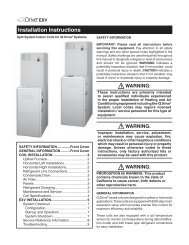
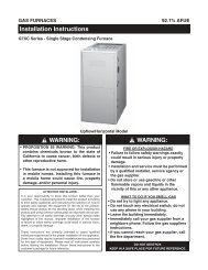
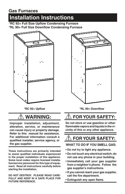
Gas FurnacesInstallation Instructions*RC 92+ Full Size Upflow Condensing Furnace*RL 90+ Full Size Downflow Condensing Furnace*RC 92+ UpflowWARNING:Improper installation, adjustment,alteration, service, or maintenancecan cause injury or property damage.Refer to this manual for assistance.For additional information consult aqualified installer, service agency, orthe gas supplier.These instructions are primarily intendedto assist qualified individuals experiencedin the proper installation of this appliance.Some local codes require licensed installation/servicepersonnel for this type of equipment.Read all instructions carefully beforestarting the installation.DO NOT DESTROY. PLEASE READ CARE-FULLY AND KEEP IN A SAFE PLACE FORFUTURE REFERENCE.*RL 90+ DownflowFOR YOUR SAFETY:Do not store or use gasoline or otherflammable vapors and liquids in the vicinityof this or any other appliance.FOR YOUR SAFETY:WHAT TO DO IF YOU SMELL GAS:• Do not try to light any appliance.• Do not touch any electrical switch; donot use any phone in your building.• Immediately call your gas supplierfrom a neighbor’s phone. Follow thegas supplier’s instructions.• If you cannot reach your gas supplier,call the fire department.• Extinguish any open flame.
Table of ContentsFurnace Specifications ............................................................................................................ 4-5Furnace Airflow Data .......................................................................................................... 6-7Safety Information ....................................................................................................................... 8Installation Requirements ........................................................................................................... 8Requirements and Codes ...................................................................................................... 8Location ................................................................................................................................. 8Downflow Warning ................................................................................................................. 9Horizontal Installations ........................................................................................................ 10Supply Air Plenum Installation .................................................................................................11Installation on a Concrete Slab ........................................................................................... 11Installation on a Combustible Floor ..................................................................................... 11Circulating Air Supply ............................................................................................................... 11Return Air ............................................................................................................................ 13Venting and Combustion Air Requirements ........................................................................... 13Combustion Air Quality ........................................................................................................ 15Air Requirements for One-Pipe Installation ......................................................................... 15Installation in An Unconfined Space .................................................................................... 15Installation in A Confined Space ......................................................................................... 15• Air From Inside .................................................................................................................. 16• Air Directly Through An Exterior Wall ................................................................................ 16• Outdoor Air Through Vertical Openings or Ducts .............................................................. 17• Outdoor Air Through Horizontal Openings or Ducts .......................................................... 17Venting Requirements ............................................................................................................... 17Vent Pipe Material ............................................................................................................... 18Vent Pipe Length and Diameter ........................................................................................... 18Vent Pipe Installation ........................................................................................................... 19Pipe Routing & Support ....................................................................................................... 19Location of Outdoor Terminations ........................................................................................ 20• Horizontal Venting ............................................................................................................ 20• Vertical Venting .................................................................................................................. 25• Vent Freezing Protection ................................................................................................... 26• Concentric and Side Wall Vent Termination ....................................................................... 27Drainage of Condensate From Furnace ................................................................................. 27Gas Supply and Piping ........................................................................................................ 27Leak Check ......................................................................................................................... 27Conversion .......................................................................................................................... 27High Altitude Application ..................................................................................................... 29Natural Gas High Altitude Conversion ................................................................................. 29LP/Propane Gas Sea Level and High Altitude Conversion .................................................. 29Electrical Wiring ......................................................................................................................... 31Line Voltage Wiring .............................................................................................................. 31Low Voltage Wiring .............................................................................................................. 31Start-up and Adjustments.................................................................................................... 32-34Start-Up Procedure .............................................................................................................32Verifying and Adjusting Firing Rate ..................................................................................... 33Verifying and Adjusting Temperature Rise ........................................................................... 34Verifying Burner Operation .................................................................................................. 34Verifying Operation of the Supply Air Limit Switch .............................................................. 34Description of Components ..................................................................................................... 35Maintenance ............................................................................................................................... 35Combustion Air and Vent System ........................................................................................ 35Air Filter(s) ........................................................................................................................... 35Lubrication ........................................................................................................................... 35Condensate Drain Assembly ............................................................................................... 35Blower Compartment ........................................................................................................... 35Heat Exchanger and Burner Maintenance .......................................................................... 34Location of Major Components ........................................................................................... 37System Operation Information ................................................................................................. 38Sequence of Operation ....................................................................................................... 38Furnace Fails to Operate ..................................................................................................... 39Twinning of Two Furnaces ................................................................................................... 393Installation/Performance Checklist .......................................................................................... 40
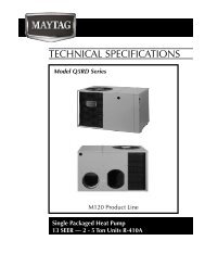
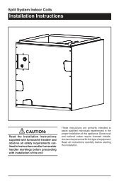
FURNACE SPECIFICATIONSUpflow *RC FurnacesCombustion AirInlet23 1/4"A ‡3/4"3/4"Exhaust Vent22 1/2"19 3/4"25 1/8"Combustion AirVent 3"C ‡ 2 1/4"(See Fig. 15 3/4" 3/4"for sizes)2" PVCExhaustVent(See Fig. 15for sizes)B ‡43"15"1 1/2" x 3 1/2" Dia.Opening forGas Connection7/8" Dia. ElectricConnection25 1/4"8"+20 1/2"33"27 5/8"+25 5/8"30 1/4"25 1/4"8"D ‡Return Air Opening(Bottom)1 1/2" x 3 1/2" Dia.Opening forGas Connection7/8" Dia. ElectricConnection1"1 1/4"23"Condensate Drain Outlets23"Side Return Bottom Return Opening28"‡ See Table 34Figure 1. Upflow Unit Dimensions
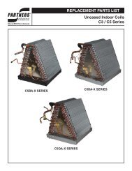
Downflow *RL Furnace3/4"3/4"Combustion Air Inlet24 1/2"Exhaust VentExhaust Vent2" Dia.22 1/2" 3/4"AB‡‡C‡C L24 7/8"43"7/8" Dia. ElectricConnection21 7/8"1 1/2" x 3 1/2" Dia.Opening forGas Connection21 1/4"15 1/2"21 1/2"8"1"27 7/8"CondensateDrain Outlet‡ See Table 3DBottom SupplyAir Opening3/4"2 1/2"21 1/2"CondensateDrain OutletCombustionVent(3" for 80/1002" for 40/60)19 3/4"24 7/8"7/8" Dia. ElectricConnection21 7/8"1 1/2" x 2 1/2"Knockout ForGas Connection10 1/4"19 3/4"Bottom Opening3/4"Figure 2. Downflow Unit Dimensions5
CAPACITIES —Furnace Airflow DataG6RC UPFLOW FURNACEModel Heating External Static Pressure (Inches Water Column)Number Input Motor Motor 0.1 0.2 0.3 0.4 0.5 0.6 0.7 0.8*RC- (Btuh) Speed HP CFM Rise CFM Rise CFM Rise CFM Rise CFM Rise CFM Rise CFM Rise CFM RiseHigh* 950 36 920 38 890 39 850 41 800 43 750 46 690 50 630 55040( )-08A 40,000 Medium** 1/5 740 47 710 49 680 51 650 53 600 58 550 63 490 - 430 -Low 620 56 590 59 560 62 520 - 470 - 410 - 350 - 290 -High* 1330 - 1280 - 1230 - 1170 - 1120 - 1030 - 940 37 850 41040( )-12A 40,000 Medium** 1/3 1190 - 1160 - 1110 - 1060 - 1010 - 910 38 820 42 720 48Low 830 42 810 43 780 44 760 46 720 48 670 52 610 57 550 63High* 1310 - 1260 - 1210 - 1160 45 1100 47 1040 50 980 53 920 56060( )-12A 60,000 Medium** 1/3 1160 45 1120 46 1080 48 1050 49 990 52 940 55 890 58 830 63Low 800 65 780 67 760 68 740 70 710 73 680 - 650 - 620 -High* 1775 38 1724 39 1652 40 1583 42 1505 44 1430 46 1343 49 1226 54080( )-12B 80,000 Med-High** 1/2 1417 47 1385 48 1339 50 1280 52 1224 54 1163 57 1097 61 1013 66Med-Low 1031 65 987 67 967 69 914 73 882 75 839 - 783 - 692 -Low 808 - 751 - 717 - 679 - 641 - 595 - 538 - 430 -High* 1840 - 1780 - 1700 41 1630 42 1550 45 1470 47 1380 50 1290 54080( )-16B 80,000 Med-High** 1/2 1600 43 1560 44 1470 47 1400 49 1350 51 1280 54 1210 57 1150 60Med-Low 1380 50 1350 51 1300 53 1250 55 1190 58 1120 62 1040 67 960 -Low 1100 63 1050 66 1000 69 950 - 900 - 850 - 800 - 750 -High* 2215 30 2155 31 2090 32 2030 33 1975 34 1885 35 1810 37 1730 39080( )-20B 80,000 Med-High 3/4 2000 33 1970 34 1930 35 1870 36 1820 37 1755 38 1695 39 1625 41Med-Low 1670 39 1665 40 1660 41 1630 41 1590 42 1535 43 1470 45 1410 47Low** 1365 48 1360 49 1350 49 1340 50 1305 51 1300 51 1255 53 1225 54High* 1910 45 1860 47 1780 49 1700 51 1620 53 1520 57 1420 61 1310 66100( )-16B 100,000 Med-High** 1/2 1640 53 1620 53 1540 56 1480 58 1420 61 1340 65 1250 69 1150 75Med-Low 1440 60 1410 61 1370 63 1320 66 1270 68 1210 72 1140 - 1060 -Low 1230 70 1210 72 1180 73 1140 - 1090 - 1030 - 960 - 880 -High* 2195 39 2140 40 2065 41 2000 42 1960 44 1860 46 1780 48 1695 50100( )-20B 100,000 Med-High** 3/4 1975 43 1910 44 1875 45 1845 46 1805 47 1735 50 1670 51 1590 53Med-Low 1650 51 1615 52 1605 53 1570 54 1540 55 1485 57 1435 59 1370 62Low 1320 64 1300 65 1280 66 1275 67 1265 67 1250 68 1210 70 1160 73High* 1860 56 1800 58 1730 60 1650 63 1570 66 1480 70 1380 75 1270 82120( )-16C 120,000 Med-High** 1/2 1650 63 1610 65 1550 67 1480 70 1410 74 1320 79 1230 84 1120 -Med-Low 1440 72 1410 74 1380 75 1320 79 1280 81 1220 85 1150 - 1080 -Low 1230 84 1210 - 1180 - 1140 - 1090 - 1030 - 960 - 880 -High* 2260 - 2200 - 2140 - 2070 - 1990 - 1910 - 1810 57 1710 61120( )-20C 120,000 Med-High** 3/4 1870 56 1840 56 1790 58 1760 59 1710 61 1660 63 1610 65 1560 67Med-Low 1540 67 1530 68 1510 69 1470 71 1430 73 1370 76 1300 80 1220 85Low 1360 76 1330 78 1310 79 1280 81 1250 83 1220 85 1190 - 1150 -Table 1. Furnace Airflow DataNOTES: 1. Airfl ow rates of 1800 CFM or more require two return air connections. Data is for operation with filter(s).2. Temperature rises in the table are approximate. Actual temperature rises may vary.3. Temperature rises and airfl ows for external static pressures greater than 0.5 are for reference only.These conditions are not recommended.( ) Can be C or N** Factory Set Cooling Speed** Factory Set Heating Speed- Not Recommended6
CAPACITIES —Furnace Airflow Data continuedModel Heating External Static Pressure (Inches Water Column)Number Input Motor Motor 0.1 0.2 0.3 0.4 0.5 0.6 0.7 0.8*RL- (Btuh) Speed HP CFM Rise CFM Rise CFM Rise CFM Rise CFM Rise CFM Rise CFM Rise CFM RiseHigh* 1280 - 1210 - 1180 - 1140 - 1090 - 1070 - 1030 - 990 -040()-12 40,000 Medium 1/3 1140 - 1090 - 1060 - 1030 - 980 35 950 36 910 37 870 39Low** 875 39 835 41 820 41 805 42 780 43 770 44 760 45 750 45High* 1260 40 1190 43 1155 44 1120 45 1075 47 1030 49 980 52 940 54060()-12 60,000 Medium** 1/3 1120 45 1070 48 1040 49 1010 50 960 53 930 55 890 57 850 60Low 855 59 815 62 800 64 780 65 760 67 730 70 710 - 690 -High* 1635 - 1585 - 1525 - 1460 46 1400 48 1330 51 1260 54 1180 57080()-16 80,000 Med-High** 1/2 1435 47 1395 49 1350 50 1300 52 1255 54 1200 56 1150 59 1090 62Med-Low 1230 55 1200 56 1165 58 1130 60 1090 62 1050 65 1000 68 960 71Low 1050 - 1035 - 1010 - 980 - 950 - 910 - 870 - 820 -High* 1600 53 1555 54 1500 56 1445 59 1380 61 1310 65 1240 68 1160 73100()-16 100,000 Med-High** 1/2 1475 57 1435 59 1385 61 1335 63 1290 66 1240 68 1190 71 1130 75Med-Low 1320 - 1290 - 1250 - 1215 - 1170 - 1120 - 1070 - 1020 -Low 1150 - 1130 - 1110 - 1075 - 1040 - 1000 - 950 - 890 -High* 2085 48 2035 49 1965 51 1910 52 1840 54 1780 56 1715 58 1630 61120()-20 100,000 Med-High** 3/4 1925 52 1885 53 1835 55 1780 56 1730 58 1675 60 1615 62 1540 65Med-Low 1720 58 1670 60 1630 61 1610 63 1570 64 1510 66 1465 68 1415 72Low 1500 66 1495 69 1460 66 1430 70 1400 72 1365 73 1315 - 1265 -( ) Can be C or N* Factory Set Cooling Speed** Factory Set Heating Speed- Not Recommended1. Airflow rates of 1800 CFM or more require two return air connections.Data is for operation with fi lter(s).2. Temperature rises in the table are approximate. Actual temperature rises may vary.3. Temperature rises and airfl ows for external static pressures greater than 0.5 are for reference only.These conditions are not recommended.Table 2. Furnace Airflow Data7
SAFETY INFORMATION1. Use only with type of gas approved for thisfurnace. Refer to the furnace rating plate.2. Install this furnace only in a location andposition as specifi ed on Table 4 of theseinstructions.3. Provide adequate combustion and ventilationair to the furnace space as specifi edon Pages 13 through 16.4. Provide adequate clearances around thevent air intake terminal(s) as specifi ed onFigures 18 through 23 of these instructions.5. Combustion products must be dischargedoutdoors. Connect this furnace to an approvedvent system only, as specifi ed onPages 16 through 26.6. Never test for gas leaks with an open fl ame.Use a commercially available soap solutionmade specifi cally for the detection of leaksto check all connections, as specifi ed onPage 28 of these instructions.7. Always install furnace to operate within thefurnace’s intended temperature-rise rangewith a duct system which has an externalstatic pressure within the allowable range,as specified on Table 2 of these instructions.See furnace rating plate.8. When a furnace is installed so that supplyducts carry air circulated by the furnaceto areas outside the space containing thefurnace, the return air shall also be handledby duct(s) sealed to the furnace casing andterminating outside the space containingthe furnace.9. A gas-fired furnace for installation in a residentialgarage must be installed as specifiedon Page 10 of these instructions.10. The furnace is not to be used for temporaryheating of buildings or structures underconstruction.INSTALLATION REQUIREMENTSRequirements and CodesThis furnace must be installed in accordance withthese instructions, all applicable local buildingcodes, and the current revision of the NationalFuel Gas Code (ANSI-Z223.1, NFPA-54). Thecurrent revision of the National Fuel Gas Codeis available from:American National Standards Institute, Inc.1430 BroadwayNew York, New York 10018Canada installations shall comply with CAN/CGA-B149 installation codes, local plumbing or wastewater codes and other applicable codes.Additional helpful publications are:• NFPA-90A - Installation of Air Conditioningand Ventilating Systems.• NFPA-90B - Warm Air Heating and AirConditioning Systems.These publications are available from:National Fire Protection Association, Inc.Batterymarch ParkQuincy, Massachusetts 02269WARNING:This furnace is not approved for installationin mobile homes. Installation in amobile home could cause fire, propertydamage, and/or personal injury.IMPORTANT NOTEThe Commonwealth of Massachusetts requirescompliance with regulation 248 CMR 4.00 and5.00 for installation of through – the – wall ventedgas appliances as follows:(a) For direct-vent appliances, mechanicalventheating appliances or domestic hotwater equipment, where the bottom of thevent terminal and the air intake is installedbelow four feet above grade the followingrequirements must be satisfi ed:1. If there is not one already present,on each fl oor level where there arebedroom(s), a carbon monoxide detectorand alarm shall be placed in the livingarea outside the bedroom(s). Thecarbon monoxide detector shall complywith NFPA 720 (2005 Edition).2. A carbon monoxide detector shall belocated in the room that houses the applianceor equipment and shall:a. Be powered by the same electricalcircuit as the appliance or equipmentsuch that only one service switch8
ModelNumberFurnaceBtuhDimensions (inches)A B C DTable 3. Furnace Dimensions and Shipping WeightsShippingWeight(lbs)*RC040 40,000 14 1/4 12 3/4 5 1/8 11 3/4 133*RC060 60,000 14 1/4 12 3/4 5 1/8 11 3/4 140*RC080 80,000 19 3/4 18 1/4 7 7/8 17 1/4 172*RC100 100,000 19 3/4 18 1/4 7 7/8 17 1/4 180*RC120 120,000 22 1/2 21 9 1/4 20 204*RL040 40,000 14 1/4 12 3/4 4 5/8 12 3/4 135*RL060 60,000 14 1/4 12 3/4 4 5/8 12 3/4 135*RL080 80,000 19 3/4 18 1/4 10 18 1/4 174*RL100 100,000 19 3/4 18 1/4 10 18 1/4 185*RL120 120,000 22 1/2 21 12 1/2 21 1/8 209CLEARANCES TO COMBUSTIBLE MATERIALSThis furnace is Designed Certified by CSA International for the minimum clearances to combustiblematerial listed in Table 4. See the furnace name plate, located inside the furnace cabinet, forspecifi c model number and clearance information.MINIMUM CLEARANCES TO COMBUSTIBLE MATERIALFurnace Cabinet Minimum Clearances (Inches)Input Width(Btuh) (Inches) Side Vent Back Top Front40,000 14 1/4 0 0 0 1 1*60,000 14 1/4 0 0 0 1 1*80,000 14 1/4 0 0 0 1 1*100,000 19 3/4 0 0 0 1 1*120,000 22 1/2 0 0 0 1 1** When installed horizontally, 24 inches is required for servicing.Table 4. Minimum Clearances to Combustible Materialsservices both the appliance and thecarbon monoxide detector;b. Have battery back-up power;c. Meet ANSI/UL 2034 Standardsand comply with NFPA 720 (2005Edition);andd. Have been approved and listed bya Nationally Recognized TestingLaboratory as recognized under 527CMR.3. A Product-approved vent terminal mustbe used, and if applicable, a Productapprovedair intake must be used. Installationshall be in strict compliancewith the manufacturer’s instructions. Acopy of the installation instructions shallremain with the appliance or equipmentat the completion of the installation.4. A metal or plastic identifi cation plateshall be mounted at the exterior of thebuilding, four feet directly above the locationof vent terminal. The plate shallbe of suffi cient size to be easily readfrom a distance of eight feet away, andread “Gas Vent Directly Below”.9
(b) For direct-vent appliances, mechanicalventheating appliances or domestic hotwater equipment where the bottom of thevent terminal and the air intake is installedabove four feet above grade the followingrequirements must be satisfied:1. If there is not one already present,on each fl oor level where there arebedroom(s), a carbon monoxide detectorand alarm shall be placed in the livingarea outside the bedroom(s). Thecarbon monoxide detector shall complywith NFPA 720 (2005 Edition).2. A carbon monoxide detector shall:a. Be located in the room that housesthe appliance or equipment;b. Be either hard-wired or battery poweredor both; andc. Shall comply with NFPA 720 (2005Edition).3. A Product-approved vent terminal mustbe used, and if applicable, a Productapprovedair intake must be used. Installationshall be in strict compliancewith the manufacturer’s instructions. Acopy of the installation instructions shallremain with the appliance or equipmentat the completion of the installation.LocationThe furnace must be installed on a level surface,and as close to the center of the air distributionsystem as possible. See Table 3 for overall dimensionsto determine the required clearancesin hallways, doorways, stairs, etc. to allow thefurnace to be moved to the installation point. Thefurnace must be installed so that all electricalcomponents are protected from water.Minimum clearances to combustible materialsare listed in Table 4. Access for positioning andservicing must be considered when locating theunit. Twenty four inches is the minimum requiredclearance for servicing the unit. Thirty inches isthe minimum required clearance for positioningthe unit. Thirty six inches is the recommendedclearance from the front of the unit. Please notethat a panel or door can be located such that theminimum clearance on the rating plate is satisfied, but that panel or door must be removableand allow the appropriate clearance for yourinstallation.This furnace is certifi ed for use on wood fl ooring.The furnace must be installed on a solid surfaceand must be level front to back and side to side.This furnace must not be installed directly oncarpeting, tile, or any combustible material otherthan wood fl ooring.DOWNFLOW WARNING(*RL Models):The design of the downfl ow furnace is certifiedfor natural or propane gas and for installation onnon-combustible fl ooring. A special combustiblefl oor sub-base is required when installing on acombustible fl oor. Failure to install the sub-basemay result in fire, property damage and personalinjury. The special downfl ow sub-bases are factorysupplied accessories, part number 902974,902677, 904108 and 904165. Part #904108 isan adjustable sub-base kit and it can be used onall cabinet sizes. When the furnace is installedon a factory or site-built cased air conditioningcoil, the sub-base is not necessary. However,the plenum attached to the coil casing must beinstalled such that its surfaces are at least 1”from combustible construction.A gas-fi red furnace installed in a residential garagemust be installed so that the burners and theignition source are located a minimum of 18” fromthe floor. The furnace must be located or protectedto avoid physical damage by vehicles.HORIZONTAL INSTALLATIONSThe upfl ow model furnaces are approved forhorizontal installation. Installation Kit #903568is available for horizontal applications. Theparts may also be fi eld supplied. NOTE: Downflow models are NOT approved for horizontalinstallation.CAUTION:Damage to the product resultingfrom failure to follow instructions oruse of unauthorized parts may voidthe manufacturer’s product warrantycoverage.The 90+ upfl ow furnace can be installed horizontallyin an attic, basement, crawl space oralcove. This furnace can be installed horizontallyto the clearances listed in Table 4 on a platform10
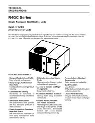
5/8" Vinyl Cap 1/4" Vinyl CapGreyTubing3" to 2"Reducer(Optional)PVC TeePVC ReducerBushingPressure SwitchDrain Trap1/2" VinylCap SoftTubingSoft TubingLooped to Providea Drain TrapFigure 3. 90+ Upflow Converted for Horizontal Installation (Horizontal Right)AlternativeforHorizontalVentPVC Tee3" to 2"Reducer(Optional)Drainage Portis DownardPressure Switch(Condensate)Soft TubingVinyl CapPressureSwitchReducerBushingSoft TubingLooped to Providea Drain TrapSoftTubingGreyTubing Drain Trap1/4" Vinyl CapFigure 4. 90+ Upflow Converted for Horizontal Installation (Horizontal Left)or on the ceiling rafters. Note that the platformand the ceiling rafters must be able to supportthe weight of the furnace being installed. It canalso be suspended from a ceiling in a basementor utility room in either a right to left airfl ow orleft to right airflow.When installed horizontally, the furnace mustbe raised above the surface to allow a draintrap to hang vertically below the furnace. Thiswill allow for proper drainage of the condensatefrom the furnace.Conversion of the 90+ Upflow Furnace for aHorizontal Right Installation.1. Remove the hard “J” tube drain trap assembly.2. Place the 5/8” cap plug over the draintap in the header box from which the “J”drain trap assembly was removed.3. Remove the piece of soft tubing runningfrom the in-line drain assembly to theheader box and place a 1/2” vinyl capover the drain tap in the in-line drainassembly.4. Remove the grey tubing from the pressureswitch to the header box. Removethe 1/4” cap from the pressure tap on theright side of the header box and place iton the corresponding pressure tap on theopposite side of the header box.Conversion of the 90+ Upflow Furnace for aHorizontal Left Installation.Refer to Figure 4 for details and descriptionof parts required for the horizontal left conversion.1. Remove the hard “J” tube drain trap assembly.2. Ensure that the piece of soft tubing runningfrom the in-line drain assembly tothe header box is in place with the drainoriented downwards (See Figure 4).3. Connect a draw trap to the right side ofthe header on the furnace. The draintrap must be installed according to localcode. NOTE: A downward slope mustbe maintained on the tube as it is routedthrough the furnace (when the furnaceis in the horizontal position).11
NOTE: To avoid condensate freezing in the draintrap assembly and tubing, insulate aroundthe drain trap assembly and all tubing locatedin unconditioned space.NOTE: When converting the furnace, to horizontalleft, ensure that the drainage port on the in-linedrain assembly is downward as shown in Figure4. If the in-line drain assembly is not rotated, thenthe furnace may not drain properly.SUPPLY AIR PLENUM INSTALLATIONA. Installation on a concrete slab - *RL1. Construct a hole in the fl oor per thedimensions in Figure 5.2. Place the plenum and the furnace asshown in Figure 6.B. Installation on a combustible floor - *RL1. Cut hole and frame the hole per thedimensions in Figure 7.2. Place sub-base for combustible fl oorsover the hole with its duct collar extendeddownward. Attach the supply air plenumto the base in a manner which will assure1” clearance to the flooring or othercombustible material. Place furnaceon the combutsible base as shown inFigure 8.3. When the furnace is installed on a factoryor site-built cased air conditioningcoil, the sub-base is not necessary.However, the plenum attached to thecoil casing must be installed such that itssurfaces are at least 1” from combustiblematerial in Figure 9.CIRCULATING AIR SUPPLYPlenums and air ducts must be installed in accordancewith the Standard for the Installation ofAir Conditioning and Ventilating Systems (NFPANo. 90A) or the Standard for the Installation ofWarm Air Heating and Air Conditioning Systems(NFPA No. 90B).If outside air is utilized as return air to the furnacefor ventilation or to improve indoor air quality, thesystem must be designed so that the return air tothe furnace is not less than 50°F (10°C) duringheating operation. If a combination of indoor andoutdoor air is used, the ducts and damper systemmust be designed so that the return air supply tothe furnace is equal to the return air supply undernormal, indoor return air applications.When a cooling system is installed which uses thefurnace blower to provide airfl ow over the indoorcoil, the coil must be installed downstream (on theoutlet side) or in parallel with the furnace.If a cooling system is installed in parallel with thefurnace, a damper must be installed to preventchilled air from entering the furnace and condensingon the heat exchanger. If a manually operateddamper is installed, it must be designed so thatoperation of the furnace is prevented when thedamper is in the cooling position and operationof the cooling system is prevented when thedamper is in the heating position.WARNING:Products of combustion must not beallowed to enter the return air ductworkor the circulating air supply. Failureto prevent products of combustionfrom being circulated into the livingspace can create potentially hazardousconditions including carbon monoxidepoisoning that could result in personalinjury or death.All return ductwork must be securedto the furnace with sheet metal screws.For installations in confined spaces,all return ductwork must be adequatelysealed and joints must be taped. Whenreturn air is provided through the bottomof the furnace, the joint betweenthe furnace and the return air plenummust be sealed.The floor or platform on which the furnaceis mounted must provide soundphysical support of the furnace with nogaps, cracks, or sagging between thefurnace and the floor or platform.Return air and circulating air ductworkmust not be connected to any otherheat producing device such as a fireplaceinsert, stove, etc.12
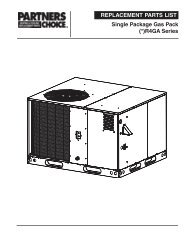
Return AirThe return air ductwork may be connected to anyor all of the following: left side return, right sidereturn, or bottom return. Tables 1 and 2 showthe airfl ow data for each furnace model. Wheremaximum airflow is 1800 CFM or more twoopenings must be used.VENTING AND COMBUSTION AIRREQUIREMENTSNORDYNE condensing furnaces may be installedwith outdoor combustion air piped directly to thefurnace, or without such special piping. Codesrefer to the former as “direct vent” or “two pipe”installation. Installation with air taken from aroundthe furnace is sometimes referred to as “onepipe” installation where only the vent (exhaust)pipe is provided.Provisions must be made for adequate supplyof air for combustion and ventilation. ForUnited States installations, the adequacy of airprovisions can be determined by consulting thecurrent version of the National Fuel Gas Code(ANSI Z223.1/NPFA-54). For Canadian installations,requirements are specifi ed in the NationalStandard of Canada (CAN/CGA B149.1 & .2).Consult local codes for special requirements.An important consideration in selecting one ortwo pipe installation is the quality of the combustionair. Indoor air is sometimes contaminatedwith various household chemicals which cancause severe corrosion in the furnace combustionsystem.NOTE: If the furnace is operated without adequateair for combustion and ventilation, it may notperform properly. Furnace components may bestrained by high temperature and could fail .WARNING:Furnace installation using methodsother than those described in the followingsections must comply with theNational Fuel Gas Code and all applicablelocal codes to provide sufficientcombustion air for the furnace.ConcreteFloorFurnaceSheetMetalPlenumFigure 6. Furnace on a Concrete SlabABABMODEL A B*RL 040/060 13.25” 19.25”*RL 080/100 18.75” 19.25”*RL 120 21.50” 19.25”MODEL A B*RL 040/060 13.25” 19.63”*RL 080/100 18.75” 19.63”*RL 120 21.50” 19.63”Figure 5. Opening for Concrete SlabFigure 7. Opening in Wood Floor13
DownflowSub-baseFurnaceWoodFloorSheetMetalPlenumUpflow ModelsProtectiveScreenDownflow ModelsFigure 8. Furnace on a Wood Floor18.75"or 13.25" or 21.50"** RL 040/060** RL 120Figure 10. Protective Screen forOne Pipe Installations9.25"2.0"Vent orChimneyEach opening mustbe at least 100 sq. in.or 1 sq. in. per 1000Btuh of total inputrating, whichever isgreater. See minimumarea per table.16.75"or 11.25"1.50"19.75"or 14.25"*or 22.50"**28.38"1.58"1 inch thick fiberglass 3 lb density3"19.63"Total InputRating (Btuh)40,00060,00080,000100,000120,000140,000160,000Water HeaterFurnaceMinimumFree Area(Each Opening)100 sq. in.100 sq. in.100 sq. in.100 sq. in.120 sq. in.140 sq. in.160 sq. in.12" Max.12" Max.Round DuctDiameter12"12"12"12"13"14"15"Figure 9. Downflow Sub-BaseDimensionsFigure 11. Equipment in a Confined Spacewith all Combustion Air drawn from Inside14
----Each openingto outside mustbe at least1 sq. in. per4000 Btuh oftotal inputrating.--12"MaxVent orChimneyFurnaceFurnaceAlternateAir InletVent orChimneyOutletAirWaterHeaterInlet AirVentilation Louvers(each end of attic)NOTE: Air openingsshall eachhave a free areaof not less thanone square inchper 4,000 Btuh ofthe total input ratingof all equipmentin the enclosure.12" MaxWater HeaterTotal InputRating (Btuh)40,00060,00080,000100,000120,000140,000160,000MinimumFree Area(Each Opening)10 sq. in.15 sq. in.20 sq. in.25 sq. in.30 sq. in.35 sq. in.40 sq. in.Round DuctDiameter4"5"5"6"6"7"8"Figure 12. Equipment in a Confined Spacewith all Combustion Air drawn from Outdoorsthrough Exterior WallVentilation Louvers ForUnheated Crawl SpaceFigure 14. Equipment in a Confined Spacewith all Combustion Air drawn from Outdoorsthrough Ventilated Crawl Space andVentilated AtticVentilation Louvers at each end of atticVent orChimneyAtticInsulationTotal InputRating (Btuh)40,00060,00080,000100,000120,000140,000160,000FurnaceWater HeaterMinimumFree Area(Each Opening)10 sq. in.15 sq. in.20 sq. in.25 sq. in.30 sq. in.35 sq. in.40 sq. in.Air Duct must beat least 1 sq. in.per 4,000 Btuh oftotal input rating.Ducts mustextend aboveattic insulation.Air Duct must beat least 1 sq. in.per 4,000 Btuh oftotal input rating.12" MaxRound DuctDiameter4"5"5"6"6"7"8"Vent orChimneyTotal InputRating (Btuh)40,00060,00080,000100,000120,000140,000160,000FurnaceWater HeaterMinimumFree Area(Each Opening)20 sq. in.30 sq. in.40 sq. in.50 sq. in.60 sq. in.70 sq. in.80 sq. in.Air DuctAir DuctAir Ductmust beat least1 sq. in.per 2000Btuh oftotal inputrating.Round DuctDiameter5"6"7"8"9"10"10"Figure 13. Equipment in a ConfinedSpace with all Combustion Air drawn fromOutdoors through Vertical Ducts – fromVentilated AtticFigure 15. Equipment in a Confined Spacewith all Combustion Air Drawn from theOutside through Horizontal Ducts15
Combustion Air QualityThe recommended source of combustion air isto use the outdoor air supply. However, the useof indoor air in most applications is acceptableexcept as follows:1. If the furnace is installed in a confi nedspace it is recommended that the necessarycombustion air come from the outdoors byway of attic, crawl space, air duct, or directopening.2. If outdoor combustion air is used, theremust be no exposure to the installations orsubstances listed in Item 3 below.3. The following types of installation may requireOutdoor Air for combustion, due tochemical exposures:• Commercial buildings• Buildings with indoor pools• Furnaces installed in laundry rooms• Furnaces installed in hobby or craftrooms• Furnaces installed near chemical storageareasExposure to the following substances inthe combustion air supply may also requireOutdoor Air for combustion:• Permanent wave solutions• Chlorinated waxes and cleaners• Chlorine based swimming pool chemicals• Water softening chemicals• De-icing salts or chemicals• Carbon tetrachloride• Halogen type refrigerants• Cleaning solvents (such as perchloroethylene)• Printing inks, paint removers, varnishes,etc.• Hydrochloric acid• Cements and glues• Antistatic fabric softeners for clothes dryers• Masonry acid washing materialsAir Requirements For One-PipeInstallationWhen air for combustion is to be taken fromaround the furnace, a protective screen must beinstalled over the combustion air intake opening.This screen is provided with the furnace installationinstructions and functions to prevent debrisfrom entering the combustion system. It shouldbe installed on the combustion air intake collaror inlet PVC. If furnace location is such that thisopening might be unintentionally obstructed, a 3”PVC elbow must be installed on the collar, andthe screen placed inside the inlet of the elbow.See Figure 10.Installation In An UnconfinedSpaceCAUTION:“Tight” buildings (with weather strippingand caulk to reduce infiltration),may require special provisions forintroduction of outside air to ensuresatisfactory combustion and venting,even though the furnace is located inan unconfined space.An unconfi ned space is an area including allrooms not separated by doors with a volumegreater than 50 cubic feet per 1,000 Btuh of thecombined input rates of all appliances whichdraw combustion air from that space. For example,a space including a water heater ratedat 45,000 Btuh and a furnace rated at 75,000Btuh requires a volume of 6,000 cubic feet [50 x(45 + 75) = 6,000] to be considered unconfi ned.If the space has an 8 foot ceiling, the fl oor areaof the space must be 750 square feet (6,000/ 8 = 750). In general, a furnace installed in anunconfi ned space will not require outside air forcombustion.WARNING:Furnaces installed with combustionair drawn from a heated space whichincludes exhaust fans, fireplaces, orother devices that may produce a negativepressure should be consideredconfined space installations.Installation In A Confined SpaceA confi ned space is one which does not meetthe unconfi ned space volume requirements, andtypically involves installation in a small room. Allsuch installations must have specifi c provisionsfor introduction of combustion and ventilation air.Codes require that two openings be provided forthis - one with bottom edge within 12” of the fl oorand one with top edge within 12” of the ceiling.16
The size and other criteria for these openingsmust be per the following sections.Combustion air openings must not be restrictedin any manner.Furnaces installed in a confi ned space whichsupply circulating air to areas outside of thespace must draw return air from outside thespace and must have return air ducts tightlysealed to the furnace.Air From InsideAir for combustion and ventilation may be takenfrom inside the building through an interior wall ifthe building is not “tight” and if the total volumeof the furnace space and the space from whichair is drawn meets the volume requirements foran unconfi ned space. In such cases, the twoopenings in the wall must each have free area ofat least one square inch per 1000 Btuh of totalappliance input, but not less than 100 squareinches of free area. See Figure 11. For example,if the combined input rate of all appliances is lessthan or equal to 100,000 Btuh, each opening musthave a free area of at least 100 square inches.If the combined input rate of all appliances is120,000 Btuh, each opening must have a freearea of at least 120 square inches.Air Directly Through An Exterior WallIf combustion air is provided directly through anexterior wall, the two openings must each havefree area of at least one square inch per 4000Btuh of total appliance input. (See Figure 12.)Outdoor Air Through Vertical Openings orDuctsIf combustion air is provided through vertical ductsor openings to attics or crawl spaces, the twoopenings must each have free area of at leastone square inch per 4000 Btuh of total applianceinput. Ducts must have cross-sectional areas atleast as large as the free area of their respectiveopenings to the furnace space. Attics or crawlspaces must communicate freely with the outdoorsif they are the source of air for combustionand ventilation. (See Figures 13 and 14.)Outdoor Air Through HorizontalOpenings or DuctsIf combustion air is taken from outdoors throughhorizontal ducts, the openings must each havefree area of at least one square inch per 2000Btuh of total appliance input. Ducts must havecross-sectional area at least as large as the freearea of their respective openings to the furnacespace. (See Figure 15.)CAUTION:Do not supply combustion air from anattic space that is equipped with powerventilation or any other device that mayproduce a negative pressure.VENTING REQUIREMENTSThis section specifi es installation requirementsfor vent and “2-pipe” combustion air piping. For“one pipe” installations, install vent piping perthis section and provide air for combustion andventilation per the previous section. The capacitytable provided in this section applies to the totalof vent and combustion air piping for either typeof installation.NORDYNE condensing furnaces are classified as“Category IV” appliances, which require specialventing materials and installation procedures.Category IV appliances operate with positivevent pressure and therefore require vent systemswhich are thoroughly sealed. They also producecombustion condensate, which is slightly acidicand can cause severe corrosion of ordinary ventingmaterials. Furnace operation can be adverselyaffected by restrictive vent and combustion airpiping. Therefore, vent and combustion air pipinglengths must conform completely to the requirementsof Table 5.The furnace must be vented to the outdoors. Itmust not be vented in common with any otherappliance, even if that appliance is of the condensingtype. Common venting can result in severecorrosion of other appliances or their venting andcan allow combustion gases to escape throughsuch appliances or vents. Do not vent the furnaceto a fi replace chimney or building chase.WARNING:FURNACE MUST NOT BE COMMONVENTED WITH OTHER APPLIANCES.Horizontal InstallationsIn order to ensure complete drainage of allcondensate, an additional “T” drain assemblymay be installed in line with the vent piping (seeFigures 3 & 4). The “T” assembly may consistof a 2” PVC tee with a 2’ to 1/2” PVC reducerbushing , and a barb fi tting. These parts areavailable in Horizontal Vent Kit 903568, or theycan be fi eld supplied.17
WARNING:CARBON MONOXIDEPOISONING HAZARD1. Seal any unused openings in the ventingsystem2. Inspect the venting system for propersize and horizontal pitch, as requiredin the National Fuel Gas Code, ANSIZ223.1 or the CAN/CGA B149 InstallationCodes and these instructions.Determine that there is no blockageor restriction, leakage, corrosion andother deficiencies which could causean unsafe condition.3. So far as is practical, close all buildingdoors and windows and all doorsbetween the space in which theappliance(s) connected to the ventingsystem are located and other spacesof the building.4. Follow the lighting instructions. Placethe appliance being inspected in operation.Adjust thermostat so applianceshall operate continuously.5. Turn on clothes dryers and any otherappliance not connected to the ventingsystem. Turn on any exhaust fans,such as range hoods and bathroomexhausts, so they shall operate at maximumspeed. Do not operate a summerexhaust fan.6. Close fireplace dampers.7. Test for spillage from draft hoodequipped appliance at the draft hoodrelief opening after 5 minutes of mainburner operation. Use the flame of amatch or candle.8. If improper venting is observed duringany of the above tests, the venting systemmust be corrected in accordancewith the National Fuel Gas Code, ANSIZ223.1/NFPA 54 and/or CSA B149.1,Natural Gas and Propane InstallationCodes.9. After it has been determined that eachappliance connected to the ventingsystem properly vents when tested asoutlined above, return doors, windows,exhaust fans, fireplace dampers andany other gas burning appliance totheir previous conditions of use.Vent Pipe MaterialVent and combustion air pipe and fittings must beone of the following materials and must conformto the indicated ANSI/ASTM standards:MaterialStandardSchedule 40 PVC D1785PVC-DWVD2665SDR-21D2241& SDR-26ABS-DWVD2661Schedule 40 ABS F628Foam/Cellular Core PVC F891*In Canada, all plastic vent pipe must be certifiedto ULC S636.Cement and primer must conform to ATSMStandard D2564 for PVC and Standard D2235for ABS. When joining PVC piping to ABS, usePVC solvent cement. (See procedure specifi edin ASTM Standard D3138.)Vent Pipe Length and DiameterIn order for the furnace to operate properly,the combustion air and vent piping must not beexcessively restrictive. To ensure this use Table5, which indicates the maximum allowable pipinglength for a furnace of specifi ed input rate,when installed with piping of selected diameterand number of elbows. This table applies to thelength and number of elbows for each pipe. Touse the table, the furnace input rate, the centerlinelength and the number of elbows on eachpipe must be known. Choose the diameter forwhich the tabulated length is equal to or greaterthan required.Proper use of the table is illustrated by the followingexample:Example:An 80,000 Btu/h furnace is to be installed in a“one-pipe” system with 40 feet of vent piping.There are a total of four long radius 90-degreeelbows used in the vent, including the one exteriorto the building.Solution:For this particular installation, the equivalent ventlength must be calculated. This equivalent ventlength will then be compared to the maximumallowable vent length given in Table 5. Then, thediameter of the piping can be chosen for which theequivalent vent length is less than the maximum18
APPLICATIONSINGLE PIPE LENGTH (ft.)with 1 long radius elbow*DIRECT VENT, DUAL PIPE LENGTH (ft.)with 1 long radius elbow on each pipe*PVC,CPVC or ABS Outlet Outlet Inlet/Outlet Inlet/Outlet Inlet/OutletSCH. 40 Pipe Size 2” 3” 2” 2” 3” 2” 3” 3”Models 040 80 150 40 40 50 50 90 90Models 060 & 080 60 150 30 30 35 35 90 90Models 100 & 120 30 150 15 15 25 25 90 90**NOTES1. Subtract 2.5 ft. for each additional 2” long radius elbow, 5 ft. for each additional 2” short radius elbow, 3.5’for each additional 3” long radius elbow, and 7’ for each additional 3” short radius elbow.2. Two 45 degree elbows are equivalent to one 90 degree elbow.3. Do not include termination elbows in calculation of vent length4. This table is applicable for elevations from sea level to 2000 ft. For higher elevations decrease vent pipelengths by 8% per 1000 ft. of altitude.5. Only the above pipe materials are approved for use with these condensing furnaces.Table 5. Vent TableUpflow Furnaces5/8"InletExhaustSee Vent Table 5Straps or Other SuitableSupports at Minimum of 5 ft. IntervalsSeal/Caulkaround Pipeat BuildingCombustion90˚ ElbowOffset withExhaust Pipefor AdequateDimensionalClearancePVC orABS PipeUpward Pitch - 1/4" per FootOutlet Exhaust VentFirst Support Placedas Close to Furnace WallConnection as PossibleExhaust Vent7"12" Min.Normal Snow LevelStraight Neoprene Couplingwith 2 Hose Clamps*(Optional - Not Shown)Downflow FurnacesSeal/Caulkaround Pipeat BuildingSee Vent Table 5Straps or Other SuitableSupports at Minimum of 5 ft. IntervalsExhaustInlet5/8"90˚ Elbow12" Min.Normal Snow LevelUpward Pitch - 1/4" per FootOutlet Exhaust VentFirst Support PlacedWall as Close to FurnaceConnection as PossibleExhaust VentCombustion AirInletOffset with ExhaustPipe for AdequateDimensionalClearancePVC orABS PipeStraight NeopreneCoupling with2 Hose Clamps** These neoprene couplings are fi eld-supplied and can be used if the installation requires breakable connections in the piping.Note that a maximum of two couplings per pipe are allowed.Figure 16. Horizontal Venting19
allowable vent length. Returning to our example,we consult Table 5 and determine that for an80,000 Btu/h furnace the maximum vent lengthfor 2” diameter piping is 60 feet or for 3” diameterpiping is 150 feet. Note that the maximum ventlength given in Table 5 includes one long radiuselbow. Therefore, for our example, we have threeadditional long radius elbows for which we mustadd to our piping. Each long radius elbow isequivalent to 2.5 feet, so we must add 7.5 feetto our vent length. Therefore, the equivalent ventlength for our installation is 47.5 feet. We comparethis with the maximum vent length for 2” and 3”diameter piping. For both cases, our equivalentvent length is less than the maximum allowablevent length, so for our “one-pipe” installation wecan use either 2” or 3” diameter piping.Condensing furnace combustion products havevery little buoyancy, so Table 5 is to be usedwithout consideration of any vertical rise in thepiping.NOTE: Always use the same or larger sizepiping for combustion air as is used for theexhaust vent.Vent Pipe InstallationPipe Routing and SupportRoute piping as directly as possible betweenthe furnace and the outdoors and rememberthat routing affects pipe size requirements perthe preceding section. If a two pipe system isused, locate the combustion air intake and thevent exhaust in the same atmospheric pressurezone - i.e. both must exit the building though thesame portion of exterior wall or roof (See Figure22). Vent piping must be sloped upwards notless than 1/4” per foot in the direction from thefurnace to the terminal. This is to ensure thatany condensate flows back to the furnace (whereit can be disposed of through the condensatedisposal system).The quality of outdoor air must also be considered.Be sure that the combustion air intake isnot located near a source of solvent fumes orother chemicals which can cause corrosion ofthe furnace combustion system.CAUTION:Combustion air must not be drawnfrom a corrosive atmosphere.Piping must be mechanically supported so thatits weight does not bear on the furnace. Supportsmust be at intervals no greater than fi vefeet, and at smaller intervals if necessary toensure that there are no sagging sections totrap water. (See Figure 16.) It is recommendedto install couplings along the vent pipe, on eitherside of the exterior wall. These couplings maybe required by local code.Figure 18 illustrates vent and combustion air pipesizes exiting the furnace. Transition to the correctpipe size must be done close to the furnace sothat the full length of pipe is of proper size.Straight neoprene couplings are supplied withthe downfl ow furnaces only. These couplingsare to be installed in the combustion air inlet (ifpresent) and exhaust vent piping at the furnaceas shown in Figures 16. For an upfl ow furnaceinstallation, if breakable connections are requiredin the combustion air inlet (if present) and exhaustvent piping, then straight neoprene couplings for2” or 3” piping with hose clamps can be used.These couplings can be ordered through yourlocal furnace distributor.To install a coupling, slide the rubber couplingover the end of the pipe that is attached to thefurnace and secure it with one of the hose clamps.Then slide the other end of the rubber couplingonto the other pipe from the vent and secure thecoupling with the second hose clamp. Ensure thatthe connection is tight and leak free.NORDYNE condensing furnaces have been certified for installation with zero clearance betweenvent piping and combustible surfaces. However,it is good practice to allow space for conveniencein installation and service.Location of Outdoor TerminationsHorizontal VentingVent and combustion air intake terminationsmust be as shown in Figure 19 and 20. Venttermination clearances shall be consistent withthe National Fuel Gas Code, ANSI 2223.1/NFPA54 and/or the CSA B149.1, Natural Gas andPropane Installation Code.All minimum clearances specifi ed must bemaintained to protect building materials fromdegradation by fl ue gases.20
Upflow FurnacesSupport System onVertical Rise Below JointsSupport System withfirst support as closeto furnace as Possible5'CombustionAir PipeExhaustVentStraight NeopreneCouplings with2 Hose Clamps*(Optional - NotShown)Upward Pitch1/4" per FootCabinetFurnace FrontDownflow FurnacesSupport System onVertical Rise Below JointsSupport System withfirst support as closeto furnace as Possible5'ExhaustVentCombustionAir PipeStraight NeopreneRubber Couplingswith 2 Hose Clamps*Upward Pitch1/4" per FootCabinetFurnace FrontFigure 17. Vertical Venting* These couplings are fi eld-supplied and can be used if the installation requires breakable connectionsin the piping. Note that a maximum of two couplings per pipe are allowed.Upflow FurnacesCombustion Air Inlet Pipe CollarDiameter 3" for coupling or reducerFurnace Top2" PVC Exhaust Vent All ModelsDownflow FurnacesCombustion Air Inlet2" PVC on 040/060 models,3" PVC on 080/100 modelsFurnace Top2" PVCExhaust VentAll ModelsFigure 18. Furnace Pipe Adaptions21
WARNING:Ensure that the combustion air ventand the exhaust vent are configured asshown in Figure 19 and 20. Impropervent termination can cause recirculationof the flue gases. This mayresult in furnace vibration. In severecases, the furnace will cycle due tothe intermittent contact between theflame and the flame sensor. If younote oscillations occurring, check thevent configuration. Make sure thatthe exhaust vent does not have a 90degree termination.Vent and combustion air intake terminations mustbe located to ensure proper furnace operationand to conform to applicable codes. Figure 19and 20 illustrates necessary distances from thevent termination to windows and building air intakes.In Canada, the Canadian Fuel Gas Codetakes precedence over these instructions.Specifically, all minimum distance requirementswith respect to termination of the ventpiping listed below (items 1 through 8).The following list is a summary of vent terminallocation requirements:1. The termination must be 12 inches abovesnow level or grade level whichever ishigher. See Figure 18 for alternate methodto achieve 12” above snow level.2. The minimum distance for a (1-pipe installation)from any door, (openable) window, orgravity air inlet is 4 ft. below, 4 ft. horizontally,or 1 ft. above.3. The minimum distance for a direct vent (2-pipe) installation from any door, (openable)window, or air gravity inlet is 1 ft. below, 1ft. horizontally, or 1 ft. above.4. For one-pipe installations the recommendedminimum distance from an inside cornerformed by two exterior walls is 6 feet, butis not required.5. The vent termination for a 1-pipe installationshall be a minimum of 3 ft. above any forcedair inlet within 10 ft.6. The vent termination shall be located at least3 ft. horizontally from any electric meter, gasmeter, regulator and any relief equipmentin accordance to ANSI 2223.1/NFPA S4.These distances apply ONLY to U.S. installations.In Canada, the Canadian Fuel GasCode takes precedence.7. Avoid areas where condensate drainagemay cause problems by dropping on plantersor patios, etc. Also ensure that exhaustgases will not impinge on windows or buildingsurfaces, which may be compromised ordamaged by condensation. Do not install thevent terminal such that exhaust is directedinto window wells, stairwells, under decksor into alcoves or similar recessed areas,and do not terminate above any publicwalkways.8. Select the point of wall penetration wherethe minimum 1/4 inch per foot of slope upcan be maintained.CAUTION:For optimum performance, vent furnacethrough wall which experiencesthe least exposure to winter winds.For Canadian installations please refer to theCanadian Installation Code (CAN/CGA-B149.1or 2) and/or local codes.The horizontal venting kits consist of two faceplates and an insulating gasket to seal the exteriorsurface. A hole sized closely to the pipe diametermust fi rst be cut through the wall. A short lengthof pipe is then cut such that it can penetratethe wall and be held in place by closely fi ttingstandard couplings. The face plates are retainedon both sides of the wall by the couplings, andthe gasket is retained against the wall by theouter face plate. Face plates must be fastenedto the wall and the outside one must be fl ashedas appropriate to prevent entry of water.When the horizontal kits are not used, the followingsteps are required:1. Check the hole size cut through the exteriorwall. Insure that the hole diameter is lessthan the diameter of the couplings to beused.2. Extend the vent pipe through the wall approximately1” and seal the area betweenthe wall and pipe.3. If required by local code, apply couplingsto the vent pipe on the interior and exteriorsides of the wall to insure the pipe can notbe pushed or pulled through the wall.22
VENT TERMINAL AIR SUPPLY INLET AREA WHERE TERMINAL IS NOT PERMITTEDA = Clearance above grade, veranda, porch,deck, or balconyB = Clearance to window or door that may beopenedCanadian Installations 1 US Installations 212 inches (30 cm) 12 inches (30 cm)6 inches (15 cm) for appliances 10,000Btuh (3 kW), 12 inches (30 cm) forappliances > 10,000 Btuh (3 kW) and100,00 Btuh (30 kW), 36 inches (91 cm)for appliances >100,00 Btuh (30 kW)6 inches (15 cm) for appliances 10,000Btuh (3 kW), 9 inches (23 cm) forappliances > 10,000 Btuh (3 kW) and50,000 Btuh (15 kW), 12 inches (30 cm)for appliances > 50,000 Btuh (15 kW)C = Clearance to permanently closed window * *D = Vertical clearance to ventilated soffitlocated above the terminal within ahorizontal distance of 2 feet (61 cm) fromthe center line of the terminal* *E = Clearance to unventilated soffit * *F = Clearance to outside corner * *G = Clearance to inside corner * *H = Clearance to each side of center lineextended above meter/regulator assembly3 feet (91 cm) within a height 15 feetabove the meter/regulator assemblyI = Clearance to service regulator vent outlet 3 feet (1.83 m) *J = Clearance to nonmechanical air supply inletto building or the combustion air inlet to anyother appliance6 inches (15 cm) for appliances 10,000Btuh (3 kW), 12 inches (30 cm) forappliances > 10,000 Btuh (3 kW) and100,00 Btuh (30 kW), 36 inches (91 cm)for appliances >100,00 Btuh (30 kW)6 inches (15 cm) for appliances 10,000Btuh (3 kW), 9 inches (23 cm) forappliances > 10,000 Btuh (3 kW) and50,000 Btuh (15 kW), 12 inches (30 cm)for appliances > 50,000 Btuh (15 kW)K = Clearance to a mechanical air supply inlet 6 feet (1.83 m) 3 feet (91 cm) above if within 10 feet(3 m) horizontallyL = Clearance above paved sidewalk or paved 7 feet (2.13 m) †driveway located on public property*M = Clearance under veranda, porch deck, or 12 inches (30 cm) ‡balcony**1In accordance with the current CSA B149.1 Natural Gas and Propane Installation Code2In accordance with the current ANSI Z223.1 / NFPA 54 National Fuel Gas Code† A vent shall not terminate directly above a sidewalk or paved driveway that is located between two single family dwellings and servesboth dwellings.‡ Permitted only if veranda, porch, deck, or balcony is fully open on a minimum of two sides beneath the fl oor.* For clearances not specified in ANSI Z223.1 / NFPA 54 or CSA B149.1, the following statement shall be included:“Clearance in accordance with local installation codes, and the requirements of the gas supplier and the manufacturer’sinstallation instructions.”Figure 19. Vent Termination Clearances for Direct Vent Furnaces23
VENT TERMINAL AIR SUPPLY INLET AREA WHERE TERMINAL IS NOT PERMITTEDA = Clearance above grade, veranda, porch,deck, or balconyB = Clearance to window or door that may beopenedCanadian Installations 1 US Installations 212 inches (30 cm) 12 inches (30 cm)6 inches (15 cm) for appliances 10,000Btuh (3 kW), 12 inches (30 cm) forappliances > 10,000 Btuh (3 kW) and100,00 Btuh (30 kW), 36 inches (91 cm)for appliances >100,00 Btuh (30 kW)4 feet (1.2 m) below or to side of opening;1 foot (300 mm) above openingC = Clearance to permanently closed window * *D = Vertical clearance to ventilated soffitlocated above the terminal within ahorizontal distance of 2 feet (61 cm) fromthe center line of the terminal* *E = Clearance to unventilated soffit * *F = Clearance to outside corner * *G = Clearance to inside corner * *H = Clearance to each side of center lineextended above meter/regulator assembly3 feet (91 cm) within a height 15 feetabove the meter/regulator assemblyI = Clearance to service regulator vent outlet 3 feet (1.83 m) *J = Clearance to nonmechanical air supply inletto building or the combustion air inlet to anyother appliance6 inches (15 cm) for appliances 10,000Btuh (3 kW), 12 inches (30 cm) forappliances > 10,000 Btuh (3 kW) and100,00 Btuh (30 kW), 36 inches (91 cm)for appliances >100,00 Btuh (30 kW)*4 feet (1.2 m) below or to side of opening;1 foot (300 mm) above openingK = Clearance to a mechanical air supply inlet 6 feet (1.83 m) 3 feet (91 cm) above if within 10 feet(3 m) horizontallyL = Clearance above paved sidewalk or paved 7 feet (2.13 m) † 7 feet (2.13 m)driveway located on public propertyM = Clearance under veranda, porch deck, or 12 inches (30 cm) ‡balcony*1In accordance with the current CSA B149.1 Natural Gas and Propane Installation Code2In accordance with the current ANSI Z223.1 / NFPA 54 National Fuel Gas Code† A vent shall not terminate directly above a sidewalk or paved driveway that is located between two single family dwellings and serves bothdwellings.‡ Permitted only if veranda, porch, deck, or balcony is fully open on a minimum of two sides beneath the fl oor.* For clearances not specified in ANSI Z223.1 / NFPA 54 or CSA B149.1, one of the following statement shall be included:“Clearance in accordance with local installation codes, and the requirements of the gas supplier and themanufacturer’s installation instructions.”Figure 20. Vent Termination Clearances for Other Than Direct Vent Furnaces24
4. Insure the combustion air inlet pipe (for a 2pipe installation) has a 90 degree terminationelbow as shown in Figures 21 and 22.Vent Configuration toProvide 12" Minimumheight aboveSnow Level.OutsideWall12" Min.19" Max.Support1/2"ArmaflexInsulation orEquivalent(If Required)Figure 21. Alternate HorizontalVent Installation12" AboveNormallyExpectedSnowLevelNote: A combustion air intake must be providedwith an elbow opening downward. The screenprovided with the furnace must be installed in theelbow to prevent entry of debris or creatures.When the vent pipe must exit an exterior wallclose to the grade or expected snow level, a risershould be provided as shown in Figure 20.Table 6 describes the maximum length of flue pipethat can travel through an unconditioned spaceor an exterior space. The total vent length mustnot exceed the lengths noted on Table 5.Vertical VentingFigure 23 shows the proper installation andclearances for vertical vent termination. Theroof penetration must be properly fl ashed andwaterproofed with a plumbing roof boot or equivalentfl ashing. Termination spacing requirementsfrom the roof and from each other must be perFigure 23.Maximum Flue Pipe Length inUnconditioned and Exterior SpacesWinter DesignTermperature (°F)Without Insulation(feet)With Insulation(feet) ‡20 45 700 20 70-20 10 60‡ = Insulation thickness greater than 3/8 inch, based on anR value of 3.5 (ft*°F*hr)/(BTU*in)Table 6. Vent ProtectionExhaust VentOption BMounting KitFaceplate Securedto Wall with ScrewsCombustionAir InletExhaust VentOption C7" Min.18" Min.36" Max.18" min.36" max.18" Min.36" Max.12" Min. toNormal Snow LevelExhaust VentOption A8" Min.GradeLevelor NormalSnowInlet ExhaustFigure 22. Exhaust and Combustion Air Pipe Clearances25
ElbowCombustionAirIntakeExhaustVent1"A18" Min.36" Max.AExhaustPlumbing Vent Roof Boot(Typ. Both Pipes)A= 12” Above Roof or Snow Accumulation LevelFigure 23. Vertical Vent TerminationVent and combustion air piping may be installedin an existing chimney which is not in use providedthat:a. Both the exhaust vent and air intake runthe length of the chimney.b. The top of the chimney is sealed andweatherproofed.c. The termination clearances shown inFigure 23 are maintained.d. No other gas fired or fuel-burning equipmentis vented through the chimney.Vent Freezing ProtectionWhen the vent pipe is exposed to temperaturesUpflow ModelsAbelow freezing, i.e., when it passes throughunheated spaces, chimneys, etc., the pipemust be insulated with 1/2 inch thick spongerubber insulation, Armafl ex-type insulation orequivalent. Insulating pipe is important to avoidcondensate icing.For extremely cold climates or for conditions ofshort furnace cycles (i.e. set back thermostatconditions) the last three feet of vent pipe can bereduced one nominal pipe size provided that thetotal vent length is at least 15 feet in length andthe vent is sized in accordance with the ventingrequirements (Table 5) before this reduction isapplied. (Example: 3” to 2-1/2” or 2” to 1-1/2”)Smaller vent pipes are less susceptible to freezing,but must not be excessively restrictive.Downflow ModelsACollector BoxCollector BoxLeft SideDrain8""HARD" JDrain TubeRotate counterclockwise (Step 2)Clamp(Loosen For Step 1)(Retighten for Step 3)Route tofloor drain....ORRoute tocondensatepump. Keepdownwardslope.LeftSideDrain8""HARD" JDrain TubeRotate clockwise(Step 2)Clamp(Loosen For Step 1)(Retighten for Step 3)Route tofloor drain....ORRoute tocondensatepump. Keepdownwardslope.26Figure 24. Furnace with Condensate Drain Trap Assembly
Concentric Vent TerminationConcentric vent termination kits are approved foruse with these furnaces. The kit part numbersare 904176 (3 inch) and 904177 (2 inch). Forproper installation of the concentric vent termination,follow the installation instructions providedwith that kit.Side Wall Vent KitThis side wall vent kit is approved for use withthese furnaces. The kit part number is 904347,and instructions for proper installation are providedwith that kit.DRAINAGE OF CONDENSATEFROM FURNACEWARNING:The condensate produced by the furnacemust be drained. Do not connecta water supply to the drainage hose ofthe furnace.NOTE: The condensate drain should be protectedfrom freezing when in unheated spaces.The condensate drainage system is internal tothe furnace. It is not recommended to connectadditional traps to the exterior of the furnace. Doingso will have adverse effects on the operationof the furnace. The drain may exit either the rightor left side of the furnace cabinet.The condensate drain can be routed to a flow drainor to a condensate pump. Ensure that the drainmaintains a downward slope from the unit to thedrain. Refer to Figure 24 for more details.For a right side drain simply extend the tubing outof the 7/8” hole in the cabinet, see Figure 21. Fora left side drain follow the steps below:1. Loosen the clamp on the soft exit tube (seeFigure 24.)2. Rotate the soft exit tube (counter clockwise,180° upfl ow *RC models; clockwise 90°downfl ow *RL models.)3. Re-tighten the clamp. MAKE SURE CLAMPIS TIGHT TO AVOID LEAKAGE OF CON-DENSATE.4. Route the tubing out of the 7/8” hole located8 inches up from the bottom furnace.The condensate should drain from the plasticcollector box (location A in Figure 24) as dropletsor a small stream. If you notice the furnace hasoperated for more than 5 minutes without drainingor the red status light on the control board ispulsing a 2-blink code follow the steps below.1. Remove the collector box soft tube at locationA in Figure 24 and insure the exit fromthe collector box is clear of any debris orobstructions.2. Replace this tube and insure the fi t to theheader spout is air tight. Air will be drawn intothe header if this connection is not tight.3. Check other tube connections along thedrain system. Insure that all are air tight.Upflow ModelsDownflow ModelsShut-Off Valvewith 1/8" NPTPlugged TapRoll-Out LimitBurner ViewportDenotes fieldprovidedandinstalledcomponents.AutomaticGas Valve(with manualshut-off)Shut-Off Valvewith 1/8" NPTPlugged TapSome UtilitiesRequire Shut-Off Valve tobe 4 to 5 feetAbove FloorDriplegBurnerAssemblyGroundJointUnionAutomatic Gas Valve(with manual shut-off)Denotes fieldprovidedandinstalledcomponents.BurnerAssemblyGround JointUnionRoll-Out LimitBurner ViewportSome UtilitiesRequire Shut-Off Valve tobe 4 to 5 feetAbove FloorDriplegFigure 25. Typical Gas Service Connection27
NOTE: Industry research studies indicate thatwhen condensate is routed to an active drain,household detergents, etc., buffer its acidity. Ifthe drain is not actively used or if codes require,obtain a neutralizer kit (usually contains limestone).Proper drains and connections to thecondensate tubing are required as NORDYNEcannot be held responsible for water leakagewhich occurs due to loose hose connections orimproperly sealed drain line pipes.GAS SUPPLY AND PIPINGThis furnace is equipped for either left or rightside gas entry. Typical gas service hook-upsare shown in Figure 25. When making the gasconnection provide clearance between the gassupply line and the entry hole in the furnacecasing to avoid unwanted noise and/or damageto the furnace.All gas piping must be installed in compliancewith local codes and utility regulations. Somelocal regulations require the installation of amanual main shut-off valve and ground jointunion external to the furnace. The shut-off valveshould be readily accessible for service and/oremergency use. Consult the local utility or gassupplier for additional requirements regardingplacement of the manual main gas shut-off. Inthe absence of local codes the gas line installationmust comply with the latest edition ofthe National Fuel Gas Code (ANSI Z223.1) or(CAN/CGA B149) installation codes.An 1/8” NPT plugged tap must be installed in thegas line to the unit for use when measuring thegas supply pressure. The plug should be readilyaccessible for service use. A drip leg should beinstalled in the vertical pipe run to the unit. Table 5lists gas flow capacities for standard pipe sizes asa function of length in typical applications basedon nominal pressure drop in the line.NOTE: Gas piping must not be run in or throughair ducts, chimneys, gas vents, elevator shafts,etc.Compounds used on threaded joints of gas pipingmust be resistant to the actions of liquefi edpetroleum gases.The main manual gas valve and main power disconnectto the furnace must be properly labeledby the installer in case emergency shutdown isrequired.CAUTION:Do not use matches, lighters, candles,or other sources of open flame to checkfor gas leaks.Leak CheckWARNING:FIRE OR EXPLOSION HAZARDFailure to follow the safety <strong>warning</strong>sexactly could result in serious injury,death or property damage.Never test for gas leaks with an openflame. Use a commercially availablesoap solution made specifically for thedetection of leaks to check all connections.A fire or explosion may resultcausing property damage, personalinjury or loss of life.After the gas piping to the furnace is complete,all connections must be tested for gas leaks.To check for leaks use only a soap and watersolution or other approved method.IMPORTANT NOTE: When pressure testinggas supply lines at pressures greater than1/2 psig (14 in. water column), the furnacemust be disconnected from the gas supplypiping system to prevent damage to the gascontrol valve. If the test pressure is less thanor equal to 1/2 psig (14 in. water column), thefurnace must be isolated from the gas supplyline by closing the manual shut-off valve.WARNING:This furnace was equipped at thefactory for use with natural gas only.A special kit, supplied by the manufacturer,is required to convert thefurnace to operate on LP/propane gas.Failure to use the proper conversionkit can cause fire, explosion, propertydamage, carbon monoxide poisoning,personal injury, or death.28
CAPACITY OF BLACK IRON GAS PIPE (CU. FT. PER HOUR)FOR NATURAL GAS (SPECIFIC GRAVITY = 0.60)NOMINALLENGTH OF PIPE RUNBLACK IRON(feet)PIPE DIAMETER 10 20 30 40 50 60 70 801/2 130 90 75 65 55 50 45 403/4 280 190 150 130 115 105 95 901 520 350 285 245 215 195 180 1701 1/4 1050 730 590 500 440 400 370 3501 1/2 1600 1100 890 760 670 610 560 530The cubic feet per hour listed in the table above must be greater than the cubic feet per hour ofgas fl ow required by the furnace. To determine the cubic feet per hour of gas fl ow required by thefurnace, divide the input rate of the furnace by the heating value of the gas:Cubic Feet Per Hour Required = Input To Furnace (Btu/hr)Heating Value of Gas (Btu/Cu. Ft.)NATURAL GASTable 7. Capacity of Black Iron Gas Pipe (cu. ft. per hour)for Natural Gas (specific gravity = .60)ELEVATION (FEET ABOVE SEA LEVEL)0-1,999 2,000-4,999 5,000-5,999 6,000-7,999 8,000-10,000ORIFICE SIZE 45 45 45 45SeeTable 11LP/PROPANE GASMAN. PRESSURE(IN W.C.)3.5 3.5 3.5 ‡ 3.2 ‡ 2.8 ‡ORIFICE SIZE 55 55 56 56SeeTable 11MAN. PRESSURE(IN W.C.)10.0 8.5 10.0 9.0 8.5‡ = Based on heating value from 900 to 999 BTUH. For heating values less than 900 BTUH multiplymanifold pressure by 1.1 for corrected pressure. For heating values greater than 1,000 BTUH,multiply manifold pressure by 0.9 for corrected pressure.Table 8. Manifold Pressure (in WC) for Natural Gas at Various AltitudesFurnace Rating Orifice Drill Size Furnace Rating Orifice Drill SizePlate Input (Btu/h) Nat. LP Plate Input (Btu/h) Nat. LP40,000 45 55 40,000 45 5660,000 45 55 60,000 45 5680,000 45 55 80,000 45 56100,000 45 55 100,000 45 56120,000 45 55 120,000 46 56Table 10. Natural and LP Gas Orifice Sizesfor Elevations between zero and4999 ft. Above Sea LevelTable 11. Natural and LP gas Orifice Sizesfor Elevations between 5000 and 10,000 ft.Above Sea Level29
ConversionConversion of this furnace to use LP/propanegas must be made by qualified service personnel,using only approved parts.High Altitude ApplicationHigh altitude application with this furnace canbe fi eld performed by a simple adjustment ofmanifold pressure, and if necessary changingthe orifi ces. The changes required depend onthe installation altitude and the heating valueof the gas. The gas heating value based on sealevel can be obtained from your local gas utility.The heating value of gas at high altitude isalways lower than the sea level heating value.The heating values used in Tables 8 & 9 arebased on sea level values.Natural Gas High AltitudeConversionAll factory shipped furnaces are ready to operatebetween zero and 4999 ft. above sea level. Forhigher altitudes (between 5000 and 10,000 ft.above sea level), conversion can be achievedsimply by adjusting the furnace manifold pressureas shown in Table 8.LP/Propane Gas Sea Level andHigh Altitude ConversionIMPORTANT NOTE: When converting a lowNOx furnace from Natural gas to LP/propanegas, it is necessary to remove the NOxBaffles from the furnace.Conversion of this furnace to utilize LP/propanegas must be made by qualified service personnel,using factory authorized or approved parts.Conversion to LP/propane gas can be accomplishedby fi rst replacing the natural gas orifi ceswith the appropriate LP/propane orifi ces shownin Table 10 or 11. Note: for installations betweenzero and 5000 ft. above sea level, a #54 or #55drill size orifi ce should be used depending uponthe rated fi ring rate of the unit (see Table 10 or11). However for installations above 5000 ft.above sea level, a # 55 or #56 drill size orificeshould be used. After changing the orifices, useTable 9 to determine the appropriate manifoldpressure for your installation.Conversion to LP/propane, sea level, and highaltitude is detailed in the installation instructionsprovided with the conversion kit. Approved conversionkits are listed below.United States LP/Propane Gas Sea Level andHigh Altitude Conversion Kit - P/N 904090AThis kit is for LP/propane conversion in theUnited States at altitudes between zero and10,000 ft. above sea level. Follow the installationinstructions supplied with the kit for properinstallation.Furnace Cabinet Nominal Maximum Minimum Maximum on Minimum Maximum onInput Width Electrical Operating Operating Furnace Wire Fuse or Circuit(Btuh) (in.) Supply Voltage Voltage Amperes Gauge Breaker Amps*40,000 14.25 115-60-1 127 103 7.8 14 1560,000 14.25 115-60-1 127 103 7.8 14 1580,000 19.75 115-60-1 127 103 9.7 14 15100,000 19.75 115-60-1 127 103 9.7 14 15120,000 22.50 115-60-1 127 103 12.9 12 20* Time-delay fuses or HACR-type circuit breakers are required.30ThermostatRecommended Maximum ThermostatWireWire LengthGauge2-wire4 or 5-wire(heating)(cooling)24 55 ft. 25 ft.22 90 ft. 45 ft.20 140 ft. 70 ft.18 225 ft. 110 ft.Table 12. Electrical Data
Field SuppliedFused ServicePanelBlack (Hot)White (Neutral)Green or Bare(Ground)Field SuppliedPanel ConnectorBlackWhiteBlackWhiteBlackWhiteGround Ground GroundField Line VoltageWiringFactory LineVoltage WiringJunction Box (may be internalor external to the furnace). Theseconnections can be made in thefield supplied disconnect at thefurnace.Figure 26. Line Voltage Field WiringField Supplied DisconnectWithin Sight of FurnaceCanadian LP/Propane Gas Sea Level and HighAltitude Conversion Kit - P/N 904091AThis kit is for LP/propane conversions in Canadaat altitudes between zero and 4500 ft. above sealevel. Follow the installation instructions suppliedwith the kit for proper installation.CAUTION:To avoid electric shock, personalinjury, or death, turn off the power atthe disconnect or the main servicepanel before making any electricalconnections.ELECTRICAL WIRINGElectrical connections must be made in accordancewith all applicable local codes andordinances, and with the current revision of theNational Electric Code (ANSI/NFPA 70).For Canadian installations electrical connectionsand grounding must be done in accordancewith the current Canadian Electrical Code (CSAC22.1 Part 1) and/or local codes. If any of theoriginal wire as supplied with the furnace must bereplaced, it must be replaced with wire having aminimum temperature rating of 105°C. Refer tothe furnace nameplate and Table 12 for electricalrequirements.Line Voltage WiringThe line voltage (115 volt) to the furnace mustbe supplied from a dedicated branch circuitcontaining the correct fuse or circuit breaker forthe furnace. See Table 12. An electrical switchshould be readily accessible from and withinsight of the furnace. (See the Wiring Diagramlabel in the furnace and Figure 26.)The furnace cabinet must have an uninterrupted,unbroken ground to minimize injury should anelectrical fault condition occur. The controls usedin this furnace require an earth ground to operateproperly. Acceptable methods for grounding areelectrical wire or conduit approved for electricalground service. Do not use gas piping as anelectrical ground.NOTE: Proper line voltage polarity must bemaintained in order for the control systemto operate correctly. Verify that the incomingneutral line is connected to the white wire andthe incoming “hot” line is connected to theblack wire in the junction box. These furnaceswill not operate unless polarity and groundare properly connected. See Figure 23.CAUTION:Label all wires prior to disconnectionwhen servicing controls. Wiring errorscan cause improper and dangerousoperation. Verify proper operationafter servicing.Low Voltage WiringInstall the thermostat per the manufacturer’sinstructions. The low voltage (24 volt) connectionsfrom the thermostat are made at the terminal stripon the control board in the furnace. See Figure24 for the proper connections for heating only(two-wire) and heating/cooling (four-wire) applications.The recommended minimum wire gaugefor thermostat wiring is shown in Table 12.The thermostat must not be installed on anoutside wall or any other location where its operationmay be adversely affected. Adverse affectsinclude radiant loading from fi replaces, sunlight,or lighting fi xtures, and convective loading fromwarm air registers or electrical appliances.31
To check the heat anticipator setting either:1. Add the current draw of the system components;or2. Measure the current fl ow on the thermostatR-W circuit after the circulating blower motorhas started.Set the heat anticipator according to the thermostatmanufacturer’s instructions for heatanticipator settings.START-UP AND ADJUSTMENTSPrior to start-up, verify that:1. The line voltage power leads are securelyconnected, that the polarity of the connectionsis correct, and that the furnace isproperly grounded.2. The thermostat wires (R, W, Y, and G) aresecurely connected to the correct leads onthe terminal strip of the circuit board.3. The gas line service pressure does notexceed 10.0 in. water column (0.36 psig),and is not less than 4.5 in. water column(0.16 psig) for natural gas. For LP gas theline service pressure must not exceed 14in. water column (0.51 psig), and must notbe less than 11.0 in. W.C. (0.40 psig).4. The roll-out and vent safety manual resetswitches are closed. If necessary, press thered button to reset a switch. See Figure 30for location. DO NOT install a jumper wireacross a switch to defeat its function. If aswitch reopens on start-up, DO NOT resetthe switch without identifying and correctingthe fault condition which caused the switchto trip.5. The blower door is in place, closing the doorswitch in the line voltage circuit.6. The gas line has been purged and all connectionsare leak tight.Start-Up Procedure1. Set the thermostat to the lowest setting.2. Close the disconnect(s) to provide line voltageto the furnace.3. Follow the procedures given on the operatinginstructions label attached to the furnace.4. Set the thermostat above room temperatureand verify the sequence of operation. (Seethe SEQUENCE OF OPERATION.)5. After the furnace has run for approximatelyfi ve minutes, set the thermostat below roomtemperature and verify steps (9) through(11) of the SEQUENCE OF OPERATION.32Verifying and AdjustingFiring RateThe fi ring rate must be verifi ed for each installationto prevent over-fi ring the furnace.NOTE: The fi ring rate must not exceed the rateshown on the furnace rating plate. At altitudesabove 2000 ft. the fi ring rate must be adjustedas described in the high altitude section.Use the following procedure to determine thefi ring rate:1. Shut off all other gas fi red appliances.2. Start the furnace and allow it to run for atleast three minutes.3. Measure the time (in seconds) required forthe gas meter to complete one revolution.4. Convert the time per revolution to cubic feetof gas per hour using Table 13.5. Multiply the gas fl ow rate in cubic feet perhour by the heating value of the gas in Btuper cubic foot to obtain the fi ring rate in Btuh.Example:• Time for 1 revolution of a gas meter witha 1 cubic foot dial = 40 seconds.• From Table 9 read 90 cubic feet per hourof gas.• Heating value of the gas (obtainedfrom gas supplier) = 1040 Btu per cubicfoot.• Firing rate = 1040 x 90 = 93,600 Btuh.ConnectR & WForHeatingOnlyR Y G WRoomThermostatNOTE: The "Y"terminal on theUTEC control boardmust be connectedto the thermostatfor proper coolingmode operation.FIELD WIRINGLow VoltageConnectionsR C Y G WEAC HUM987654A/C Condensing UnitCOM24 V321Condensing UnitControl Box3 AmpFuseBlower OffTimingFlame Signal Light(Yellow)NeutralsUnused Motor Leads6 35 24 1Status Light(Red)60 90 120180TWINFigure 27. Low Voltage Field,Four-wire Heating/Cooling ApplicationsHUMM3M2M1HEATCOOLEACL1XFMR
6. Adjustments to the firing rate can be madeby adjusting the gas manifold pressure.See the High Altitude Application sectionfor additional information of firing rate atelevations above 2000 ft.The manifold pressure must be set to the appropriatevalue for your installation. Refer toeither Table 8 for natural gas or Table 9 forLP/propane gas to verify the manifold pressuresetting required for your particular installation. Toadjust the manifold pressure, remove the regulatorcap and turn the adjusting screw clockwiseto increase pressure or counterclockwise toreduce pressure. Replace the regulator capafter adjustments are complete.CAUTION:Do not re-drill the burner orifices. Ifthe orifice size must be changed, useonly new orifices.Verifying and AdjustingTemperature RiseVerify that the temperature rise through thefurnace is within the range specifi ed on thefurnace rating plate. Temperature rises outsidethe specified range could result in prematureheat exchanger failure.Place thermometers in the return and supplyair stream as close to the furnace as possible.The thermometer on the supply air side mustbe shielded from direct radiation from the heatexchanger to avoid false readings. Adjust allregisters and duct dampers to the desiredposition and run the furnace for fi fteen minutesbefore taking any temperature readings. Thetemperature rise is the difference between thesupply and return air temperatures.For typical duct systems, the temperature risewill fall within the range specifi ed on the ratingplate with the blower speed at the factoryrecommended setting. If the temperature risemeasured is outside the range specifi ed, it maybe necessary to change the blower speed. Lowerblower speeds will increase the temperaturerise and higher blower speeds will decrease thetemperature rise.The furnace is equipped with a multispeed motor.Heating and cooling speed selection is made bymoving the leads on the integrated control boardlocated in the furnace. The wiring diagram onthe furnace and Figures 27, 28 and 29 show thespeed taps for adjusting motor speed.If it is desired that the blower operate at thesame speed for heating and cooling, tape offthe terminal of the unused blower wire. Installthe jumper wire, found in the plastic instructionbag, across the HEAT and COOL taps on theR C Y G W96COM24 V33 Amp FuseFlame SignalLight (Yellow)StatusLight (Red)852741CommonLeadsConnectNeutralLead ofElectronicAir Cleanerand/or HumidifierHere.EAC HUMNeutrals6 35 24 1Humidifier Tap(.5A@ 120 VAC)HUMUnused MotorLeadsM1M2M3HeatingSpeed TapHEATCOOLEACXFMRL1Electronic Air Tap(.5A@ 120 VAC)Cooling Speed TapFigure 28. Blower Speed Tap Location33
TIME FORONE REVOLUTION(SECONDS)GAS FLOW RATE (CUBIC FEET PER HOUR)CUBIC FEET PER REVOLUTION OFMETERTIME FORONE REVOLUTION(SECONDS)Table 13. Gas Flow RateCUBIC FEET PER REVOLUTION OFMETER1 5 10 1 5 1024 150 750 1500 80 45 225 45026 138 692 1385 82 44 220 43928 129 643 1286 84 43 214 42930 120 600 1200 86 42 209 41932 113 563 1125 88 41 205 40934 106 529 1059 90 40 200 40036 100 500 1000 92 39 196 39138 95 474 947 94 38 191 38340 90 450 900 96 38 188 37542 86 429 857 98 37 184 36744 82 409 818 100 36 180 36046 78 391 783 102 35 176 35348 75 375 750 104 35 173 34650 72 360 720 106 34 170 34052 69 346 692 108 33 167 33354 67 333 667 110 33 164 32756 64 321 643 112 32 161 32158 62 310 621 114 32 158 31660 60 300 600 116 31 155 31062 58 290 581 118 31 153 30564 56 281 563 120 30 150 300control board. Reconnect the desired blower tapto the piggyback quick connect.The blower control is designed to start thecirculating air blower 30 seconds after the gasvalve is opened. The blower control is factorywired to turn the blower motor off 120 secondsafter the gas valve is closed. This timing can bechanged using the BLOWER OFF timing switchopposite the terminal block on the control board.(See Figure 28.)Verifying Burner OperationTo verify operation of the burners, make surethat the blower compartment door is in placeand that there is power to the furnace. Set thethermostat above room temperature and observethe ignition sequence. The flame can beobserved through the small clear window on theburner box. The burner flame should carry overbetween all burners. The flames should be blue,without yellow tips. Flames should extend fromeach burner without lifting, curling, or fl oating.After verifying ignition, set the thermostat belowroom temperature and verify that the burner flameextinguishes completely.Verifying Operation of the SupplyAir Limit SwitchTo verify operation of the supply air limit switch,make sure that the blower door is in place andthat there is power to the furnace. Completelyblock the return airflow to the furnace by installinga close-off plate in place of or upstream of thefilter(s). Set the thermostat above room temperatureand verify that the Sequence of Operationis as described in these instructions. The supplyair limit switch should function to turn off thegas valve within approximately fi ve minutes. Thecirculating air and combustion blowers shouldcontinue to run when the supply air limit switchopens. Remove the close-off plate immediatelyafter the supply air limit switch opens. If thefurnace operates for more than fi ve minuteswith no return air, set the thermostat below roomtemperature, shut off the power to the furnace,and replace the supply air limit switch.DESCRIPTION OF COMPONENTSFigure 28 shows the location of each of thefunctional components described below. If anycomponent of the furnace must be replaced,use only factory authorized replacement parts.See the Replacement Parts List for each component.Flame Sensor – The fl ame sensor acts to provethat fl ame has carried over from the igniter to theopposite end burner. If no fl ame is sensed, thefurnace will be shut down automatically.Gas Valve – The gas valve controls the fl owof gas to the burners. When the gas valve isenergized it automatically opens and regulatesthe gas pressure in the manifold.Pressure Switch – The pressure switch verifiesthat the inducer is drawing the combustion gases34
through the heat exchanger. It also senses ablocked condensate drain condition.Vent Pressure Switch – The vent pressureswitch reacts to blockage in the vent or combustionair piping.Supply Air Limit Switch – The supply air limitswitch prevents the air temperature leaving thefurnace from exceeding the maximum outlet airtemperature.Vent Safety Switch – The vent safety switchshuts the furnace down if the outlet fl ue gastemperature increases above 160°F. This switchprotects the plastic fl ue system and the inducerfrom over-temperature conditions.Flame Roll-Out Switch – This switch providesfl ame roll-out protection to the furnace andcombustion air inlet pipe.MAINTENANCEIt is recommended that the furnace be checkedyearly. At a minimum, this check should includethe following items.WARNING:To avoid electric shock, personal injury,or death, disconnect the electric powerbefore performing any maintenance.WARNING:Holes in the vent pipe or heat exchangercan cause products of combustionto enter the home. Replace the ventpipe or heat exchanger if leaks arefound. Failure to prevent products ofcombustion from being circulated intothe living space can create potentiallyhazardous conditions including carbonmonoxide poisoning that couldresult in personal injury or death.Combustion Air and Vent SystemCheck the combustion air and vent pipe to ensurethat it is not damaged, corroded or blocked bydebris. Any damaged section of vent pipe must bereplaced, and any obstruction or blockage mustbe removed prior to operating the furnace.Air Filter(s)WARNING:Never operate the furnace withouta filter in place. Dust and lint in thereturn air can build up on internalcomponents, resulting in loss ofefficiency, equipment damage, andpossible fire.AIR FILTER(S) ARE NOT SUPPLIED WITH THEFURNACE AS SHIPPED FROM THE FACTORY.FILTERS FOR SIDE RETURN AND BOTTOMRETURN APPLICATIONS ARE AVAILABLEFROM YOUR LOCAL DISTRIBUTORS.The installer should provide a fi lter rack for a highvelocity type fi lter in the return air duct adjacentto the furnace. Filters should be changed orcleaned monthly during the heating season.New or newly renovated homes may requiremore frequent changing until the constructiondust has been removed.LubricationThe bearings in the circulating air blower motorsare pre-lubricated and sealed at the factory. Nofurther oiling of the bearings is required for thelife of the motor.Condensate Drain AssemblyBe sure the condensate lines are free and open(i.e. avoid kinking hoses). Also make sure allhose clamps are tight to avoid drawing air intothe system.Blower CompartmentThe blower compartment should be cleanedmonthly during the heating and cooling seasons35
For Upflow and Downflow Residential FurnacesBLUEBLUEBLUEBLUEFLAMEROLL-OUT SWITCH(SELECTMODELS ONLY)BLOWERDECK SWITCH(SELECTMODELS ONLY)SUPPLY AIRLIMIT SWITCH(ALL MODELS)FLAME ROLL-OUTSWITCH(ALL MODELS)VENTSAFETY SWITCH(SELECTMODELS ONLY)PRESSURESWITCHVENTPRESSURE SWITCH(93+ MODELS ONLY)BLUEBLUEORANGEORANGEWHITEBLACKWHITE (NEUTRAL)BLACK 120VGROUNDGREENBLOWER DOORSWITCHROOM THERMOSTATRYGWAIR CONDITIONERCONDENSING UNITCYVENT SAFETY SWITCH(SELECTMODELSONLY)BLACKTRANSFORMERWHITE W/ BLK STRIPESBLK W/ WHITE STRIPES24 V 120 V1801209060WHITEBLACKBLACKRefer to the InstallationInstructions providedwith the furnace for theproper heating andcooling speeds for yourapplication.FLAME SENSORRED3 OR 4 SPEED MOTORYELLOWBROWNGASVALVECHMHMLLWHITEREDORANGEBLUEBLACKIGNITORLegendField WiringFactory Wiring:Low VoltageHigh VoltageRINDUCERFAULT CONDITIONPower OnLimit Circuit Open or External Load On "W"Pressure Switch is Open with Inducer OnPressure Switch is Closed with Inducer OffIgnition Failure (Check Ground)115 VAC & Neutral Reversed or no GroundFalse Flame or Gas Valve Relay ShortedPower OffFAULT CONDITIONLow Flame Sensor SignalFlame PresentCBLACKBLACKBLACKBLACKSTATUSREDLIGHTON1 FLASH2 FLASHES3 FLASHES4 FLASHES5 FLASHESContinuousOFFFLAMEYELLOWLIGHTContinuousFlashONREDORANGEBLUEBLACKWHITE123456MOTORPLUGThese wires arenot presenton all modelsIf any of the original wire as supplied withthe furnace must be replaced, it must bereplaced with wiring material having atemperature rating of at least 105 C.WD# 710625-036Figure 29. Upflow and Downflow Wiring Diagram
Upflow Furnace Models1 Igniter (Not Shown)2 Flame Sensor (NotShown)3 Gas Valve4 Flame Roll-out Switch(s)5 Pressure Switch6 Vent Pressure Switch(Not Shown)7 Control Board8 Blower DoorSwitch9 Vent Safety Switch10 Low VoltageTransformer11 Supply Air LimitSwitch12 Circulating AirBlower Assembly-13 Induced DraftBlower14 Condensate Drain Tube15 In-Line DrainAssembly16 Burner View Port17 Front Header Box18 Combustion AirIntake19 Exhaust Vent1841357178141210919162111513Downflow Furnace Models1 Igniter (Not Shown)2 Flame Sensor (NotShown)3 Gas Valve4 Flame Roll-outSwitch(s)5 Pressure Switch7 Control Board8 Blower DoorSwitch9 Vent Safety Switch10 Low VoltageTransformer11 Supply Air LimitSwitch12 Circulating AirBlower Assembly-13 Induced DraftBlower14 Condensate DrainTube15 In-Line DrainAssembly16 Burner View Port17 Front Header Box18 Combustion AirIntake19 Exhaust Vent1078513914113141918121517216Figure 30. Location of Major Components37
to remove any dirt and lint that may have accumulatedin the compartment or on the blowerand motor. Dirt and lint can create excessiveloads on the motor resulting in higher thannormal operating temperatures and shortenedservice life.Heat Exchanger and Burner MaintenanceThe furnace should operate for many yearswithout excessive soot buildup in the fl ue passageways,however, the fl ue passageways,the vent system, and the burners should beinspected and cleaned (if required) by a qualified serviceman annually to ensure continuedsafe operation. Particular attention must begiven to identify deterioration from corrosion orother sources.SYSTEM OPERATIONINFORMATIONProper maintenance is most important to achievethe best performance from a furnace. Followthese instructions for years of safe, trouble freeoperation.• Do not place combustible materials on oragainst the furnace cabinet or the ventpipe.• Do not store gasoline or any other flammablevapors and liquids in the vicinity ofthe furnace.• Change or replace the air filters monthlyduring any period when the circulatingblower is operating regularly.• Always replace the doors on the furnaceafter servicing. Do not operate the furnacewithout all doors and covers in place.• Avoid operating the furnace when windowsand doors are open.• Be sure that the thermostat is properlyinstalled and is not being affected by draftsor heat from lamps or other appliances.Sequence of OperationOperating sequences for the heating, cooling,and fan modes are described below. Refer tothe wiring diagrams (Figures 29) and the voltagefi eld wiring diagram (Figure 26).Heating Mode:1. On a call for heat the thermostat closes,applying 24 VAC to the W terminal on thecontrol board.2. The control board checks for continuity onthe 24 VAC limit control circuit (over-temperaturelimit switch, fl ame rollout switches andblocked vent switch in series). If an open limitis detected the control board will energizethe inducer and the conditioned air blower.All other system functions will be inoperableuntil the limit circuit closes. While the limitis open, the red LED will pulse at a rate of1 blink per unit time.3. The furnace control checks for continuityacross the pressure switch (24 VAC). If thepressure switch is closed the heat modesequence will not continue. If it remainsclosed for 10 seconds the red LED will blink3 times repetitively until the fault conditionclears.4. The inducer is energized.5. The pressure switch will close. If the pressureswitch does not close after 10 secondsthe fault LED will blink 2 times repetitivelyand the inducer will continue to run until theswitch is closed.6. The inducer will pre-purge for 30 secondsand then the igniter will start its warm-up asfollows:Initial Power up: After 30 seconds of igniterwarm-up the gas valve (24 VAC) will thenopen. The igniter circuit will stay energizedfor 3 seconds after the gas valve opens.After Initial Power up: The control has aprogrammed adaptive ignition feature whichvaries the warm-up period as follows: If ignitionis successful the warm-up is reducedby 3-seconds on each subsequent call forheat until ignition failure occurs. Upon ignitionfailure, the warm-up is increased by3-seconds on the next try. If successful, thetiming remains fi xed at this level. In general,whenever ignition failure occurs the warm-upinterval is increased by 3-seconds on thenext try. And if successful, it remains there.Minimum and maximum warm-up time limitsare set at 6 and 54-seconds, respectively.7. The furnace control must prove fl ame viathe fl ame the fl ame sensor 5 seconds afterthe gas valve opens. If fl ame is sensed, allburners are on and the igniter cools off. Ifno fl ame is sensed, the gas valve closes immediatelyand the inducer continues to run.38
A second trial for ignition (step 6) begins if nofl ame is sensed. On the fi fth try for ignition,the furnace control is locked out and thered LED will blink 4 times repetitively. Thethermostat must be opened for at least tenseconds to reset the furnace control after alock out. Otherwise, the furnace will attemptanother ignition sequence in 1 hour.8. The furnace control energizes the circulatingair blower on the heating speed 30 secondsafter the gas valve circuit is energized .9. When the thermostat has been satisfi ed,gas valve is de-energized.10. The inducer is de-energized after a 30second postpurge.11. The furnace control keeps the circulating airblower energized for 120 seconds (factoryset) or 60, 90, or 180 seconds (fi eld adjustable).(See Figure 27.)12. Abnormal conditions: If a limit opens duringoperation, the inducer and circulating airblower continue to operate. The gas valveis de-energized immediately. The blowerscontinue to operate until the limit closes.When the limit closes the inducer blower isde-energized immediately. The circulatingair blower continues to operate for the specified delay (factory set at 120 seconds).Cooling Mode:1. On a call for cooling the thermostat closes,applying 24 VAC to the G and Y terminalson the furnace control. This closes thecompressor contactor.2. The furnace control energizes the circulatingblower (115 VAC) on the cooling speed.3. When the thermostat is satisfied, the G andY terminals on the control board are de-energizedopening the compressor contactor.4. The circulating air blower is de-energizedafter a 90 second delay.Fan Mode:1. On a call for fan operation, the thermostatapplies 24 VAC to the G terminal on thefurnace control board.2. The circulating air blower is energized immediatelyon the heating speed.3. If the furnace is operated in the continuousON position at the thermostat and is thenswitched to AUTO, the circulating blower willoperate for a specifi ed delay (factory set at120 seconds).Furnace Fails to OperateIf the furnace does not operate check the following:1. Is the thermostat operating properly?2. Are the blower compartment door(s) inplace?3. Is the furnace disconnect closed?4. Has the circuit breaker tripped or the controlboard fuse burned open?5. Is the gas turned on?6. Are any manual reset switches open?7. Is the fi lter dirty or plugged?8. Is the fl ame sensor coated? (Remove andclean with emery cloth.)If the furnace locks out after 5 attempts forignition, it will try again every hour if a call forheat remains. If the inducer and circulating airblowers are operating, and items 1 through 8have been checked, press the red reset buttonon the vent safety switch. (See Figure 30.) Ifthe furnace operates after depressing the resetbutton, contact a qualifi ed serviceman to identifyand repair the problem.If the furnace continues to not operate, depressthe red reset buttons on the flame rollout switches.(See Figure 30.) If the furnace operates afterdepressing the reset buttons, contact a qualifiedservicemen to identify and repair the problem.ThermostatW G Y RA/CUnitRCYGWTwinTerminalFigure 31. TwinningRCY TwinG TerminalWTwinning of Two FurnacesThe control board on these furnaces is capableof being twinned to another furnace of thesame series, provided the circuit boards areboth UTEC type. If using UTEC control boards,leave the fuses installed on each board. Thethermostat wires and the 1/4 inch quick-connectterminals marked “TWIN” on the furnace controlsmust be connected together for twinning. (SeeFigure 31.)39
INSTALLATION/PERFORMANCE CHECK LISTLOCATION ____________________________ CITY _____________________STATE _______INSTALLER ___________________________ CITY _____________________STATE _______UNIT MODEL # ________________________ UNIT SERIAL #__________________________Minimum Clearances per Table 3? _________Electrical Connections tight? ______________Line Voltage Polarity correct? _____________Supply Voltage: ____________________VoltsBlower Motor HP: _______________________FUEL TYPE:Natural Gas _______ LP/Propane _________Gas Piping Connections leak-tested? _______Gas Line Pressure: _____________________(in. water column, with furnace operating)Manifold Pressure: ______________________(in. water column, with furnace operating)Is there adequate fresh air supply forcombustion and ventilation? ______________Furnace Input: __________________ (Btuh)Return Air Temperature:_____________ (° F)Temperature Rise: _________________ (° F)Are Flue Connections tight? ______________Is there Proper Draft? ___________________Is Vent free from restrictions? _____________Is the Filter(s) secured in place? ___________Is the Filter(s) clean? ____________________Has the Thermostat been calibrated? _______Is the Thermostat level? _________________Is the Heat Anticipator Setting correct? ______Has the Owner’s Information been reviewed withthe homeowner? _______________________Has the Literature Package been left near thefurnace? _____________________________Supply Air Temperature: ____________ (° F)¢708503¨¤708503A708503A (Replaces 7085030)O’Fallon, MOSpecifications and illustrations subject to changewithout notice and without incurring obligations.Printed in U.S.A. (10/06)