238-45085-00B - Bradford White
238-45085-00B - Bradford White
238-45085-00B - Bradford White
- No tags were found...

Create successful ePaper yourself
Turn your PDF publications into a flip-book with our unique Google optimized e-Paper software.
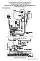
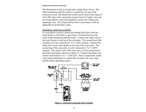
Electrical Connections continued-The thermostat switch is a single pole, single throw device. Thefield connections shall be used as a control for one leg of theelectrical circuit. The thermostat switch can be used in the range of24 to 480 volts with a maximum current load of 15 amps. Any andall wiring shall be sized and installed to satisfy the voltage andamperage used. All wiring shall be done in accordance with allapplicable local and state codes.GENERAL INSTALLATIONSIf a circulator is used to control the heating fluid flow from thewater heater to the boiler, a zone relay is required between thewater heater thermostat and the boiler. Connect the white wire onthe water heater to one leg of the circulator. The second leg of thecirculator is to be connected to “L2” (120V neutral). Connect thewhite wire on the water heater to one leg of the zone relay. Thesecond leg of the zone relay is to be connected to “L2” (120Vneutral). The contact side of the zone relay is to be connected tothe boiler operating control (see figure 5). Connect the black wireon the water heater to “L1” (120V hot). These connections enablewater heater thermostat to control the circulator, the zone relay,and the boiler operating control.Figure 5 – Electrical Connection with Circulator24