Design, fabrication and analysis of a body-caudal fin propulsion ...
Design, fabrication and analysis of a body-caudal fin propulsion ...
Design, fabrication and analysis of a body-caudal fin propulsion ...

Create successful ePaper yourself
Turn your PDF publications into a flip-book with our unique Google optimized e-Paper software.
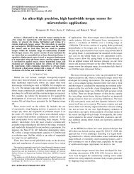
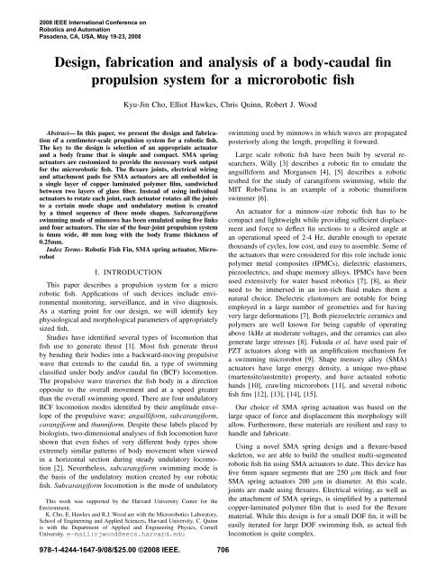
2008 IEEE International Conference onRobotics <strong>and</strong> AutomationPasadena, CA, USA, May 19-23, 2008<strong>Design</strong>, <strong>fabrication</strong> <strong>and</strong> <strong>analysis</strong> <strong>of</strong> a <strong>body</strong>-<strong>caudal</strong> <strong>fin</strong><strong>propulsion</strong> system for a microrobotic fishKyu-Jin Cho, Elliot Hawkes, Chris Quinn, Robert J. WoodAbstract— In this paper, we present the design <strong>and</strong> <strong>fabrication</strong><strong>of</strong> a centimeter-scale <strong>propulsion</strong> system for a robotic fish.The key to the design is selection <strong>of</strong> an appropriate actuator<strong>and</strong> a <strong>body</strong> frame that is simple <strong>and</strong> compact. SMA springactuators are customized to provide the necessary work outputfor the microrobotic fish. The flexure joints, electrical wiring<strong>and</strong> attachment pads for SMA actuators are all embedded ina single layer <strong>of</strong> copper laminated polymer film, s<strong>and</strong>wichedbetween two layers <strong>of</strong> glass fiber. Instead <strong>of</strong> using individualactuators to rotate each joint, each actuator rotates all the jointsto a certain mode shape <strong>and</strong> undulatory motion is createdby a timed sequence <strong>of</strong> these mode shapes. Subcarangiformswimming mode <strong>of</strong> minnows has been emulated using five links<strong>and</strong> four actuators. The size <strong>of</strong> the four-joint <strong>propulsion</strong> systemis 6mm wide, 40 mm long with the <strong>body</strong> frame thickness <strong>of</strong>0.25mm.Index Terms- Robotic Fish Fin, SMA spring actuator, MicrorobotI. INTRODUCTIONThis paper describes a <strong>propulsion</strong> system for a microrobotic fish. Applications <strong>of</strong> such devices include environmentalmonitoring, surveillance, <strong>and</strong> in vivo diagnosis.As a starting point for our design, we will identify keyphysiological <strong>and</strong> morphological parameters <strong>of</strong> appropriatelysized fish.Studies have identified several types <strong>of</strong> locomotion thatfish use to generate thrust [1]. Most fish generate thrustby bending their bodies into a backward-moving propulsivewave that extends to the <strong>caudal</strong> <strong>fin</strong>, a type <strong>of</strong> swimmingclassified under <strong>body</strong> <strong>and</strong>/or <strong>caudal</strong> <strong>fin</strong> (BCF) locomotion.The propulsive wave traverses the fish <strong>body</strong> in a directionopposite to the overall movement <strong>and</strong> at a speed greaterthan the overall swimming speed. There are four undulatoryBCF locomotion modes identified by their amplitude envelope<strong>of</strong> the propulsive wave: anguilliform, subcarangiform,carangiform <strong>and</strong> thunniform. Despite these labels placed bybiologists, two-dimensional analyses <strong>of</strong> fish locomotion haveshown that even fishes <strong>of</strong> very different <strong>body</strong> types showextremely similar patterns <strong>of</strong> <strong>body</strong> movement when viewedin a horizontal section during steady undulatory locomotion[2]. Nevertheless, subcarangiform swimming mode isthe basis <strong>of</strong> the undulatory motion created by our roboticfish. Subcarangiform locomotion is the mode <strong>of</strong> undulatoryThis work was supported by the Harvard University Center for theEnvironment.K. Cho, E. Hawkes <strong>and</strong> R.J. Wood are with the Microrobotics Laboratory,School <strong>of</strong> Engineering <strong>and</strong> Applied Sciences, Harvard University. C. Quinnis with the Department <strong>of</strong> Applied <strong>and</strong> Engineering Physics, CornellUniversity. e-mail:rjwood@eecs.harvard.eduswimming used by minnows in which waves are propagatedposteriorly along the length, propelling it forward.Large scale robotic fish have been built by several researchers.Willy [3] describes a robotic <strong>fin</strong> to emulate theanguilliform <strong>and</strong> Morgansen [4], [5] describes a robotictestbed for the study <strong>of</strong> carangiform swimming, while theMIT RoboTuna is an example <strong>of</strong> a robotic thunniformswimmer [6].An actuator for a minnow-size robotic fish has to becompact <strong>and</strong> lightweight while providing sufficient displacement<strong>and</strong> force to deflect <strong>fin</strong> sections to a desired angle atan operational speed <strong>of</strong> 2-4 Hz, durable enough to operatethous<strong>and</strong>s <strong>of</strong> cycles, low cost, <strong>and</strong> easy to assemble. Some <strong>of</strong>the actuators that were considered for this role include ionicpolymer metal composites (IPMCs), dielectric elastomers,piezoelectrics, <strong>and</strong> shape memory alloys. IPMCs have beenused extensively for water based robotics [7], [8], as theirneed to be immersed in an ion-rich fluid makes them anatural choice. Dielectric elastomers are notable for beingemployed in a large number <strong>of</strong> geometries <strong>and</strong> for havingvery large deformations [7]. Both piezoelectric ceramics <strong>and</strong>polymers are well known for being capable <strong>of</strong> operatingabove 1kHz at moderate voltages, <strong>and</strong> the ceramics can alsogenerate large stresses [8]. Fukuda et al. have used pair <strong>of</strong>PZT actuators along with an amplification mechanism fora swimming microrobot [9]. Shape memory alloy (SMA)actuators have large energy density, a unique two-phase(martensite/austenite) property, <strong>and</strong> have actuated robotich<strong>and</strong>s [10], crawling microrobots [11], <strong>and</strong> several roboticfish <strong>fin</strong>s [12], [13], [14], [15].Our choice <strong>of</strong> SMA spring actuation was based on thelarge space <strong>of</strong> force <strong>and</strong> displacement this morphology willallow. Furthermore, these materials are resilient <strong>and</strong> easy toh<strong>and</strong>le <strong>and</strong> fabricate.Using a novel SMA spring design <strong>and</strong> a flexure-basedskeleton, we are able to build the smallest multi-segmentedrobotic fish <strong>fin</strong> using SMA actuators to date. This device hasfive 6mm square segments that are 250 µm thick <strong>and</strong> fourSMA spring actuators 200 µm in diameter. At this scale,joints are made using flexures. Electrical wiring, as well asthe attachment <strong>of</strong> SMA springs, is simplified by a patternedcopper-laminated polymer film that is used for the flexurematerial. While this design is for a small DOF <strong>fin</strong>, it will beeasily iterated for large DOF swimming fish, as actual fishlocomotion is quite complex.978-1-4244-1647-9/08/$25.00 ©2008 IEEE. 706
Fig. 1. The concept <strong>of</strong> a BCF <strong>propulsion</strong> mechanism is based upona novel ’meso’-scale manufacturing paradigm called smart compositemicrostructures[16]. In this concept the spine is created with a sequence<strong>of</strong> rigid links separated by flexure joints.Fig. 2.A. Basic ConceptThe basic concept uses antagonistic actuation at each joint.II. DESIGNThe basic concept <strong>of</strong> the microrobotic fish is displayed inFig. 1 <strong>and</strong> is composed <strong>of</strong> a flexure-jointed composite fiberspine that will be covered with a PDMS skin. The motion<strong>of</strong> the <strong>caudal</strong> <strong>fin</strong> is driven by the SMA springs attached oneither side <strong>of</strong> each flexure(see Fig. 2). These are actuated insuccession to create a traveling waveform.B. Actuator SelectionIn past iterations <strong>of</strong> the BCF <strong>propulsion</strong> mechanism,straight SMA wires were used with little success since theforce generated by the wire was too large to allow for arobust attachment. The spring was adopted as it not onlydecreases the surplus <strong>of</strong> force, but also increases deflection,allowing for well over 100% strain. This excess strain createsmore motion in the tail <strong>and</strong> allows for ease in mounting, asthe spring can be stretched, attached, then actuated to returnto working length. The design <strong>of</strong> the spring has multipleparameters that must be considered based on the deflection<strong>of</strong> the spring, δ, <strong>and</strong> the spring constant, k, which are givenas follows[17]:δ = 8PD3 nGd 4 (1)k = Gd48D 3 (2)nwhere D is the spring diameter measured from center <strong>of</strong>wire on either side, d is the wire diameter, n is the number707Shear Modulus (MPa)87654320 100 200 300 400 500Temperature(degrees Celcius)Fig. 3. The shear modulus <strong>of</strong> the SMA can be adjusted by choice <strong>of</strong>annealing temperature.<strong>of</strong> active coils in the spring, P is the load, <strong>and</strong> G is the shearmodulus <strong>of</strong> SMA wire after annealing.Thus to adjust our spring constant k, we had three parametersto choose from: d, D, <strong>and</strong> n. We would like tominimize d as this decreases cooling time, <strong>and</strong> n was limitedby the length <strong>of</strong> spring needed. Therefore we were left withD to minimize as much as possible without decreasing thedeflection outside <strong>of</strong> a useful range. Therefore a spring index,D/d, was chosen between 2.5 <strong>and</strong> 3.However, one more parameter can be altered, namelyG, the shear modulus. The value <strong>of</strong> G for the austenitephase <strong>of</strong> a spring is around 3.77 MPa when the wire isplastically deformed into a coil <strong>and</strong> not annealed. This valuecan be increased to almost 7.8 MPa when annealed (seeFig. 3). By annealing slightly above 300 degrees (measuredexternally with a thermocouple-actual internal temperatureis higher) we were able to maximize the shear modulus. Byunderst<strong>and</strong>ing the annealing process <strong>and</strong> the model in eq.(1) <strong>and</strong> eq. (2), we are able to choose the geometry thatgives us the desired stress <strong>and</strong> strain required to achieve theindividual flexure motion.C. Flexure <strong>Design</strong>The flexures are designed to avoid buckling under normaloperation while remaining sufficiently compliant (comparedwith the actuator stiffness). Flexures are made with a customprocess using thin-film polymers s<strong>and</strong>wiched between rigidcomposite plates [16]. Polymers are chosen for resilience <strong>and</strong>high elastic strain limit (allowing large motions with compactgeometries) [18]. However, in this case, current needs to bepassed through each flexure to power more distal actuatorson adjacent segments. To accomplish this, we used patternedcopper laminated on a thin-film polymer. Therefore, we musttake special care in designing the flexure geometry to avoidplastic deformations while keeping the stiffness low. Tostart, the pseudo-rigid-<strong>body</strong> model <strong>of</strong> a compliant mechanismassumes that the flexure can be conceptually replaced by aperfect pin joint in parallel with a rotational flexure. Thespring constant <strong>of</strong> this flexure is:k θ = EIL(3)
Since this is a composite beam, we need to determine theeffective modulus <strong>and</strong> the second moment <strong>of</strong> area <strong>of</strong> theflexure to use in eq. 3. This is done using a st<strong>and</strong>ard transformationfor a composite beam. First, the width <strong>of</strong> the polymersection, w p is multiplied by a factor n which is the ratio <strong>of</strong>the modulus <strong>of</strong> the polymer to the modulus <strong>of</strong> the conductor(n = E p /E c ). This results in a transformed homogeneousbeam with modulus E c . Determining the second moment <strong>of</strong>area <strong>of</strong> this beam takes two steps: 1) determine the location<strong>of</strong> the neutral axis, <strong>and</strong> 2) use this neutral axis <strong>and</strong> theparallel axis theorem to calculate the second moment <strong>of</strong> area.Since the transformed area can be broken down into tworectangular areas, the location <strong>of</strong> the neutral axis is de<strong>fin</strong>edas follows:Fig. 4.Basic building blocks for motion creation: (a) C-type (b) S-type.Ȳ =∑ȳi A i∑Ai= (h p + h c /2)w c h c + (h p /2)nw p h pw c h c + nw p h p(4)where ȳ i are the distances from the bottom edge <strong>of</strong> the beamto the centroid <strong>of</strong> each area <strong>and</strong> A i is the area <strong>of</strong> each section.The second moment <strong>of</strong> area is now found as:I ′ = ∑ w i h 3 i12 + A id 2 i = w ch 3 c12 + w ch c(ȳc − Ȳ ) 2+nw p h 3 p+ nw p h p(ȳp −12Ȳ ) 2(5)Now the terms E c <strong>and</strong> I ′ can replace E <strong>and</strong> I ineq. 3 respectively. Next, we are interested in the maximumdeflection allowed by the strain limit <strong>of</strong> the flexure materials.This will be limited by the conductor, so we will only presentcalculations based upon the copper layer. From simple beamtheory, the maximum strain in a bending beam is related tothe beam deflection as follows:Lε maxθ max = (hc + h p − Ȳ ) (6)where ǫ max is the yield strain <strong>of</strong> copper. For a 1mmwide, 12µm thick copper conductor laminated on 5.75mmwide, 12.7µm thick polyimide, the rotational stiffness is< 0.25mNm/rad. This flexure can achieve > ±10 ◦ <strong>of</strong>motion without plastic deformation. However, we must alsoconsider beam buckling due to the axial loads from theSMA actuators. The Euler buckling criterion for this flexuremorphology is given as:F max = π2 E c I ′(0.5L) 2 (7)Therefore, this flexure can withst<strong>and</strong> >20N before buckling.In the case where this buckling strength is insufficient, wecan use alternative flexure designs such as an inversionflexure [19].D. Generating MotionBy coordinating the rotation <strong>of</strong> each joint, undulatorymotion can be created. A common method to create thesemotions is to drive each joint with an individual actuator <strong>and</strong>coordinate these rotations. However, we have designed oursystem so that a single mode can be created with a singleactuator, where each mode would represent a certain shape<strong>of</strong> the tail. A timed sequence <strong>of</strong> multiple modes would createan undulatory motion. This method simplifies the control <strong>and</strong>design <strong>of</strong> the system since it requires a single input to controlmultiple joints for a certain mode.A single mode can be created by connecting two basicbuilding blocks in series. Each building block is composed<strong>of</strong> multiple segments with an actuator fixed at the two endsegments. Every joint has a mechanical stopper that de<strong>fin</strong>esthe angle <strong>of</strong> each joint when the actuator is activated.Fig. 4 shows the two basic building blocks. C-type iscreated by having the actuator on one side, with the actuatorsfixed at the two end segments. S-type is created by havingan actuator fixed at one end, passing through the hole inthe middle segment, <strong>and</strong> connecting at the last segment onthe opposite side. The angle <strong>of</strong> the stopper limits the rotationangle <strong>of</strong> the joints <strong>and</strong> de<strong>fin</strong>es the shape. The actuator shouldbe able to generate enough force <strong>and</strong> displacement to rotatethe joints until all the stoppers touch the adjoining segments.As long as the actuator passes through an attachment point<strong>of</strong> each segment, there would be a single mode that canbe created by the activation <strong>of</strong> the actuator. Variation <strong>of</strong>these two building blocks can be created by changing thenumber <strong>and</strong> the length <strong>of</strong> segments <strong>and</strong> the stopping angles<strong>of</strong> each joint. Combining a mix <strong>of</strong> these two building blocksin series creates various mode shapes, each activated by asingle actuator.We have created subcarangiform swimming mode byusing the two basic building blocks discussed above. Fig. 5shows the resulting motion. There are two basic modes,where each mode has an antagonistic version. Modes (a)<strong>and</strong> (c) are series combination <strong>of</strong> two C-types <strong>and</strong> modes (b)<strong>and</strong> (d) are series combination <strong>of</strong> two S-types. The actuatorshown on each mode is a single actuator connected fromone end to the other. The four modes are activated with asequence <strong>of</strong> (a) to (d), <strong>and</strong> repeating the sequence creates acontinuous motion. Four actuators are connected to the <strong>body</strong>frame, one for each mode. They should provide enough force<strong>and</strong> displacement when activated to create each mode, butshould also be able to be elongated when other actuatorsare activated to create other modes. Again, this is a benefit<strong>of</strong> SMA coil actuators as opposed to straight SMA actuator708
Fig. 5. Subcarangiform BCF motion is created with four modes. Noticea traveling wave created as each mode is sequentially activated from (a) to(d).Fig. 6. Annealing <strong>of</strong> SMA spring actuators. (a) SMA wire is wound arounda conducting ’mold’ wire which heats the SMA wire during annealing. (b)Annealed SMA springs, unstretched <strong>and</strong> stretched (penny is shown at thebottom right side for size comparison).wires.III. FABRICATIONA. SMA Coil Actuator AnnealingIn order to achieve a spring-like geometry for a shapememory alloy, a high temperature annealing process is used.The annealing process begins by stretching a wire 2.5-3times the diameter <strong>of</strong> the SMA wire between two adjustableclamps. Two loops are then tied in either end <strong>of</strong> the SMA,one <strong>of</strong> which is hooked onto an anchor attached to the nearclamp <strong>and</strong> the other connected to a clip that is used as ah<strong>and</strong>le for winding. Depending on the length <strong>of</strong> the spring,the SMA wire is wound around the support wire 10-20 times,keeping the coil tight <strong>and</strong> closed (no space between loops).Multiple springs can be made on a single wire. Fig. 6-(a) shows the SMA wire wound around a conducting moldwire for the annealing process. The number <strong>of</strong> springs, <strong>and</strong>spacing between them are customized based on the force <strong>and</strong>displacement requirements <strong>and</strong> geometrical considerations.For the robotic fish, four springs with a wire diameter <strong>of</strong>760µm, each with 17 windings are wrapped with a spacing<strong>of</strong> about 0.8mm between each spring. After wrapping, theclip is attached to the clamp <strong>and</strong> a weight is hung to keeptension as the support wire deforms. Current is run throughthe mold wire until the desired temperature is attained (readfrom a thermocouple). The lead wire is cut <strong>and</strong> the springsare slid <strong>of</strong>f <strong>and</strong> tested before use. Fig. 6-(b) shows two set<strong>of</strong> springs, one before stretching <strong>and</strong> the other one stretched<strong>and</strong> ready to be attached to the <strong>body</strong> frame.B. Spine <strong>and</strong> Flexure FabricationTo overcome the limitations with traditional macro-scalemanufacturing techniques for sub-millimeter scale articulateddevices, we have developed a meso-scale rapid prototypingmethod called Smart Composite Microstructures(SCM) [16]. This process entails the use <strong>of</strong> laminated,laser-micromachined materials stacked to achieve a desiredcompliance pr<strong>of</strong>ile. Fig. 7 gives an overview <strong>of</strong> the SCMFig. 7. Overview <strong>of</strong> the laser micromachining step <strong>of</strong> the SCM process.First, composite prepreg(1) <strong>and</strong> thin-film polymer laminae are laser cut(2) todesired planform geometries(3). These laminae are then aligned, stacked(5-6), <strong>and</strong> cured to form the spine segments(7).process that is used to create the links <strong>and</strong> joints <strong>of</strong> themicrorobotic fish spine.A new method <strong>of</strong> using copper-laminated foils as the flexurematerial, electrical connection, <strong>and</strong> mechanical attachmentpoints for the SMA actuators was developed. Copperlaminatedpolyimide foil is used as the flexure layer, withtwo perpendicularly aligned glass fiber layers laminated onboth sides. The copper foil is masked using kapton tape <strong>and</strong>a pattern is created using a laser cutter (Versa Laser VLS3.5).The tape is peeled <strong>of</strong>f from the sections to be etched with aferric chloride solution. To align the features precisely, thepolyimide layer is etched twice. First the regions that are tobe cut through are etched, <strong>and</strong> a pattern for the copper areais created with the laser cutter on the etched polyimide layer.Then it is etched again to create the <strong>fin</strong>al shape. Fig. 8 showsthe fabricated polyimide layer.Two single layer glass fiber laminae are joined orthogonally,<strong>and</strong> cut with a laser. Two <strong>of</strong> these are cured withthe patterned copper-laminated polyimide to create the spineor the <strong>body</strong> frame. Fig. 9 shows the <strong>body</strong> frame with fourflexure joints, electrical wiring <strong>and</strong> the SMA attachment padsas well as positioning holes needed to assemble the stoppers.709
Fig. 8. Copper-laminated polyimide layer patterned <strong>and</strong> etched to accommodateelectrical wiring <strong>and</strong> attachment points for the SMA actuators.Bend angle (degrees)12010080602 2.5 3 3.5 4 4.5 5 5.5 6Time (seconds)Fig. 11.Antagonistic activation characteristics for a single joint.Fig. 9. Four-segment spine with electrical wiring, actuator attachment pads,stopper positioning holes <strong>and</strong> flexures.C. AssemblyFig. 10 shows the assembled robotic fish <strong>fin</strong> with fourjoints. The stoppers that de<strong>fin</strong>e the joint angles are fabricatedusing a rapid prototyping machine (Invision SR from 3D systems)with a plastic material (Visijet SR200). The stoppersare built as a mating set: one with pegs <strong>and</strong> the other withholes. They are attached on both sides <strong>of</strong> each joint throughthe positioning holes with epoxy. The stopping angle is 25degrees, <strong>and</strong> the height is 1.5mm. The SMA actuators aresoldered on the copper attachment pads with a sulfuric acidbased liquid flux <strong>and</strong> a silver bearing solder. This provideselectrical contacts as well as mechanical connections. Theactuators either pass through a hole at the center <strong>of</strong> eachsegment, or they pass under a hook(made <strong>of</strong> glass fiber) tomake sure they are positioned on top <strong>of</strong> the segments. Thetotal length <strong>of</strong> the four joint fish <strong>fin</strong> is 40mm, with a height<strong>of</strong> 6 mm. The thickness <strong>of</strong> the frame is approximately 250microns.IV. RESULTSIn order to characterize the robotic fish <strong>fin</strong>, a single jointwith a size <strong>of</strong> 1cm by 1cm with a SMA coil actuator withFig. 10.Completed robotic fish <strong>fin</strong> with four joints.Maximum bending angle (degrees)130120110100900.06 0.08 0.1 0.12 0.14 0.16 0.18Activation Time (sec)Fig. 12.Maximum bending angle for various activation times.a diameter <strong>of</strong> 100 µm was built <strong>and</strong> tested. It is driven bytwo MOSFETs, which are controlled using MathWorks xPCtarget real time control s<strong>of</strong>tware. The motion is captured witha video camera to analyze the bending angle <strong>of</strong> the joints.Fig. 11 shows an example <strong>of</strong> bending angle vs. time as weactivate the spring SMA actuator with 0.6 A for 0.12 sec,rest for 0.8 sec, then activate the antagonistic actuator. Inorder to choose the amount <strong>of</strong> activation time for a givencurrent we ran a series <strong>of</strong> trials where the time interval iscompared to maximum bending angle (e.g. see Fig. 12 for0.6 A). For each current we choose the time at which thesaturation point is reached, thus minimizing power input <strong>and</strong>preventing overheating.Energy efficiency increases with increasing current sincethe activation time decreases which also decreases theamount <strong>of</strong> heat loss during activation. As displayed inFig. 13, the activation time decreases exponentially withincreasing current. But the current amplitude will be limitedby the power supply that will eventually be on board.To activate a 100 µm wire diameter SMA spring actuator,current <strong>of</strong> 0.6 A is needed at 1.09 V. To get a maximumbending angle, 0.12 seconds is needed. Since a single cyclerequires the activation <strong>of</strong> two antagonistic actuators, 0.15Ware consumed per cycle. With a Lithium Polymer batteryrated at 20mAh with 3.7V nominal output <strong>and</strong> weight <strong>of</strong>1gram (Kokam SLB455018), about 1696 cycles can beperformed, assuming that the loses from other electroniccomponents are minimal. For a 2 Hz motion, this correspondsto a continuous operation time <strong>of</strong> around 14 minutes.The <strong>fin</strong>al robotic fish <strong>fin</strong> has been tested to activate eachmode shown in fig. 5. Each mode is created by activating the710
Activation Time (sec)21.510.500.25 0.3 0.35 0.4 0.45 0.5 0.55 0.6Current (mA)Fig. 13. Activation time decreases exponentially with the magnitude <strong>of</strong>current applied to the actuator.Fig. 14. Sequential activation <strong>of</strong> the four modes <strong>of</strong> the BCF <strong>propulsion</strong>mechanism.four actuators in sequence. There are few things that need tobe carefully considered. The actuators need to move freely inthe pass-through holes when changing from one mode to theother, <strong>and</strong> sufficient moment is needed to pull the segmentsthat are bent in the other direction in the previous mode.Fig. 14 shows the resulting shapes from an initial experiment<strong>of</strong> activating each mode.V. SUMMARY AND FUTURE WORKIn this paper, a <strong>body</strong> <strong>caudal</strong> <strong>fin</strong> <strong>propulsion</strong> system usingSMA spring actuators mounted on a multi-segmented, flexurebased frame has been presented. Eventually, the fish will bebuilt with integrated electronics <strong>and</strong> covered with a protectiveskin.The design <strong>and</strong> <strong>fabrication</strong> techniques presented are simple,robust, <strong>and</strong> scalable. By customizing the SMA springactuator, we can create an actuated flexure joint with a range<strong>of</strong> displacements <strong>and</strong> forces, instead <strong>of</strong> a set amount <strong>of</strong> strain<strong>and</strong> force that straight wire SMA actuators provide. Flexures,electrical wiring, <strong>and</strong> actuator attachment points are allembedded into a copper-laminated polyimide foil patternedwith copper traces, solder pads <strong>and</strong> other features neededfor assembly. This simplicity in design <strong>and</strong> <strong>fabrication</strong>, aswell as the fact that the actuator characteristics can becustomized, makes this device a very good c<strong>and</strong>idate fora backbone <strong>of</strong> various other small-scale robots. Undulatorymotion is created by using a sequence <strong>of</strong> mode shapes. Thisscheme <strong>of</strong> using a single actuator to create a single modethat coordinates multiple joint angles further simplifies thedesign <strong>and</strong> control <strong>of</strong> the device.Much progress can be made on both the design <strong>and</strong> control<strong>of</strong> the robot. Varying each segment length to fit the naturalmotion <strong>of</strong> a fish as well as increasing total number <strong>of</strong>segments will result in a more realistic tail motion. Control<strong>of</strong> this motion will also be optimized using PWM, allowingfor concurrent actuation <strong>and</strong> thus smoother motion.REFERENCES[1] M. Sfakiotakis, D. Lane, <strong>and</strong> J. Davies, “Review <strong>of</strong> fish swimmingmodes for aquatic locomotion,” J. <strong>of</strong> Oceanic Engineering, vol. 24,no. 2, pp. 237–252, 1999.[2] E. D. T. G. V. Lauder, Fish Biomechanics. San Diego: AcademicPress, 2006, vol. 23, ch. Hydrodynamics <strong>of</strong> Undulatory Propulsion,pp. 425–468.[3] A. Willy <strong>and</strong> K. H. Low, “Development <strong>and</strong> initial experiment <strong>of</strong>modular undulating <strong>fin</strong> for untethered biorobotic AUVs,” in 2005 Proc.IEEE Int. Conf. Robotics <strong>and</strong> Biomimetics (ROBIO), pp. 45–50.[4] K. Morgansen, V. Duindam, R. Mason, J. Burdick, <strong>and</strong> R. Murray,“Nonlinear control methods for planar carangiform robot fish locomotion,”in 2001 Proc. IEEE Int. Conf. Robotics <strong>and</strong> Automation, pp.427–343.[5] K. Morgansen, P. Vela, <strong>and</strong> J. Burdick, “Trajectory stabilization for aplanar carangiform robot fish,” in 2002 Proc. IEEE Int. Conf. Robotics<strong>and</strong> Automation, pp. 756–762.[6] G. S. Triantafyllou, M. S. Triantafyllou, “An efficient swimmingmachine,” Sci. Amer., pp. 64–70, 1995.[7] R. Kornbluh, R. Pelrine, J. Eckerle, <strong>and</strong> J. Joseph, “Electrostrictivepolymer artificial muscle actuators,” in 1998 Proc. IEEE Int. Conf.Robotics <strong>and</strong> Automation, vol. 3, pp. 2147–2154.[8] Y. Fu, E. C. Harvey, M. K. Ghantasala, <strong>and</strong> G. M. Spinks, “<strong>Design</strong>,<strong>fabrication</strong> <strong>and</strong> testing <strong>of</strong> piezoelectric polymer PVDF microactuators,”Smart Materials & Structures, vol. 15, no. 1, pp. 141–146, 2006.[9] T. Fukuda, T. Fukuda, A. Kawamoto, F. Arai, <strong>and</strong> H. Matsuura,“Mechanism <strong>and</strong> swimming experiment <strong>of</strong> micro mobile robot inwater,” in 1994 Proc. IEEE Int. Conf. Robotics <strong>and</strong> Automation,A. Kawamoto, Ed., vol. 1, pp. 814–819.[10] K.-J. Cho <strong>and</strong> H. Asada, “Multi-axis SMA actuator array for drivinganthropomorphic robot h<strong>and</strong>,” in 2005 Proc. IEEE Int. Conf. Robotics<strong>and</strong> Automation, pp. 1356–1361.[11] B. Trimmer, A. Takesian, B. Sweet, C. Rogers, D. Hake, <strong>and</strong>D. Rogers, “Caterpillar locomotion: A new model for s<strong>of</strong>t-bodiedclimbing <strong>and</strong> burrowing robots,” in 7th Int. Symp. Technology <strong>and</strong>the Mine Problem, 2006.[12] N. Ono, M. Kusaka, M. Taya, <strong>and</strong> C. Wang, “<strong>Design</strong> <strong>of</strong> fish <strong>fin</strong>actuators using shape memory alloy composites,” in 2004 Proc. SPIE,vol. 5388, pp. 305–312.[13] O. K. Rediniotis, L. N. Wilson, D. C. Lagoudas, <strong>and</strong> M. M. Khan,“Development <strong>of</strong> a shape-memory-alloy actuated biomimetic hydr<strong>of</strong>oil,”J. <strong>of</strong> Intelligent Material Systems <strong>and</strong> Structures, vol. 13, no. 1,pp. 35–49, 2002.[14] N. Shinjo <strong>and</strong> G. W. Swain, “Use <strong>of</strong> a shape memory alloy for thedesign <strong>of</strong> an oscillatory <strong>propulsion</strong> system,” IEEE Journal <strong>of</strong> OceanicEngineering, vol. 29, no. 3, pp. 750–755, 2004.[15] Z. Yonghua, L. Shangrong, M. Ji, <strong>and</strong> Y. Jie, “Development <strong>of</strong> anunderwater oscillatory <strong>propulsion</strong> system using shape memory alloy,”in 2005 IEEE Int. Conf. Mechatronics <strong>and</strong> Automation, vol. 4, pp.1878–1883.[16] R. Wood, S. Avadhanula, R. Sahai, E. Steltz, <strong>and</strong> R. Fearing, “Microrobotdesign using fiber reinforced composites,” J. <strong>of</strong> Mechanical<strong>Design</strong>, May 2008.[17] K. Otsuka <strong>and</strong> C. M. Wayman, Shape Memory Materials. Cambridge,UK: Cambridge University Press, 1998.[18] S. Avadhanula <strong>and</strong> R. Fearing, “Flexure design rules for carbon fibermicrorobotic mechanisms,” in 2005 Proc. IEEE Int. Conf. Robotics<strong>and</strong> Automation, pp. 1579–1584.[19] R. Wood, S. Avadhanula, M. Menon, <strong>and</strong> R. Fearing, “Microroboticsusing composite materials: The micromechanical flying insect thorax,”in 2003 Proc. IEEE Int. Conf. Robotics <strong>and</strong> Automation, vol. 2, pp.1842–1849.711