Motor Drive Module Design for Electric Care Bed - inass
Motor Drive Module Design for Electric Care Bed - inass
Motor Drive Module Design for Electric Care Bed - inass

Create successful ePaper yourself
Turn your PDF publications into a flip-book with our unique Google optimized e-Paper software.
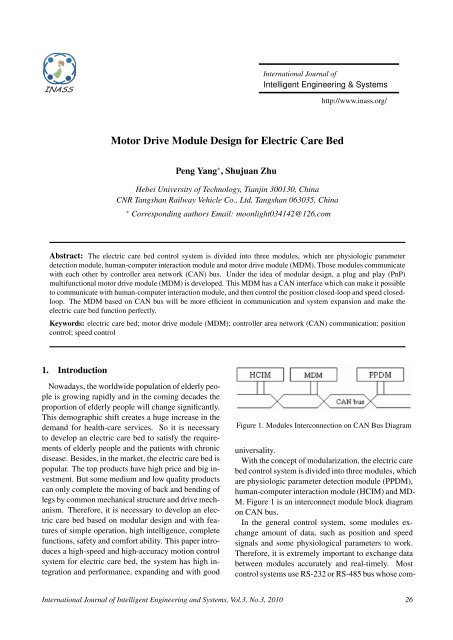
International Journal ofIntelligent Engineering & Systemshttp://www.<strong>inass</strong>.org/<strong>Motor</strong> <strong>Drive</strong> <strong>Module</strong> <strong>Design</strong> <strong>for</strong> <strong>Electric</strong> <strong>Care</strong> <strong>Bed</strong>Peng Yang ∗ , Shujuan ZhuHebei University of Technology, Tianjin 300130, ChinaCNR Tangshan Railway Vehicle Co., Ltd, Tangshan 063035, China∗ Corresponding authors Email: moonlight034142@126.comAbstract: The electric care bed control system is divided into three modules, which are physiologic parameterdetection module, human-computer interaction module and motor drive module (MDM). Those modules communicatewith each other by controller area network (CAN) bus. Under the idea of modular design, a plug and play (PnP)multifunctional motor drive module (MDM) is developed. This MDM has a CAN interface which can make it possibleto communicate with human-computer interaction module, and then control the position closed-loop and speed closedloop.The MDM based on CAN bus will be more efficient in communication and system expansion and make theelectric care bed function perfectly.Keywords: electric care bed; motor drive module (MDM); controller area network (CAN) communication; positioncontrol; speed control1. IntroductionNowadays, the worldwide population of elderly peopleis growing rapidly and in the coming decades theproportion of elderly people will change significantly.This demographic shift creates a huge increase in thedemand <strong>for</strong> health-care services. So it is necessaryto develop an electric care bed to satisfy the requirementsof elderly people and the patients with chronicdisease. Besides, in the market, the electric care bed ispopular. The top products have high price and big investment.But some medium and low quality productscan only complete the moving of back and bending oflegs by common mechanical structure and drive mechanism.There<strong>for</strong>e, it is necessary to develop an electriccare bed based on modular design and with featuresof simple operation, high intelligence, completefunctions, safety and com<strong>for</strong>t ability. This paper introducesa high-speed and high-accuracy motion controlsystem <strong>for</strong> electric care bed, the system has high integrationand per<strong>for</strong>mance, expanding and with goodFigure 1. <strong>Module</strong>s Interconnection on CAN Bus Diagramuniversality.With the concept of modularization, the electric carebed control system is divided into three modules, whichare physiologic parameter detection module (PPDM),human-computer interaction module (HCIM) and MD-M. Figure 1 is an interconnect module block diagramon CAN bus.In the general control system, some modules exchangeamount of data, such as position and speedsignals and some physiological parameters to work.There<strong>for</strong>e, it is extremely important to exchange databetween modules accurately and real-timely. Mostcontrol systems use RS-232 or RS-485 bus whose com-International Journal of Intelligent Engineering and Systems, Vol.3, No.3, 2010 26
Figure 2. <strong>Motor</strong> <strong>Drive</strong> Intelligent Node’s Block Diagrammunication means is the command and response mode.That is the host sends an inquiry to sub-controllers,and then sub-controllers upload the data of their ownstatus. The shortcoming of this approach is low datatransmission efficiency. As the host controller is busy,the sub-controller can’t upload data immediately andhas to wait <strong>for</strong> an order from the host. To overcomethe above shortcoming, three modules are combinedinto an intelligent network through CAN bus.Under the idea of modular design, a PnP (plug andplay) multifunctional MDM is developed. This MDMhas CAN interface that makes it possible to communicatewith HCIM, and then achieves the position closedloopand speed closed-loop.2. Intelligent CAN node-MDMIn this system, three modules are combined into anintelligent network through CAN bus. Each moduleconnects through CAN bus and among the modulesthere are multi-host communication relationships. So,each module is equipped with CAN interface, whichmakes them exchange data between each other. Figure2 is motor drive intelligent node’s block diagram.Human-computer interaction module controls the operationof actuator through CAN bus. Also the MDMtransmits real-time speed and position in<strong>for</strong>mation tohuman-computer interaction through CAN bus. In orderto adjust the position of body, the MDM use AT90-CAN128 as the controller, and then it can rapidly andeffectively control the action of linear actuator. Theactuator drives the electric care bed’s motion mechanism,and then the function of electric care bed iscompleted. In this paperthe CAN bus interface designand MDM speed and location of closed-loop controlare mainly introduced.The actuator has complex mechanism to transfer rotarymotion to linear motion. And it has the followingfeatures such as damping and noise-reducing, fullclosedand humidity resistance design. In the processof push-pull, the linear actuator has an internal limitedswitch in order to prevent actuator from locked,and then leads speed to zero; electric current is toolarge to burn motor boards.Using Hall sensor (3144) as the feedback component,these Hall-effect switches are monolithic integratedcircuits with tighter magnetic specifications aremore stable with both temperature and supply voltagechanges. The unipolar switching characteristic makesthese devices ideal <strong>for</strong> use with a simple bar or rodmagnet. Hall sensor is identical except <strong>for</strong> magneticswitching points. Each device includes a voltage regulator<strong>for</strong> reverse battery protection diode, quadraticHall-voltage generator, temperature compensation circuitry,small signal amplifier, Schmitt trigger, and withsuitable output pull up, they can be used with bipolaror CMOS logic circuits.3. CAN bus interface design3.1 CAN bus communication hardware designCAN bus, which supports distributed control or realtimecontrol, is a serial controller area network. CANcommunication hardware structure is shown in figure1. The hardware mainly includes single chip microcontrollerAT90CAN128, CAN bus transceiver ATA-6660 and high-speed optocoupler 6N137, etc.AT90CAN128 is a low-power CMOS 8-bit microcontrollerbased on the AVR enhanced RISC architecture.By executing powerful instructions in a singleclock cycle, the AT90CAN128 achieves throughputsapproaching 1 MIPS per MHz allowing systemdesigners to optimize power consumption versus processingspeed. The AT90CAN128 CAN controller isfully compatible with the CAN Specification 2.0 PartA and Part B. It delivers the features required to implementthe kernel of the CAN bus protocol accordingto the ISO/OSI Reference Model.ATA6660 is a high-speed CAN transceiver. It is especiallydesigned <strong>for</strong> high speed CAN Controller differentialmode data transmission between CAN-Controllersand CAN bus. It is fully compatible to ISO11-898. In normal case the RS pin connects to grounddirectly, so baud rate can be adjusted up to 1M/s.International Journal of Intelligent Engineering and Systems, Vol.3, No.3, 2010 27
In this system, CAN bus communication nodes isa multi-host, that is, any node can not only transmitmessages to other nodes, but also receive messagesfrom other nodes through CAN bus. Thus, each nodeneeds to allocate its own ID. Nodes distribution isshown in Table 1.Figure 3. Bus ArbitrationConsidering the anti-interference ability of CAN bus,AT90CAN128 is not directly linked to the ATA6660,but through the high-speed and per<strong>for</strong>mance optocoupler6N137 that is good <strong>for</strong> electrical isolation betweenthe CAN nodes and can speed up to 10Mb/s.In the hardware circuit design, AT90CAN128 with8MHz crystal frequency is mainly responsible <strong>for</strong> theinitialization of CAN communication, receiving-transmittingmessages. As a result of on-chip CAN controllers,the communication hardware circuit designcan be greatly simplified and system reliability can beenhanced.3.2 CAN bus communication software designThis section uses the integrated designer environmentAVR Sutdio4 and compiler AVR-GCC. The softwaredevelopment environment is provided by AtmelCompany. In communications, CAN-usb interface cardand CAN test software ZLGCAN Test are provided byZhouLiGong Company.3.2.1 The design of CAN protocolThe CAN protocol handles bus accesses accordingto the concept called ”Carrier Sense Multiple Accesswith Arbitration on Message Priority” (shown in Figure3).During transmission, arbitration on the CAN buscan be lost to a competing device with a higher priorityCAN identifier. This arbitration concept avoidscollisions of messages whose transmission was startedby more than one node simultaneously and makes surethe most important message is sent first without timeloss.The bus access conflict is resolved in the arbitrationfield mostly over the identifier value. If a data frameand a remote frame with the same identifier are initiatedat the same time, the data frame prevails over theremote frame.Table 1. CAN Nodes ID distributionNo.ID ID ID ID ID ID ID ID Node12 11 10 9 8 7 6 5 name0 0 0 0 0 0 0 0 1 MDM1 0 0 0 0 0 0 1 0 HCIM2 0 0 0 0 0 0 1 1 PPDM3 Reserved3.2.2 The program design of CAN communicationCAN bus communication is the basic part of the motordriving module software design, mainly including:receiving and processing messages from other nodeson CAN bus; sending the state news of this controller.CAN communication module includes CAN initializingprogram, data receiving procedure and data sendingprocedure.The following mainly describes the initializing programof CAN bus and the data transmission program.CAN bus initial function: can init (U8 mode) is used<strong>for</strong> some parameters of CAN bus, such as the bus baudrate initialized, empty CAN message box, and CANbus enabled, etc.U8 can init(U8 mode){if ((can fixed baudrate(mode))==0)return (0);can clear all mob();Can enable();return (1);}The procedures of CAN bus transmission programare as followsinitialize the following fields be<strong>for</strong>e sending:Identifier tag(IDT), Identifier extension (IDE),Remote transmission request (RTRTAG), Data length(DLC), Reserved bit tag (RBNTAG), Data bytes ofmessage (MSG); set the message boxe in Tx configuration<strong>for</strong> the Mob to send data or a remote frame;then the CAN channel scans all the message box inTx configuration, seeking <strong>for</strong> the message box havingthe highest priority and try to send it. All the parametersand data are available in the message box untila new initialization. The flowchart of AT90CAN128sending program is shown in Figure 4,International Journal of Intelligent Engineering and Systems, Vol.3, No.3, 2010 28
Figure 6. Motion control system <strong>Design</strong> of <strong>Electric</strong> <strong>Care</strong><strong>Bed</strong>representing that the MDM has received an order enteredby HCIM.4. Closed-loop motion control system design<strong>for</strong> electric care bedFigure 4. Flowchart of CAN Bus TransmissionFigure 5. Executive ResultsCAN bus transmission program is listed as follows:void can TX(void){message.id.std=0x0F;message.pt data = &buffer[0];message.ctrl.ide=0;message.dlc = 1;message.cmd = CMD TX DATA;while(can cmd(&message)!=CAN CMD ACCEPTED);while(1){}if (u8 temp == CAN STATUS ERROR)b=1;}Through CAN interface card, PC sends commandframe. The single-chip receiver enables the motorto implement corresponding movements and send theappropriate message in response to the CAN card, aftersending the appropriate message in response to thebus, while the PC machine receives messages and displayon the screen through the CAN debugging softwareZLGCAN Test. The executive results are shownin Figure 5.Figure 5 shows that the received frame identifier IDis 0x02402080. The Destination address is the user’sinput unit, the source address is the 1st motor executionunit, the data length is 1, and the value is 0x01,The motion control system <strong>for</strong> electric care bed hashigh integration, perfect function and user friendly interface.Three modules are combined into an intelligentnetwork through CAN bus. In order to adjust theposition of body, AT90CAN128 is used to rapidly andeffectively control the action of linear actuator. Theactuator drives the electric care bed’s motion mechanism,and then the function of electric care bed iscompleted.Closed-loop motion control system is composed ofa controller, a sensor, a drive mechanism and actuators.Figure 6 is the closed-loop motion control systemdesign of electric care bed.In Figure 6, U ∗ θ and U n ∗ represent position set valueand velocity set value. U ∗ θ and U n ∗ represent positionfeedback value and velocity feedback value respectively.Double closed loop control is implementedwith Hall sensor through signal of speed and position.Based on the software and hardware developmentplat<strong>for</strong>m, using the sensor and microcontroller technology,users can use the keyboard to control the electriccare bed to get the most com<strong>for</strong>table position andremember it. At the same time, users can control thespeed with control handle and set different speed accordingto their different requirements. In this way,the care bed design can achieve the MDM positionand speed control.4.1 Speed control of motion control systemSpeed control is achieved through pressing the up/down buttons to adjust the speed. Press the button(OK), the speed can be stored. If the speed needsto be modified, press the ”reset” button. In additionto these basic speed control functions, the followingfeatures like acceleration or deceleration can also beInternational Journal of Intelligent Engineering and Systems, Vol.3, No.3, 2010 29
Figure 7. AT90CAN128 and LMD18200 Interface CircuitAT90CAN128 receives speed and positionFigure 8. Ideal PWM Wave<strong>for</strong>madded. AT90CAN128 regulates PWM value to controlthe actuator.4.1.1 The design of speed control circuitThe LMD18200 is a 3A H-Bridge designed <strong>for</strong> motioncontrol applications. The device is built to usea multi-technology process which combines bipolarand CMOS control circuitry with DMOS power deviceson the same monolithic structure. Being ideal<strong>for</strong> driving DC and stepper motors; the LMD18200accommodates peak output currents up to 6A and operatesat supply voltages up to 55V.There are four timers / counters (16 bit T/C1 andT/C3, 8 bitT/C0 and T/C2). Timer/Counter0 is a generalpurpose, single channel, 8-bit Timer/Counter module.The 16-bit Timer/Counter unit allows accurateprogram execution timing (event management), wavegeneration, and signal timing measurement. Timer/Counter2is a general purpose, single channel, 8-bit Timer/Countermodule. The 16-bit timer / counter can generate10 independent interrupts, which adjust the PWMcycle. The 16-bit timer / counter with input captureunit which can be applied to record the external incidentas well as the time it has been lasted.AT90CAN128 and LMD18200 <strong>for</strong>m a unipolar drivingclosed-loop DC motor control circuit as shown inFigure 7. In this circuit, the PWM controls signal inputto pin 5 (connect with OC0A of AT90CAN128),turns signal input to pin 3 (connect with PC1 of AT9-0CAN128). The speed and direction are controlled byregulating PWM duty cycle. The position of actuatoris obtained by detecting the feedback signal of Hallsensor, which <strong>for</strong>ms the position closed loop controlto achieve precise control of actuator. feedback signal,and regulates PWM wave<strong>for</strong>m by T/C0, and thenthe actuator achieves a constant speed. The PWM resolution<strong>for</strong> the phase correct PWM mode is fixed toFigure 9. Flowchart of Speed Control Initializationeight bits. In phase correct PWM mode, the counteris incremented until the counter value matches MAX.When the counter reaches MAX, it changes the countdirection. The TCNT0 value will be equal to MAX <strong>for</strong>one timer clock cycle. Figure 8 is the ideal unipolarPWM wave<strong>for</strong>m.4.1.2 The software design of speed controlAT90CAN128 receives the message through the CANbus, and then controls the motor to start and stop, inthe <strong>for</strong>ward rotation acceleration / deceleration, andin the reverse acceleration / deceleration. This controlset the motors’ speed and directions mainly throughreceiving the display module’s message. The speedcontrol initialization flowchart is shown in Figure 9.Obtained pulse frequency through the input captureinterrupt, the program is as follows:International Journal of Intelligent Engineering and Systems, Vol.3, No.3, 2010 30
Figure 10. the Interface of Position SelectionSIGNAL(SIG INPUT CAPTURE1){ICP time=ICR1; capture();}int capture(){static int oldFall=0x00;int temp,newFall;newFall=ICR1;temp=newFall-oldFall;oldFall=newFall;return temp;}4.2 Position control of motion control systemSome products using electric motors are not onlylimited in the effect of start and shut control and directioncontrol, but also in short of the location controlor speed control. The following mainly introduces theposition control principle of the linear actuator mechanismwith position sensor. The position memory functioncan be applied to many of the controlled objectswhich do not require high accuracy such as electriccurtain, electric doors, electric seats, etc.Position control design can simplify the user’s operation.Users can operate the bed to the most com<strong>for</strong>tableposition, and then click “Position Memory key”to store the position. If users want to achieve this positionagain, click “Location 1” key, the actuator willpush bed to the last set position. For users, the positionmemory function can remember two positionsby pressing the “position 1”, “Location 2” key. Ifusers want to adjust the set position, just press “locationmemory” button, the user interface will appear(as shown in Figure 10).4.2.1 The hardware design of position control1. Absolute position control hardware designAbsolute position control is the benchmark runningposition of electric care bed. Using theHall sensor as reference position detection feedbackdevice, the output of these devices (Pin3) switches low when the magnetic field at theHall sensor exceeds the operating point threshold.At this point, the output voltage is VOUT.When the magnetic field is reduced below thereleasing point threshold, the device output goeshigh. The difference between the magnetic operatingand releasing points is called the hysteresisof the device. This built-in hysteresis allowsclean switching of the output even in thepresence of external mechanical vibration andelectrical noise.Hall sensor works as follows: When current Ion the magnetic field goes through the Hall sensor,if the current direction is perpendicular tothe magnetic field, the horizontal side of thesemiconductor substrate, which is between verticalsub-current and magnetic flux, generatesa voltage. The voltage is called Hall voltageUH. Hall voltage is proportional to the current(I) and magnetic induction (B), as shown in Eq.(3.1):U H = R H IB/d (3.1)Where R H is the hall coefficiency, d is the thicknessof the substrate, I is the electric current, Bis the magnetic induction. The current is constantand the Hall voltage is proportional to themagnetic induction (B), sizing only to the sizeof the magnetic induction, and has nothing todo with flux change rate. In this system, thereare four Hall sensors to control the electric carebed’s four postures. The sensor’s hardware designis shown in Figure 11. Pin 1 is connectedto +5V, to supply the voltage. Pin 2 is connectedto GND. Pin 3 is connected to the external interruptpin of AT90CAN128(PD0,PD1,PD2,PD3).2. Relative position control hardware designThe linear actuator with the position sensor, puttingretractable rod a lead, while the linear actuatorgives six pulses, through the controllerunit to capture the pulse count, and then controlthe position of electric care bed. The fol-International Journal of Intelligent Engineering and Systems, Vol.3, No.3, 2010 31
Figure 11. Hardware <strong>Design</strong> of Hall Sensorlowing introduces the interface between actuatorand drive circuit (shown in Figure 12).In the picture, the interface has four pins, asshown in Figure 9, signal 1 and signal 2 beingtwo outputs of internal position sensor. Whilethe sensor circuit in the actuator is OC gate, soit is necessary to build a pull-up resistor in peripheralcircuit of the internal position sensor,and then Signal 1 output pulse signal (shown inFigure 13).AT90CAN128 collects output pulses and calculatesthe number, frequency, comparing with thepredetermined value, and then controls the actuatorto reach the corresponding position andvelocity. Thus, it achieves electric care bed’sposition and speed control.4.2.2 The software design of position controlPosition control is divided into two parts, one beingabsolute position control, and the other being therelative position control.1. Absolute position controlTo control the position of MDM, reference positionshould be confirmed. Reference positionis designed to achieve through the Hall sensor,using four Hall sensors to control the referenceposition of back’s lifting/falling, leg bending andbody turning over.Horizontal position detection (Reference positiondetection) principle: The Hall sensor is aFigure 12. the Picture of Actuator InterfaceFigure 13. the Picture of Output Pulse Signalmagnetic sensor. When the S-pole of magnetcloses enough, the hall sensor output is low level,otherwise the output is high level. The sensor’soutput signal input AT90CAN128 the INT0, IN-T1, INT2, INT3 four external interrupts (PinPD0,PD1,PD2,PD3), and the falling edge triggerthe interrupt.The external interrupt initialization functions asfollows:void ex init(void){MCUCR=(1
Figure 14. Flowchart of Position Memory Subroutinesfirmed by edge detector, the input capture isinspired. At this time the value in TCNT1 iswritten to ICR1 and set ICF1. Interrupt at thistime is triggered through disruption of routinesto achieve the control of motor.For position control of MDM, it is primary todesign limited position of motor’s movement,and as a benchmark. Controller stores pulseswhen actuator achieves the limited position, thatis, actuator’s benchmark in the direction.Principle in calculating and memorizing location:there are manual buttons and store buttonson portable keyboard. The manual buttons cancontrol the linear actuator to achieve a appropriatelocation, while the single-chip calculatesfeedback pulses, and then if press the storagekey more than 3 seconds(t1 ≥ 3), this locationin<strong>for</strong>mation will be stored into the single-chipand memory function will have been completed(shown in Figure 14). Users can set two com<strong>for</strong>tablepositions according to their own requirements.5. ConclusionThis paper describes the hardware and software designof CAN bus communication and the position andspeed control design of electric care bed’s MDM. Thecommunication among MDM and other intelligent modulesmakes full use of the character of CAN bus thatit can transmit and receive message accurately, realtimelyand effectively. Under the idea of modular design,a PnP multifunctional MDM is developed. MDMcan communicate with human- computer interactionmodule through CAN bus, and then control the positionclosed-loop and speed closed-loop. This designcan make the electric care bed function perfectly.The intelligent motor drive module can be expandedto other system with CAN nodes. Memory function isthe expansion of position control. Due to the existenceof memory function, the MDM can be used into somesystems which need position control. The intelligentMDM enables operation simpler and convenient. TheMDM based on CAN bus has not only executive functions,but also control and communication functions.The module can be applied to some systems to improvethe extensibility and real-time per<strong>for</strong>mance ofthem. So the MDM will have better application anddevelopment value.6. AcknowledgmentsThis work was supported by the National Key TechnologyR&D Program under Grant No. 2006BAI22B03.References[1] Hande Alemdar, Cem Ersoy. Wireless sensor networks<strong>for</strong> healthcare: A survey. Comput. Netw. 2010.[2] Diaz, J., Rodriguez, E., Hurtado, L., Cacique, H.,Vazquez, N., Ramirez, “A. CAN bus embedded system<strong>for</strong> lighting network applications Circuits andSystems”, MWSCAS 2008. 51st Midwest Symposiumon 10-13 Aug, 2008: 531 - 534.[3] Huiqian Yang, Yaonan Wang, Xiaofang Yuan. “Developmentof Data Acquisition and Display Systemof HEV CAN BUS”, Computer Engineering and Applications,Vol.20 2006: 228-232.[4] Jiying Li. “Research on Frequency-shift Send Equipmentwith Microcomputer”, Journal of LanzhouJiaotong University (Natural Sciences Edition),Vol.26, No.1, 2007: 32-34.[5] Michael A.Goodrich, Alan C. Shultz. “A surveyFoundations and Trends in Human-computer Interaction”.Human-robot interaction. Vol.14, No.2, 2007.[6] Atmel. AT90CAN128-Datasheet-Revg, USA, AtmelCorporation, 2007.[7] Paolo Dario, Eugenio Guglielmelli, Vincenzo Genovese,Maurizio Toro. “Robot assistants: Applicationsand evolution”. Robotics and Autonomous Systems,Vol.18, No.3, 1996: 225-234.International Journal of Intelligent Engineering and Systems, Vol.3, No.3, 2010 33