Motor Drive Module Design for Electric Care Bed - inass
Motor Drive Module Design for Electric Care Bed - inass
Motor Drive Module Design for Electric Care Bed - inass

You also want an ePaper? Increase the reach of your titles
YUMPU automatically turns print PDFs into web optimized ePapers that Google loves.
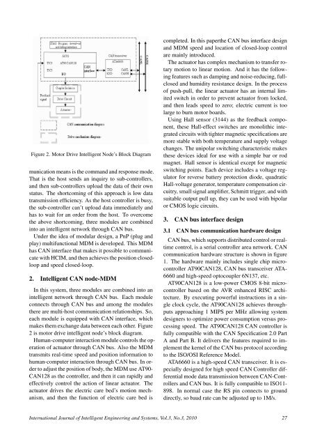
Figure 2. <strong>Motor</strong> <strong>Drive</strong> Intelligent Node’s Block Diagrammunication means is the command and response mode.That is the host sends an inquiry to sub-controllers,and then sub-controllers upload the data of their ownstatus. The shortcoming of this approach is low datatransmission efficiency. As the host controller is busy,the sub-controller can’t upload data immediately andhas to wait <strong>for</strong> an order from the host. To overcomethe above shortcoming, three modules are combinedinto an intelligent network through CAN bus.Under the idea of modular design, a PnP (plug andplay) multifunctional MDM is developed. This MDMhas CAN interface that makes it possible to communicatewith HCIM, and then achieves the position closedloopand speed closed-loop.2. Intelligent CAN node-MDMIn this system, three modules are combined into anintelligent network through CAN bus. Each moduleconnects through CAN bus and among the modulesthere are multi-host communication relationships. So,each module is equipped with CAN interface, whichmakes them exchange data between each other. Figure2 is motor drive intelligent node’s block diagram.Human-computer interaction module controls the operationof actuator through CAN bus. Also the MDMtransmits real-time speed and position in<strong>for</strong>mation tohuman-computer interaction through CAN bus. In orderto adjust the position of body, the MDM use AT90-CAN128 as the controller, and then it can rapidly andeffectively control the action of linear actuator. Theactuator drives the electric care bed’s motion mechanism,and then the function of electric care bed iscompleted. In this paperthe CAN bus interface designand MDM speed and location of closed-loop controlare mainly introduced.The actuator has complex mechanism to transfer rotarymotion to linear motion. And it has the followingfeatures such as damping and noise-reducing, fullclosedand humidity resistance design. In the processof push-pull, the linear actuator has an internal limitedswitch in order to prevent actuator from locked,and then leads speed to zero; electric current is toolarge to burn motor boards.Using Hall sensor (3144) as the feedback component,these Hall-effect switches are monolithic integratedcircuits with tighter magnetic specifications aremore stable with both temperature and supply voltagechanges. The unipolar switching characteristic makesthese devices ideal <strong>for</strong> use with a simple bar or rodmagnet. Hall sensor is identical except <strong>for</strong> magneticswitching points. Each device includes a voltage regulator<strong>for</strong> reverse battery protection diode, quadraticHall-voltage generator, temperature compensation circuitry,small signal amplifier, Schmitt trigger, and withsuitable output pull up, they can be used with bipolaror CMOS logic circuits.3. CAN bus interface design3.1 CAN bus communication hardware designCAN bus, which supports distributed control or realtimecontrol, is a serial controller area network. CANcommunication hardware structure is shown in figure1. The hardware mainly includes single chip microcontrollerAT90CAN128, CAN bus transceiver ATA-6660 and high-speed optocoupler 6N137, etc.AT90CAN128 is a low-power CMOS 8-bit microcontrollerbased on the AVR enhanced RISC architecture.By executing powerful instructions in a singleclock cycle, the AT90CAN128 achieves throughputsapproaching 1 MIPS per MHz allowing systemdesigners to optimize power consumption versus processingspeed. The AT90CAN128 CAN controller isfully compatible with the CAN Specification 2.0 PartA and Part B. It delivers the features required to implementthe kernel of the CAN bus protocol accordingto the ISO/OSI Reference Model.ATA6660 is a high-speed CAN transceiver. It is especiallydesigned <strong>for</strong> high speed CAN Controller differentialmode data transmission between CAN-Controllersand CAN bus. It is fully compatible to ISO11-898. In normal case the RS pin connects to grounddirectly, so baud rate can be adjusted up to 1M/s.International Journal of Intelligent Engineering and Systems, Vol.3, No.3, 2010 27