Motor Drive Module Design for Electric Care Bed - inass
Motor Drive Module Design for Electric Care Bed - inass
Motor Drive Module Design for Electric Care Bed - inass

You also want an ePaper? Increase the reach of your titles
YUMPU automatically turns print PDFs into web optimized ePapers that Google loves.
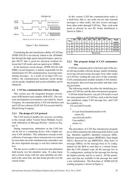
In this system, CAN bus communication nodes isa multi-host, that is, any node can not only transmitmessages to other nodes, but also receive messagesfrom other nodes through CAN bus. Thus, each nodeneeds to allocate its own ID. Nodes distribution isshown in Table 1.Figure 3. Bus ArbitrationConsidering the anti-interference ability of CAN bus,AT90CAN128 is not directly linked to the ATA6660,but through the high-speed and per<strong>for</strong>mance optocoupler6N137 that is good <strong>for</strong> electrical isolation betweenthe CAN nodes and can speed up to 10Mb/s.In the hardware circuit design, AT90CAN128 with8MHz crystal frequency is mainly responsible <strong>for</strong> theinitialization of CAN communication, receiving-transmittingmessages. As a result of on-chip CAN controllers,the communication hardware circuit designcan be greatly simplified and system reliability can beenhanced.3.2 CAN bus communication software designThis section uses the integrated designer environmentAVR Sutdio4 and compiler AVR-GCC. The softwaredevelopment environment is provided by AtmelCompany. In communications, CAN-usb interface cardand CAN test software ZLGCAN Test are provided byZhouLiGong Company.3.2.1 The design of CAN protocolThe CAN protocol handles bus accesses accordingto the concept called ”Carrier Sense Multiple Accesswith Arbitration on Message Priority” (shown in Figure3).During transmission, arbitration on the CAN buscan be lost to a competing device with a higher priorityCAN identifier. This arbitration concept avoidscollisions of messages whose transmission was startedby more than one node simultaneously and makes surethe most important message is sent first without timeloss.The bus access conflict is resolved in the arbitrationfield mostly over the identifier value. If a data frameand a remote frame with the same identifier are initiatedat the same time, the data frame prevails over theremote frame.Table 1. CAN Nodes ID distributionNo.ID ID ID ID ID ID ID ID Node12 11 10 9 8 7 6 5 name0 0 0 0 0 0 0 0 1 MDM1 0 0 0 0 0 0 1 0 HCIM2 0 0 0 0 0 0 1 1 PPDM3 Reserved3.2.2 The program design of CAN communicationCAN bus communication is the basic part of the motordriving module software design, mainly including:receiving and processing messages from other nodeson CAN bus; sending the state news of this controller.CAN communication module includes CAN initializingprogram, data receiving procedure and data sendingprocedure.The following mainly describes the initializing programof CAN bus and the data transmission program.CAN bus initial function: can init (U8 mode) is used<strong>for</strong> some parameters of CAN bus, such as the bus baudrate initialized, empty CAN message box, and CANbus enabled, etc.U8 can init(U8 mode){if ((can fixed baudrate(mode))==0)return (0);can clear all mob();Can enable();return (1);}The procedures of CAN bus transmission programare as followsinitialize the following fields be<strong>for</strong>e sending:Identifier tag(IDT), Identifier extension (IDE),Remote transmission request (RTRTAG), Data length(DLC), Reserved bit tag (RBNTAG), Data bytes ofmessage (MSG); set the message boxe in Tx configuration<strong>for</strong> the Mob to send data or a remote frame;then the CAN channel scans all the message box inTx configuration, seeking <strong>for</strong> the message box havingthe highest priority and try to send it. All the parametersand data are available in the message box untila new initialization. The flowchart of AT90CAN128sending program is shown in Figure 4,International Journal of Intelligent Engineering and Systems, Vol.3, No.3, 2010 28