Motor Drive Module Design for Electric Care Bed - inass
Motor Drive Module Design for Electric Care Bed - inass
Motor Drive Module Design for Electric Care Bed - inass

You also want an ePaper? Increase the reach of your titles
YUMPU automatically turns print PDFs into web optimized ePapers that Google loves.
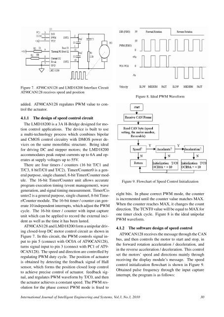
Figure 7. AT90CAN128 and LMD18200 Interface CircuitAT90CAN128 receives speed and positionFigure 8. Ideal PWM Wave<strong>for</strong>madded. AT90CAN128 regulates PWM value to controlthe actuator.4.1.1 The design of speed control circuitThe LMD18200 is a 3A H-Bridge designed <strong>for</strong> motioncontrol applications. The device is built to usea multi-technology process which combines bipolarand CMOS control circuitry with DMOS power deviceson the same monolithic structure. Being ideal<strong>for</strong> driving DC and stepper motors; the LMD18200accommodates peak output currents up to 6A and operatesat supply voltages up to 55V.There are four timers / counters (16 bit T/C1 andT/C3, 8 bitT/C0 and T/C2). Timer/Counter0 is a generalpurpose, single channel, 8-bit Timer/Counter module.The 16-bit Timer/Counter unit allows accurateprogram execution timing (event management), wavegeneration, and signal timing measurement. Timer/Counter2is a general purpose, single channel, 8-bit Timer/Countermodule. The 16-bit timer / counter can generate10 independent interrupts, which adjust the PWMcycle. The 16-bit timer / counter with input captureunit which can be applied to record the external incidentas well as the time it has been lasted.AT90CAN128 and LMD18200 <strong>for</strong>m a unipolar drivingclosed-loop DC motor control circuit as shown inFigure 7. In this circuit, the PWM controls signal inputto pin 5 (connect with OC0A of AT90CAN128),turns signal input to pin 3 (connect with PC1 of AT9-0CAN128). The speed and direction are controlled byregulating PWM duty cycle. The position of actuatoris obtained by detecting the feedback signal of Hallsensor, which <strong>for</strong>ms the position closed loop controlto achieve precise control of actuator. feedback signal,and regulates PWM wave<strong>for</strong>m by T/C0, and thenthe actuator achieves a constant speed. The PWM resolution<strong>for</strong> the phase correct PWM mode is fixed toFigure 9. Flowchart of Speed Control Initializationeight bits. In phase correct PWM mode, the counteris incremented until the counter value matches MAX.When the counter reaches MAX, it changes the countdirection. The TCNT0 value will be equal to MAX <strong>for</strong>one timer clock cycle. Figure 8 is the ideal unipolarPWM wave<strong>for</strong>m.4.1.2 The software design of speed controlAT90CAN128 receives the message through the CANbus, and then controls the motor to start and stop, inthe <strong>for</strong>ward rotation acceleration / deceleration, andin the reverse acceleration / deceleration. This controlset the motors’ speed and directions mainly throughreceiving the display module’s message. The speedcontrol initialization flowchart is shown in Figure 9.Obtained pulse frequency through the input captureinterrupt, the program is as follows:International Journal of Intelligent Engineering and Systems, Vol.3, No.3, 2010 30