Figure 10. the Interface of Position SelectionSIGNAL(SIG INPUT CAPTURE1){ICP time=ICR1; capture();}int capture(){static int oldFall=0x00;int temp,newFall;newFall=ICR1;temp=newFall-oldFall;oldFall=newFall;return temp;}4.2 Position control of motion control systemSome products using electric motors are not onlylimited in the effect of start and shut control and directioncontrol, but also in short of the location controlor speed control. The following mainly introduces theposition control principle of the linear actuator mechanismwith position sensor. The position memory functioncan be applied to many of the controlled objectswhich do not require high accuracy such as electriccurtain, electric doors, electric seats, etc.Position control design can simplify the user’s operation.Users can operate the bed to the most com<strong>for</strong>tableposition, and then click “Position Memory key”to store the position. If users want to achieve this positionagain, click “Location 1” key, the actuator willpush bed to the last set position. For users, the positionmemory function can remember two positionsby pressing the “position 1”, “Location 2” key. Ifusers want to adjust the set position, just press “locationmemory” button, the user interface will appear(as shown in Figure 10).4.2.1 The hardware design of position control1. Absolute position control hardware designAbsolute position control is the benchmark runningposition of electric care bed. Using theHall sensor as reference position detection feedbackdevice, the output of these devices (Pin3) switches low when the magnetic field at theHall sensor exceeds the operating point threshold.At this point, the output voltage is VOUT.When the magnetic field is reduced below thereleasing point threshold, the device output goeshigh. The difference between the magnetic operatingand releasing points is called the hysteresisof the device. This built-in hysteresis allowsclean switching of the output even in thepresence of external mechanical vibration andelectrical noise.Hall sensor works as follows: When current Ion the magnetic field goes through the Hall sensor,if the current direction is perpendicular tothe magnetic field, the horizontal side of thesemiconductor substrate, which is between verticalsub-current and magnetic flux, generatesa voltage. The voltage is called Hall voltageUH. Hall voltage is proportional to the current(I) and magnetic induction (B), as shown in Eq.(3.1):U H = R H IB/d (3.1)Where R H is the hall coefficiency, d is the thicknessof the substrate, I is the electric current, Bis the magnetic induction. The current is constantand the Hall voltage is proportional to themagnetic induction (B), sizing only to the sizeof the magnetic induction, and has nothing todo with flux change rate. In this system, thereare four Hall sensors to control the electric carebed’s four postures. The sensor’s hardware designis shown in Figure 11. Pin 1 is connectedto +5V, to supply the voltage. Pin 2 is connectedto GND. Pin 3 is connected to the external interruptpin of AT90CAN128(PD0,PD1,PD2,PD3).2. Relative position control hardware designThe linear actuator with the position sensor, puttingretractable rod a lead, while the linear actuatorgives six pulses, through the controllerunit to capture the pulse count, and then controlthe position of electric care bed. The fol-International Journal of Intelligent Engineering and Systems, Vol.3, No.3, 2010 31
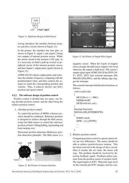
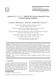
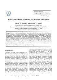
Figure 11. Hardware <strong>Design</strong> of Hall Sensorlowing introduces the interface between actuatorand drive circuit (shown in Figure 12).In the picture, the interface has four pins, asshown in Figure 9, signal 1 and signal 2 beingtwo outputs of internal position sensor. Whilethe sensor circuit in the actuator is OC gate, soit is necessary to build a pull-up resistor in peripheralcircuit of the internal position sensor,and then Signal 1 output pulse signal (shown inFigure 13).AT90CAN128 collects output pulses and calculatesthe number, frequency, comparing with thepredetermined value, and then controls the actuatorto reach the corresponding position andvelocity. Thus, it achieves electric care bed’sposition and speed control.4.2.2 The software design of position controlPosition control is divided into two parts, one beingabsolute position control, and the other being therelative position control.1. Absolute position controlTo control the position of MDM, reference positionshould be confirmed. Reference positionis designed to achieve through the Hall sensor,using four Hall sensors to control the referenceposition of back’s lifting/falling, leg bending andbody turning over.Horizontal position detection (Reference positiondetection) principle: The Hall sensor is aFigure 12. the Picture of Actuator InterfaceFigure 13. the Picture of Output Pulse Signalmagnetic sensor. When the S-pole of magnetcloses enough, the hall sensor output is low level,otherwise the output is high level. The sensor’soutput signal input AT90CAN128 the INT0, IN-T1, INT2, INT3 four external interrupts (PinPD0,PD1,PD2,PD3), and the falling edge triggerthe interrupt.The external interrupt initialization functions asfollows:void ex init(void){MCUCR=(1