5 Data transmission interfaces - ICAO
5 Data transmission interfaces - ICAO
5 Data transmission interfaces - ICAO

Create successful ePaper yourself
Turn your PDF publications into a flip-book with our unique Google optimized e-Paper software.
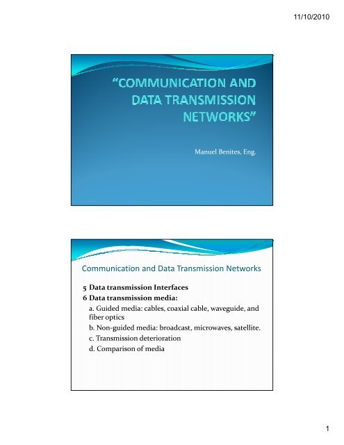
11/10/20105 <strong>Data</strong> <strong>transmission</strong> <strong>interfaces</strong>Definition of Interface:An interface is the frontier defined by common physicalinterconnection characteristics with properly definedexchange signals.5 <strong>Data</strong> <strong>transmission</strong> <strong>interfaces</strong>• Most of the recommendations includespecifications for signaling between the dataterminal equipment (DTE) and the data circuitterminal equipment (DCE).• In a limited way, they include procedures forsignaling between two DTEs.2
11/10/20105 <strong>Data</strong> <strong>transmission</strong> <strong>interfaces</strong>V.10 INTERFACE• This recommendation, dti entitled “Electriccharacteristics of double current asymmetric linkcircuits for general use with integrated circuitsequipment for data <strong>transmission</strong>”, specifies nonbalancedconnections.• The expression non‐balanced in this context meansthat every interface circuit has a live conductor andshares a common grounding with the other circuits.Voltage is measure with respect to grounding.5 <strong>Data</strong> <strong>transmission</strong> <strong>interfaces</strong>V.11 INTERFACE• This recommendation dti in the blue book is entitled:“Electric characteristics of double currentsymmetric link circuits for general use withintegrated circuits equipment for data<strong>transmission</strong>”.• The expression balanced in this context means thateach interface circuit has two conductors :• one for the signal, and• the other for return.4
11/10/20105 <strong>Data</strong> <strong>transmission</strong> <strong>interfaces</strong>V.11 INTERFACE• Symmetric link circuit means a symmetric generatorconnected to a symmetric receiver via asymmetricinterconnection pair.• In a symmetric generator, the algebraic sum of thepotentials of its two terminals in relation to thegrounding must be constant for all transmitted signals.5 <strong>Data</strong> <strong>transmission</strong> <strong>interfaces</strong>V.24 INTERFACE• This standard d entitled “List of definitions iti of thecircuits for the exchange between data terminalequipment and data circuit terminal equipment”is one of the most widely used and its importance restson the fact that it defines the functions of theexchange circuits that exist between the DTE(terminal) and the DCE (modem or multiplexor orconcentrator or node).5
11/10/20105 <strong>Data</strong> <strong>transmission</strong> <strong>interfaces</strong>V.24 INTERFACE• Withoutt these dfiiti definitions, it would not be possible toconnect equipment from different brands.• It regulates the exchange circuits for the transfer ofdata, control, timing, and grounding signals. Thisstandard does not specify the electric characteristics orthe physical dimensions of the circuits and theircorresponding connectors, which are established bystandards such as V.10. V.11 , and V.285 <strong>Data</strong> <strong>transmission</strong> <strong>interfaces</strong>V.24 INTERFACE• Standard d 2110 isused for thephysicalh ldimensions.i• V.24 is in a sense a super‐set of standards.• This standard applies to:• Synchronous and asynchronous communications• Dedicated and switched lines• 2‐ and 4‐ wire circuitsit• End‐to‐end and multipoint circuits• Certain public data networks6
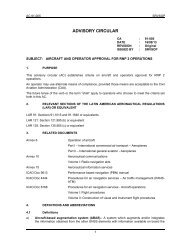
11/10/20105 <strong>Data</strong> <strong>transmission</strong> <strong>interfaces</strong>V.24 INTERFACE• This interface has two groups of circuits: the 100 seriesand the 200 series.• The circuits of the 100 series conform to standardV.24.• The circuits of the 200 series are used in accordancewith the application.5 <strong>Data</strong> <strong>transmission</strong> <strong>interfaces</strong>V.24 Half Duplex Operation7
11/10/20105 <strong>Data</strong> <strong>transmission</strong> <strong>interfaces</strong>V.24 Full Duplex Operation5 <strong>Data</strong> <strong>transmission</strong> <strong>interfaces</strong>V.28 INTERFACEThis recommendation, entitled “Electriccharacteristics of asymmetric link circuits fordouble current <strong>transmission</strong>”, specifies the electriccharacteristics of the interface (<strong>transmission</strong> andreception) between the modem and the terminal.8
11/10/20105 <strong>Data</strong> <strong>transmission</strong> <strong>interfaces</strong>V.35 INTERFACE• This interface is a combination of the V.35 standardand EIA standard 232, and is not a true CCITTconnector.• All dt data and timingi terminals conform to the V.35specification (balanced circuits and low voltage) andcontrol signals have EIA 232 voltages (non‐balanced).5 <strong>Data</strong> <strong>transmission</strong> <strong>interfaces</strong>V.35 INTERFACE• All data and timing pins are added to the V.35specification, which are balanced and low‐voltagecircuits.• Yet, all control pins are non‐balanced EIA‐232 voltages.• The test, local loop, and remote loop functions areassigned according to each manufacturer.9
11/10/20105 <strong>Data</strong> <strong>transmission</strong> <strong>interfaces</strong>V.36 INTERFACE• The recommended <strong>transmission</strong> speed for thisinterface is from 48 to 72 Kbps.• Recommendation V.10 defines the electriccharacteristics of its non‐balanced control andcommand lines.5 <strong>Data</strong> <strong>transmission</strong> <strong>interfaces</strong>V.36 INTERFACE• Balanced data and timing lines are regulated byrecommendation V.11.• Standard V.24 defines the functions of the otherinterface lines and has a 37‐pin connector (ISOstandard 4902).10
11/10/20105 <strong>Data</strong> <strong>transmission</strong> <strong>interfaces</strong>X.21 INTERFACE• The X.21 interface approach is to use more logic in theDTE‐DCE interface in order to provide less circuits.• Presently, X.21 is not used at logical level, but it is atphysical level, although very scarcely.5 <strong>Data</strong> <strong>transmission</strong> <strong>interfaces</strong>X.21 INTERFACE11
11/10/20105 <strong>Data</strong> <strong>transmission</strong> <strong>interfaces</strong>• The Electronic/Telecommunications IndustriesAssociation (EIA/TIA) and the Institute of Electricaland Electronic Engineers (IEEE) provide most of theengineering standards for communication equipment.•• The American National Standard Institute (ANSI)validates firm documents.5 <strong>Data</strong> <strong>transmission</strong> <strong>interfaces</strong>List of EIA/TIA Interfaces12
11/10/20105 <strong>Data</strong> <strong>transmission</strong> <strong>interfaces</strong>EIA‐232E (25‐pin) INTERFACE• In July 1991, the basic EIA‐232 standard was reviewedto achieve several things. One of them was toeliminate the EIA‐232D standard (a 9‐pin interface)since there was widespread misunderstanding that itwas replacing the old EIA RS‐232.• It originated from the telecommunications industryusing a small interface with the same electriccharacteristics as those of EIA 232.5 <strong>Data</strong> <strong>transmission</strong> <strong>interfaces</strong>EIA/TIA 232E (25‐pin) INTERFACE (cont.)• The standard that replaces the 9‐pin interface isANSI/EIA/TIA‐574‐1990 or EIA‐574.• Another greater revision of EIA‐232E was theintroduction of a smaller interface called EIA‐232E AltA, a 26‐pin interface.• This interface could become the interface of the futurebecause it is similar to the 9‐pin interface, but withmuch more capacity.13
11/10/20105 <strong>Data</strong> <strong>transmission</strong> <strong>interfaces</strong>EIA/TIA 232E (25‐pin) INTERFACE (cont.)• EIA‐232‐type <strong>interfaces</strong> are limited to 20 Kbps; for fasterspeeds, the recommendation is:• EIA‐530 standard (which replaces the EIA‐449 standard)• EIA‐561 standard (RJ45‐type or 8‐position miniature)• EIA‐574 standard (9‐pin replacement for EIA‐232B.• The EIA‐232 standard has a male interface for the dataterminal equipment (DTE) and a female connector for thedata communication equipment (DCE). It is necessary tofully verify the pins in the manufacturer’s manuals.5 <strong>Data</strong> <strong>transmission</strong> <strong>interfaces</strong>RS‐422A INTERFACE• This is an interface called “Balanced differentialelectric circuit interface”, which uses balanceddifferential‐voltage circuits, capable of high dataspeeds over distances greater than those of the RS‐232‐C standard and is fully compatible with V.11 and X.27recommendations.• Can transmit up to 100 Kbps at 1200 meters and up to10 Mbps at 12 m (40 feet)14
11/10/20105 <strong>Data</strong> <strong>transmission</strong> <strong>interfaces</strong>RS‐423A INTERFACE• Known as “Electric characteristics of non‐balancedvoltage interface digital circuits”, it is similar to theEIA RS‐232 C standard.• This interface is made up by bipolar voltage circuitswithout termination of one single terminal.• It has a range of 1200 meters at a speed of 3 Kbps or upto 12 meters at a speed of up to 300 Kbps.5 <strong>Data</strong> <strong>transmission</strong> <strong>interfaces</strong>RS‐366 INTERFACE Automatic calling unit• This standard defines the mechanical, electrical, andfunctional characteristics of the automatic calling unitplaced between the modem and the terminal. Itselectric characteristics are compatible with the RS 232Cstandard.15
11/10/20105 <strong>Data</strong> <strong>transmission</strong> <strong>interfaces</strong>RS‐499 INTERFACE• This interface, known as “37‐pin and 9‐pin generalpurpose interface for serial data exchangeequipment”, has all of the RS 232C capabilities.• Introduces 10 new exchange circuits to improveinterface characteristics.5 <strong>Data</strong> <strong>transmission</strong> <strong>interfaces</strong>RS‐499 INTERFACE• This interface establishes the standard for a 37‐pinconnector and a 9‐pin connector.• Allows speeds of up to 2 Mbps and increased length ofthe interconnection cable up to 200 m.16
11/10/20105 <strong>Data</strong> <strong>transmission</strong> <strong>interfaces</strong>RS‐499 INTERFACE• The 10 additional circuits defined in the RS 449 interface include:•• Three circuits for control and status of DCE test functions (circuit LL,local LL, and remote loop, and TM circuit test mode),• Two circuits for control and status of DCE transfer to atelecommunications facility (SS circuit, selective standby, and SBcircuit, standby indicator)• A circuit for the selection of the DCE <strong>transmission</strong> frequency (SFcircuit, select frequency).• A circuit that provides an out‐of‐service function under the terminalcontrol (DTE) (IS circuit, Terminal In Service)• A circuit to provide a new signal function (NS circuit, New Signal)• Two common wires5 <strong>Data</strong> <strong>transmission</strong> <strong>interfaces</strong>RS‐485 INTERFACE• Interface specialized in data acquisition processes.• The RS‐485 interface supports 32 drivers and 32receivers.• It uses half duplex, multi‐drop communications over 1or 2 twisted pairs.• A network using this interface can connect with 2 or 4wires, with a maximum length of 4000 feet because ituses differential voltage <strong>transmission</strong>.17
11/10/20105 <strong>Data</strong> <strong>transmission</strong> <strong>interfaces</strong>RS‐488 INTERFACE FOR PROGRAMMABLE INSTRUMENTS• This interface is designed for instrumentation systemsthat require limited‐distance communications (about20 meters).• This standard defines as many variables as possible,without defining the use of the interface, or giving areference of the hardware used for its implementation.5 <strong>Data</strong> <strong>transmission</strong> <strong>interfaces</strong>ANSI/EIA‐530 INTERFACE• The EIA‐530 is the answer to claims about the large size ofthe EIA RS‐449 37‐pin interface, while retaining thefrequency spectrum of up to 2 Mbps.• Presently, the EIA 530 interface uses the same mechanicalconnector as the EIA‐232 standard, but uses the balancedvoltages of the EIA‐422 A standard or the non‐balancedvoltages of the EIA‐423 A standard.18
11/10/20105 <strong>Data</strong> <strong>transmission</strong> <strong>interfaces</strong>ANSI/EIA‐530 INTERFACE• While it is physically possible to connect a EIA‐530 to aEIA‐232, they are not compatible. Voltages are different anddo not have the same pin designations.• When balanced voltages are used, pins labeled A and B areused for each corresponding circuit.If non‐balancedvoltages are used, the interface will only use pins labeledwith letter A and the common signal return pin.5 <strong>Data</strong> <strong>transmission</strong> <strong>interfaces</strong>ANSI/EIA‐574 INTERFACE• The EIA/TIA‐574 interface replaces the EIA‐232Dinterface, but in essence, it creates a new 9‐pinconnector.• This connector is not electronically compatible withthe EIA‐232D standard, which uses 5 to 15 volt signalsand accepts speeds below 20 Kbps.• This new 9‐pin interface is capable of faster dataspeeds and is driven by a +/‐ volt power unit. What isinteresting is that it uses the same female plugconnections.19
11/10/20105 <strong>Data</strong> <strong>transmission</strong> <strong>interfaces</strong>RJ‐11 – RJ‐12 VOICE INTERFACE• Connectors for telephone units are mini‐modular modular 4‐pin(RJ‐11) and 6‐pin (RJ‐12) jacks, and connector cables havemale connectors on either end.• Since most telephone operations only use two‐wire devices,some connectors will have only 4 contacts, in this casecontacts 1 and 6 are not placed.• Having four connectors is excessive for the two‐wireoperation, but is suitable for four‐wire devices.6 <strong>Data</strong> <strong>transmission</strong> mediaa. Guided media: cables, coaxial cable, waveguide, andfb fiber opticsb. Non‐guided media: broadcast, microwaves, satellite.c. Transmission impairmentd. Comparison of media20
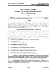
11/10/20106 <strong>Data</strong> <strong>transmission</strong> mediaa. Guided media:• Twisted pair cable• Coaxial cable• Waveguide• Fiber Optics6 <strong>Data</strong> <strong>transmission</strong> mediaTwisted pair cable•Consists of two isolated copper wires in a regular spiral pattern.Typically, a set of these pairs is grouped to make a multi‐pair cable,wrapped in a thick protection cladding.•Threads or wires are between 0,016 and 0,036 inches (0,040 mm to0,129 mm) thick, which correspond to gauges 26 to 16•Common gauges are 19, 22, 24, and 26. Cables are twisted togetherinto a regular spiral pattern of 2 to 6 inch full twist, to minimizei iinterference by placing adjacent pair in multi‐pair cables.21
11/10/2010Figure 4‐4Twisted‐Pair CableFigure 4‐5Shielded Twisted‐Pair Cable22
11/10/20106 <strong>Data</strong> <strong>transmission</strong> mediaa. Guided <strong>transmission</strong> media: cables, coaxial, waveguide, and fiberopticsTwisted‐pair cable• Analog <strong>transmission</strong> signals• Voice signals can be transmitted to a distance of 6kilometer, without repeaters.• The reason is that the loss at voice level is 1 dB/km.• To transmit point‐to‐point analog signals, a bandwidthof up to 1.1 MHz can be used.6 <strong>Data</strong> <strong>transmission</strong> mediaa. Guided media: cables, coaxial, waveguide, and fiber opticsTwisted‐pair cable• Digital signal <strong>transmission</strong>• For point‐to‐point digital lines, it is possible to transmitup to 4 Mbps of data, and even more, depending on thelength of the pair.• Susceptible to noise and interference because it caneasily couple to electromagnetic loads.• Easily affected by impact noise. For example, a pair laidin parallel to a 60‐Hz power line will be easily induced.23
11/10/20106 <strong>Data</strong> <strong>transmission</strong> mediaa. Guided media: cables, coaxial, waveguide, and fiber opticsTwisted pair cable applications• It is the most widely used medium for sending bothanalog and digital signals.• Used in the telephone system (backbone) and in thetelephone subscriber loop.• The human voice frequency range is between 20 Hz and20 KHz; only a 300 to 3400 Hz standard bandwidth isrequired to transmit intelligible voice.6 <strong>Data</strong> <strong>transmission</strong> mediaa. Guided media: cables, coaxial, waveguide, and fiber opticsTwisted pair cable applications• Digital data can be sent to moderate distances. For locallinks, typically a 28,8‐Kbps modem is needed.• It is possible to transmit signals on base or digital band.For example, it is possible to transmit a T1 circuit (USA)with 24 PCM voice channels which make up anaggregate of 1.544 Mbps or an E1 (ITU‐T) circuit with 30PCM voice channels making up a 2.048‐Mbps link.24
11/10/20106 <strong>Data</strong> <strong>transmission</strong> mediaa. Guided media: cables, coaxial, waveguide, and fiber optics• Coaxial cable• Coaxial cable consists of two conductors, but builtdifferently from the twisted pair and has a broaderfrequency range.• It is a hollow cylindrical outer conductor that surroundsan inner one‐wire conductor.• The internal conductor can be solid or have multiplewires, and is kept in its position by regularly‐spacedinsulating rings or by solid dielectric material.Coaxial Cable25
11/10/20106 <strong>Data</strong> <strong>transmission</strong> mediaa. Guided media: cables, coaxial, waveguide, and fiber optics• Coaxial cable <strong>transmission</strong> characteristics• Analog and digital signals can be transmitted. Longdistance systems can be analog or digital.• The 50‐ohm cable is used only for digital <strong>transmission</strong>(in base band), for which Manchester band base codingis used. It reaches speeds over 10 Mbps.• For these signals, repeaters are needed approximatelyevery kilometer; a smaller spacing permits higherspeeds. Experimental systems permit speeds of up to800 Mbps with a 1,6‐Km spacing.6 <strong>Data</strong> <strong>transmission</strong> mediaa. Guided media: cables, coaxial, waveguide, and fiber optics• Coaxial cable <strong>transmission</strong> characteristics• The 75‐ohm cable is used for both analog and digital<strong>transmission</strong>. For analog <strong>transmission</strong>, the frequencyrange is 300 to 400 MHz. For CATV, television channelsare placed on a 6‐MHz bandwidth.• The 75‐ohm cable is used for cable television or CATV(Community Antenna TeleVision). In this case, analogsignals are transmitted using frequency‐divisionmultiplexing, called broadband <strong>transmission</strong>.26
11/10/20106 <strong>Data</strong> <strong>transmission</strong> mediaa. Guided media: cables, coaxial, waveguide, and fiber optics• Coaxial cable <strong>transmission</strong> characteristics• Digital high‐speed <strong>transmission</strong> can also be achieved bymodulating analog signals; in this case, it is known assingle‐channel broadband.6 <strong>Data</strong> <strong>transmission</strong> mediaa. Guided media: cables, coaxial, waveguide, and fiber optics• Coaxial cable <strong>transmission</strong> characteristics• The coaxial cable provides a response at a frequencyhigher than the twisted pair; this is why it is used to carryhigher frequencies and faster data speeds.• It is less susceptible to interference and diaphone thanthe twisted pair.27
11/10/20106 <strong>Data</strong> <strong>transmission</strong> mediaa. Guided media: cables, coaxial, waveguide, and fiber optics• Coaxial cable <strong>transmission</strong> characteristics• Major performance limitations: abatement, thermalnoise, and inter‐modulation noise.• The latter is present only when several FDM channels orfrequency bands are transmitted.6 <strong>Data</strong> <strong>transmission</strong> mediaa. Guided media: cables, coaxial, waveguide, and fiber optics• Coaxial cable• To achieve a suitable signal quality, a given S/N relationmust be maintained. There are two commitmentvariables:• a) the strength of the signal, and• b) the spacing between amplifiers.• S/N relation can be increased by placing amplifierscloser to each other to amplify the signal with higherfrequency.28
11/10/20106 <strong>Data</strong> <strong>transmission</strong> mediaa. Guided media: cables, coaxial, waveguide, and fiber optics• Coaxial cable applications• It is the most versatile media and is used as LAN networkbackbone for long distance telephony and for televisiondistribution.• Uses the frequency‐division multiplexing technique(FDM) and can carry more than 10.000 voice channelssimultaneously.<strong>Data</strong> <strong>transmission</strong> mediaGuided media: cables, coaxial, waveguide, and fiber opticsWaveguide• At high frequencies, <strong>transmission</strong> lines and coaxialcables show high attenuation.• Waveguides reduce the attenuation of highfrequency signals.29
11/10/2010<strong>Data</strong> <strong>transmission</strong> mediaa. Guided media: cables, coaxial, waveguide, and fiber opticsWaveguide• Waveguides are generally pipe‐shaped structures made ofrectangular‐, circular‐ or elliptic‐sectioned material, inwhich the electromagnetic energy is conducted along theguide and is bound to its limits.• Theconductingwallsofthepipeconfinethewaveinsidebyreflection due to the Snell Law on the surface, where thepipe can be empty or full with a dielectric. The dielectricgives the pipe mechanical support (walls can be thin), burreduces propagation speed.<strong>Data</strong> <strong>transmission</strong> mediaa. Guided media: cables, coaxial, waveguide, and fiber optics• There are many types of waveguides. The most importantones are the following:• Rectangular (circular, elliptic) waveguide: The one whose crosssectionis rectangular (circular, elliptic).• Beam waveguide: It consists of a succession of lenses or mirrorscapable of guiding gan electromagnetic wave.• Ridge waveguide: Made up by two coaxial metal cylinders joinedalong their entire length by a metal radial ridge.30
11/10/2010<strong>Data</strong> <strong>transmission</strong> mediaa. Guided media: cables, coaxial, waveguide, and fiber optics• There are many types of waveguides. The most importantones are the following:• Grooved waveguide, V‐guided; H‐guided: Rectangularwaveguide that includes inner conducting ribs along each ofthe bigger walls.• Periodically‐loaded waveguide: Waveguide in which thepropagation is determined by regularly‐spaced variations of theproperties of the medium, the dimensions of the medium, orthe contour surfaces.• Dielectric waveguide: Consisting wholly of one or severaldielectric materials, with no conducting wall.<strong>Data</strong> <strong>transmission</strong> mediaa. Guided media: cables, coaxial, waveguide, and fiber optics31
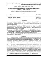
11/10/2010<strong>Data</strong> <strong>transmission</strong> mediaa. Guided media: cables, coaxial, waveguide, and fiber optics6 <strong>Data</strong> <strong>transmission</strong> mediaa. Guided media: cables, coaxial, waveguide, and fiber opticsFiber optics• Fiber optics is a <strong>transmission</strong> medium made of glassor plastic, thin and flexible (2 to 125 μm) capable ofcarrying an optical beam.• A fiber optic cable is cylindric and consists of threeconcentric sections:• core,• cladding, and• jacket.32
11/10/20106 <strong>Data</strong> <strong>transmission</strong> mediaa. Guided media: cables, coaxial, waveguide, and fiber opticsFiber optics• The core, which is the innermost part, consists of oneor more very thin threads (or fibers) made of glass orplastic.• Each fiber is covered by cladding, made of glass orplastic too, but with optical properties that differfrom those of the core.• The outer layer, called jacket, is made of plastic andother materials to protect it from humidity, abrasion,rupture and the environment.Fiber Optics Construction33
11/10/20106 <strong>Data</strong> <strong>transmission</strong> mediaa. Guided media: cables, coaxial, waveguide, and fiber optics• Fiber optics• In multimode propagation, the light from the sourcecomes in through the glass core. The low‐angle beams arereflected and propagated through the fiber, while otherbeams are absorbed by the cladding that surrounds thecore.• If we reduce the radius of the core, few light beams arereflected;andifwereducetheradiustotheorderofthewavelength, only one angle of mode will pass. Thispropagation mode is known as mono‐mode.Propagation Modes34
11/10/2010Refraction and Reflection6 <strong>Data</strong> <strong>transmission</strong> mediab. Non‐guided media: broadcast, microwaves, satellite.• Non‐Guided Media• These media include ground microwaves, satellite microwaves, andradio. For these media, unlike the guided media, the bandwidth ofthe signal produced by the transmitting antenna is more importantthan the medium for determining the <strong>transmission</strong> characteristics.• Hence, the higher the central frequency of the signal, the greaterthe potential bandwidth, and thus the faster the digital<strong>transmission</strong>.35
11/10/2010Radio communication BandsElectromagnetic SpectrumFrequency λ Application10 KHz 30 Km. Low frequencies for underwatercommunications100 KHz 3 Km. Long‐wave broadcast1 MHz 300 m AM broadcast10 MHz 30 m Short radio waves (ionosphere)100 MHz 3 m FM <strong>transmission</strong>150 MHz 2 m Mobile radio300 MHz 1 m Microwave links for point‐topointUHF and UHF TV boadcast3‐60 GHz 10 cm ‐ 0.5 cm Microwave links36
11/10/2010Microwave electromagnetic spectrumBandRange in GHzL 1‐2S 2‐4C 4‐8X 8‐12Ku 12‐18K 18‐26Ka 26‐40U 40‐60V 50‐75E 60‐90Frequency bands for microwave linksBand Range Comments2GH GHz 17 1.7 - 27GH 2.7 GHz Now designated d as mobile bands for PCSand DECT4 GHz 3.8 - 4.2 GHz Typical operator’s bands, high capacity6 GHz 5.9 - 7.1 GHz Typical operator’s bands, high capacity7/8 GHz 7.1-8.5 GHz Average lengths for high capacities11 GHz 10.7-11.7 GHz Operator’s traditional public bands, highcapacity37
11/10/20106 <strong>Data</strong> <strong>transmission</strong> mediab. Non‐guided media: broadcast, microwaves, satellite.• Non‐guided media• Another property of the signals transmitted by antennae isdirectionality. In general, at lower frequencies, signals areomnidirectional, and at higher frequencies, the signal can befocused on a directional beam• There are 2 frequency ranges of these media that are relevant forthis topic:• Microwave frequencies in a range from2to40 GHz. At thesefrequencies, highly directional beams are possible and easilyadjustable for point‐to‐point <strong>transmission</strong>s.• 30‐MHz to 1‐GHz range frequencies are used for omnidirectional<strong>transmission</strong> and are appropriate for broadcasting6 <strong>Data</strong> <strong>transmission</strong> mediab. Non‐guided media: broadcast, microwaves, satellite.Broadcast• Themaindifferencebetweenradioandmicrowavesisthat radio is generally omnidirectional and microwavesare very focused. No disk‐type antenna required.• The 30‐MHz to 1‐GHz range is very useful for broadcastcommunications. Radial waves are less sensitive to rainattenuation than microwave signals.38
11/10/20106 <strong>Data</strong> <strong>transmission</strong> mediab. Non‐guided media: broadcast, microwaves, satellite.Broadcast• However, for data <strong>transmission</strong>, its low speed is adisadvantage (in Kbps instead of Mbps).• One of the main reasons for radio wave degradation isinterference by multiple paths. These are created by thereflection of land, water or natural or man‐madeobjects. This effect is manifest when the television setshows many images when an aeroplane passes by.6 <strong>Data</strong> <strong>transmission</strong> mediab. Non‐guided media: broadcast, microwaves, satellite• Broadcast39
11/10/20106 <strong>Data</strong> <strong>transmission</strong> mediab. Non‐guided media: broadcast, microwaves, satellite• Non‐guided media• A digital microwave radio is defined as a radioequipment in which one or more properties (amplitude,frequency and phase) of the radiofrequency signal isquantified by a modulating signal.• The term digital implies a discrete set of levels ofamplitude, frequency or phase as a result of amodulating sign. Let us assume that the modulatingsignal is a serial stream of synchronous bits.Frequency bands for microwave linksBand Range Comments13 GHz15 GHz18 GHz23 GHz26 GHz12.7 - 13.3GHz14.4 - 15.4GHz17.7-19.7GHz21.22 - 23.6GHz24.5 - 26.5GHzTypically low to mediumcapacitiesAll capacitiesOperator’s traditional publicband for medium capacitiesAll capacitiesAll capacities38 GHz 37 - 39.5 GHz All capacities40
11/10/20106 <strong>Data</strong> <strong>transmission</strong> mediab. Non‐guided media: broadcast, microwaves, satellite• Medios No Guiados6 <strong>Data</strong> <strong>transmission</strong> mediab. Non‐guided media: broadcast, microwaves, satellite• Non‐guided media• There are three generic modulation techniques:• Amplitude Modulation ‐ AM,• Frequency Modulation – FM, and• Phase Modulation – PM.• In industry terminology, the letters “SK” are usually added to thefirst letter of the modulation type, such as ASK meaning AmplitudeShift Keying; FSK, Frequency Shift Keying, and PSK, Phase ShiftKeying41
11/10/20106 <strong>Data</strong> <strong>transmission</strong> mediab. Non‐guided media: broadcast, microwaves, satellite6 <strong>Data</strong> <strong>transmission</strong> mediab. Non‐guided media: broadcast, microwaves, satellite• Non‐guided media42
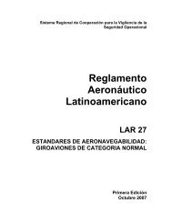
11/10/20106 <strong>Data</strong> <strong>transmission</strong> mediab. Non‐guided media: broadcast, microwaves, satellite• Satellite• A communications satellite is in essence a microwave repeater station.Essentially, a satellite is a radio repeater in the sky (transponder).• The satellite is used to link two or more microwave transmitters/receivers,known as earth stations.• The satellite receives <strong>transmission</strong>s over a frequency band (uplink),amplifies (analog <strong>transmission</strong>s) or repeats (digital <strong>transmission</strong>s) thesignal, and then retransmits it on another frequency (downlink).• Only one system will operate on a given number of frequency bands calledtransponder channels or simply transponders.Figure 4‐20Terrestrial Microwave43
11/10/20106 <strong>Data</strong> <strong>transmission</strong> mediab. Non‐guided media: broadcast, microwaves, satellite.• Satellite• Easy and low‐cost access are advantages of the satellitetelecommunication services.• Adaptability to the specific needs of each user (allowing forasymmetric links and different bandwidths depending on eachstation).• In its most widely used topology (star), the network can be verydense (up to 1.000 stations), and is controlled by a central stationcalled HUB, which h organizes the traffic between terminals andoptimizes access to satellite capacity• Can run over C, Ku, or Ka bands, and the higher the carrierfrequency the more sensitive they are to meteorological conditions.Satellite in Geostationary Orbit44
11/10/2010Satellite Communication6 <strong>Data</strong> <strong>transmission</strong> mediab. Non‐guided media: broadcast, microwaves, satellite• Satellite45
11/10/20106 <strong>Data</strong> <strong>transmission</strong> mediab. Non‐guided media: broadcast, microwaves, satellite• Satellite• Communication satellites are used for telephony, data, internet, video, andtelevision <strong>transmission</strong> over long distances and is the optimum medium forextensively‐used international trunk circuits.• Competes with terrestrial microwaves and coaxial cable for many longdistancelinks between countries.• They provide fixed telephone and data carrier circuits, point‐to‐point cabletelevision (CATV); television distribution, music broadcast, mobile phoneservice, and private networks for companies, government agencies, andmilitary applications.• Satellite segment providers are: INTELSAT, TELESAT, HISPASAT, SATMEX,etc.6 <strong>Data</strong> <strong>transmission</strong> mediac. Transmission impairmentThe different communication media have the capacity to sendtelecommunication signals, from twisted pair cable to fiber opticlinks, microwave links, and satellite communication links.46
11/10/20106 <strong>Data</strong> <strong>transmission</strong> mediab. Non-guided media: broadcast, microwaves, satelliteAttenuation<strong>Data</strong> <strong>transmission</strong> mediac. Transmission impairment3.9447
11/10/2010<strong>Data</strong> <strong>transmission</strong> mediac. Transmission impairmentLet us assume that a signal crosses a <strong>transmission</strong> medium and its strengthdrop to half. This means that P2 is (1/2)P1. In this case, attenuation (loss ofstrength) can be calculated as follows:A loss of 3 dB (–3 dB) is equal to a loss of half the strength.3.95<strong>Data</strong> <strong>transmission</strong> mediac. Transmission impairmentThe power of a signal increases 10 times when passing through an amplifier. Thismeans that P 2 = 10P 1. In this case, the amplifying factor (power gain) can becalculated as :3.9648
11/10/2010<strong>Data</strong> <strong>transmission</strong> mediac. Transmission impairment3.97Distorsion<strong>Data</strong> <strong>transmission</strong> mediac. Transmission impairment3.9849
11/10/2010<strong>Data</strong> <strong>transmission</strong> mediac. Transmission impairmentNoise3.996 <strong>Data</strong> <strong>transmission</strong> mediad. Comparison of media50
11/10/20106 <strong>Data</strong> <strong>transmission</strong> mediad. Comparison of media6 <strong>Data</strong> <strong>transmission</strong> mediad. Comparison of mediaAdvantages of Optical Communications• Enormous potential bandwidth• Light and small components• Electrically insulated system• Immune to interference• Very secure• Low <strong>transmission</strong> loss• Robust and flexible systems• Easy maintenance of the system• Low maintenance cost51
11/10/20106 <strong>Data</strong> <strong>transmission</strong> mediad. Comparison of mediaFiber opticsThe following characteristics are advantages overthe twisted pair and the coaxial cable :• a) Greater bandwidth: 2 Gbps over tens of kilometers.This value is much greater than the hundreds ofMbps/Km for the coaxial cable and the few Mbps/Kmfor the twisted pair.• b) Smaller and lighter : It is much thinner than coaxialcable or twisted pair multi‐pair cables. It is installed inthe troughs inside buildings, and underground, with theadditional advantage of its small size. Since it is lighter,support requirements are reduced.6 <strong>Data</strong> <strong>transmission</strong> mediad. Comparison of media• Fiber optics• c) Less attenuation (0,2 dB/km.): attenuation issignificantly lower than for coaxial cable or twisted pair, andremains constant over a long range.• d) Electromagnetic insulation: External electromagneticfields do not affect fiber optics; it is not vulnerable tointerference, impact noise, or flutter. Also, since it does notradiate energy, it does not interfere with other equipmentand provides a high level of security against intrusion(monitoring) since it is inherently hard to be intercepted.• e) Greater spacing betweeneen repeaters (60 ‐ 100 kilometers):The cost of the system is less because it has fewer repeaters.• f) Low error probability: Its minimum VER is 3x10‐1052
11/10/20106 <strong>Data</strong> <strong>transmission</strong> mediad. Comparison of media6 <strong>Data</strong> <strong>transmission</strong> mediad. Comparison of media53