2004-01-1240 An Overview of Hardware-In-the-Loop ... - dSPACE
2004-01-1240 An Overview of Hardware-In-the-Loop ... - dSPACE
2004-01-1240 An Overview of Hardware-In-the-Loop ... - dSPACE

Create successful ePaper yourself
Turn your PDF publications into a flip-book with our unique Google optimized e-Paper software.
SAE TECHNICALPAPER SERIES <strong>2004</strong>-<strong>01</strong>-<strong>1240</strong><strong>An</strong> <strong>Overview</strong> <strong>of</strong> <strong>Hardware</strong>-<strong>In</strong>-<strong>the</strong>-<strong>Loop</strong>Testing Systems at VisteonSyed Nabi and Mahesh BalikeVisteon CorporationJace Allen and Kevin Rzemien<strong>dSPACE</strong> <strong>In</strong>c.Reprinted From: Testing and <strong>In</strong>strumentation <strong>2004</strong>(SP-1871)<strong>2004</strong> SAE World CongressDetroit, MichiganMarch 8-11, <strong>2004</strong>400 Commonwealth Drive, Warrendale, PA 15096-00<strong>01</strong> U.S.A. Tel: (724) 776-4841 Fax: (724) 776-5760 Web: www.sae.org
All rights reserved. No part <strong>of</strong> this publication may be reproduced, stored in a retrieval system, ortransmitted, in any form or by any means, electronic, mechanical, photocopying, recording, or o<strong>the</strong>rwise,without <strong>the</strong> prior written permission <strong>of</strong> SAE.For permission and licensing requests contact:SAE Permissions400 Commonwealth DriveWarrendale, PA 15096-00<strong>01</strong>-USAEmail: permissions@sae.orgFax: 724-772-4891Tel: 724-772-4028For multiple print copies contact:SAE Customer ServiceTel: 877-606-7323 (inside USA and Canada)Tel: 724-776-4970 (outside USA)Fax: 724-776-1615Email: CustomerService@sae.orgISBN 0-7680-1319-4Copyright © <strong>2004</strong> SAE <strong>In</strong>ternationalPositions and opinions advanced in this paper are those <strong>of</strong> <strong>the</strong> author(s) and not necessarily those <strong>of</strong> SAE.The author is solely responsible for <strong>the</strong> content <strong>of</strong> <strong>the</strong> paper. A process is available by which discussionswill be printed with <strong>the</strong> paper if it is published in SAE Transactions.Persons wishing to submit papers to be considered for presentation or publication by SAE should send <strong>the</strong>manuscript or a 300 word abstract <strong>of</strong> a proposed manuscript to: Secretary, Engineering Meetings Board, SAE.Printed in USA
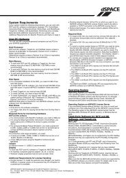
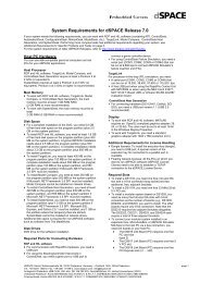
<strong>2004</strong>-<strong>01</strong>-<strong>1240</strong><strong>An</strong> <strong>Overview</strong> <strong>of</strong> <strong>Hardware</strong>-<strong>In</strong>-<strong>the</strong>-<strong>Loop</strong> TestingSystems at VisteonSyed Nabi and Mahesh BalikeVisteon CorporationJace Allen and Kevin Rzemien<strong>dSPACE</strong> <strong>In</strong>c.Copyright © <strong>2004</strong> SAE <strong>In</strong>ternationalABSTRACTThis paper discusses our experiences on <strong>the</strong>implementation and benefits <strong>of</strong> using <strong>the</strong> <strong>Hardware</strong>-<strong>In</strong><strong>the</strong>-<strong>Loop</strong>(HIL) systems for Powertrain control systems<strong>of</strong>tware verification and validation. The Visteon HILsystem integrated with several <strong>of</strong>f-<strong>the</strong>-shelf diagnosticsand calibration tools is briefly explained. Fur<strong>the</strong>r,discussions on test automation sequence control andfailure insertion are outlined The capabilities andadvantages <strong>of</strong> using HIL for unit level s<strong>of</strong>tware testing,open loop and closed-loop system testing, fault insertionand test automation are described. HIL also facilitatesS<strong>of</strong>tware and <strong>Hardware</strong> <strong>In</strong>terface validation testing withlow-level driver and platform s<strong>of</strong>tware. This paperattempts to show <strong>the</strong> experiences with and capabilities<strong>of</strong> <strong>the</strong>se HIL systems.and cost involved with <strong>the</strong> testing <strong>of</strong> complex electronicand component systems forced <strong>the</strong> automotive industryto investigate and invest in better testing methodologies.The advancement <strong>of</strong> computer technology, availability <strong>of</strong>highly efficient low cost compute engines and, readilyavailable <strong>of</strong>f-<strong>the</strong>-shelf systems, have pushed <strong>the</strong> viabilityand usability <strong>of</strong> <strong>the</strong> HIL technology from <strong>the</strong> Defenseand Aerospace industry to <strong>the</strong> Automotive industry.After <strong>the</strong> successful use <strong>of</strong> HIL simulation technologiesin <strong>the</strong> Aerospace industry, <strong>the</strong> Automotive industryadopted <strong>the</strong> technique in <strong>the</strong> 1990s. Several successfulpartial and complete closed loop simulations can becited in <strong>the</strong> literature since <strong>the</strong>n [1,2].INTRODUCTIONHIL technology has been in wide use in Defense andAerospace industry as early as <strong>the</strong> 1950s. <strong>In</strong> spite <strong>of</strong> <strong>the</strong>high cost <strong>of</strong> <strong>the</strong> HIL technology in those days, <strong>the</strong>Defense and Aerospace industry took advantage <strong>of</strong> HILsystems mainly due to <strong>the</strong> risk <strong>of</strong> human life involved in<strong>the</strong> real time system and <strong>the</strong> extremely expensiveprototype systems under test. The automotive industrydid not embrace HIL technology for development andtesting <strong>of</strong> automotive control systems mainly due to itshigh cost and feasibility <strong>of</strong> using <strong>the</strong> HIL technology forcomparatively simpler control systems.Over <strong>the</strong> years, <strong>the</strong> automotive industry started addingmore and more diverse embedded s<strong>of</strong>tware controlledelectronic components in vehicles to improveperformance; efficiency and comfort as well as to becompliant with government regulated and mandatedemission requirements. The pressure <strong>of</strong> increasedcomplexity in <strong>the</strong> design and verification process timingFigure 1 Traditional Development ProcessThe traditional design, development and verificationprocess <strong>of</strong> automotive embedded control systems<strong>of</strong>tware comprises several steps and iterations asdepicted in Figure 1. As illustrated in <strong>the</strong> figure, during<strong>the</strong> design and verification process <strong>the</strong> designrequirements may change due to internal process,
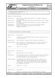
addition <strong>of</strong> new requirement, and refinement <strong>of</strong>requirement. The late changes in requirements cause asignificant impact on <strong>the</strong> development and testing time<strong>of</strong> control system s<strong>of</strong>tware and this iterative loop <strong>of</strong>requirement change, development and testing is notvery efficient. Fur<strong>the</strong>r, obtaining a prototype vehicleduring <strong>the</strong> early s<strong>of</strong>tware developmental phase isextremely difficult and cost prohibitive, especially for anon-OEM (Original Equipment Manufacturer)companies.A Powertrain Control Module (PCM) is one <strong>of</strong> <strong>the</strong> mostcomplex electronic embedded control systems in <strong>the</strong>modern vehicle. The PCM s<strong>of</strong>tware <strong>the</strong>refore requires arigorous and through testing <strong>of</strong> its functionality. <strong>In</strong> orderto manage <strong>the</strong> increasing demand <strong>of</strong> technology in PCMdesign, Visteon Corporation started investigating <strong>the</strong>possibilities <strong>of</strong> using a state-<strong>of</strong>-<strong>the</strong>-art HIL system forPCM s<strong>of</strong>tware development and verification in 1998. HILtechnology is best suited to perform a complete andrigorous testing <strong>of</strong> <strong>the</strong> Embedded control systems<strong>of</strong>tware <strong>of</strong> PCM. Visteon anticipated that HILsimulation would improve quality and also reducedevelopment time and cost. At <strong>the</strong> same time <strong>the</strong> HILsystem based development and testing will complement<strong>the</strong> implementation <strong>of</strong> model based s<strong>of</strong>twaredevelopment (MBD) technology. The initial strategy wasto implement HIL for PCM s<strong>of</strong>tware testing only.However, over time it became apparent that <strong>the</strong> sameimplementation could be easily tailored for <strong>the</strong>S<strong>of</strong>tware/<strong>Hardware</strong> <strong>In</strong>terface validation as well.Implementation <strong>of</strong> a HIL system for testing during <strong>the</strong>development phase <strong>of</strong> PCM s<strong>of</strong>tware also addresseso<strong>the</strong>r issues associated with <strong>the</strong> traditional bench testenvironment. Some <strong>of</strong> <strong>the</strong> issues associated with <strong>the</strong>traditional bench test environment are uncontrolled andnon-repeatable tests without proper closed loopfeedback to perform a complete system verification andvalidation <strong>of</strong> <strong>the</strong> s<strong>of</strong>tware in real time, difficulty inachieving consistency, manual mode <strong>of</strong> operation for setpoints, ad hock data capture and test results and <strong>the</strong>near impossible task <strong>of</strong> testing <strong>the</strong> complex closed loopcontrol algorithms <strong>of</strong> <strong>the</strong> PCM s<strong>of</strong>tware in an open loopbench test environment.Visteon has proven that <strong>the</strong>re are significant benefits <strong>of</strong>Open <strong>Loop</strong> HIL testing during <strong>the</strong> initial phase <strong>of</strong>s<strong>of</strong>tware development by performing unit level s<strong>of</strong>twareverification. HIL testing is also used for verification <strong>of</strong><strong>the</strong> S<strong>of</strong>tware and <strong>Hardware</strong> <strong>In</strong>terface <strong>of</strong> <strong>the</strong> low-levelplatform s<strong>of</strong>tware. The integration <strong>of</strong> HIL systems withcalibration and diagnostic tools also provides significantadvantages with closed loop simulation and testing <strong>of</strong>completely integrated s<strong>of</strong>tware in real time on <strong>the</strong> bench.Several o<strong>the</strong>r features <strong>of</strong> HIL such as test automation,test stimulus generation, and fault-insertion testing areaddressed. These HIL systems use Python, anadvanced test scripting language, to control testsequences and coordinate <strong>the</strong> variety <strong>of</strong> interfacesnecessary for a particular test, or a set <strong>of</strong> tests. Thistest-scripting feature <strong>of</strong> <strong>the</strong> HIL system gives <strong>the</strong> testdeveloper <strong>the</strong> capability to implement full lights-outtesting scenarios and also allow for exact reproductionfor subsequent DUT (Device Under Test) regressiontesting. The HIL systems also have <strong>the</strong> capability toinject stimulus signals into <strong>the</strong> DUT, which can be usedfor a variety <strong>of</strong> purposes. These include drive cycles foran engine or vehicle test, and also response datahistories for component validation.Finally, <strong>the</strong> interfaces between <strong>the</strong> PCM and <strong>the</strong> plant(Vehicle, Engine, etc) need to be tested. When failuresoccur with sensors or actuators, <strong>the</strong> PCM generallyneeds to detect <strong>the</strong>se and provide for strategies toovercome <strong>the</strong>m. Using <strong>the</strong> HIL systems, it is fullypossible to simulate almost any type <strong>of</strong> failure that acontroller could experience. This failure testing can alsobe performed during critical control periods, which mightnot be possible to implement on <strong>the</strong> actual target plant.Figure 2 Visteon HIL ArchitectureVISTEON HIL SYSTEMARCHITECTUREThe Visteon HIL s<strong>of</strong>tware-testing environment is built onmodified <strong>dSPACE</strong> midsize and/or full size enginesimulators integrated with several <strong>of</strong>f <strong>the</strong> shelf tools. Thesystem architecture <strong>of</strong> <strong>the</strong> Visteon HIL system is shownin block diagram in Figure 2. The Visteon HIL simulatoris housed inside a 19” desktop rack containing a PowerPC processor board for real time computation, aspecialized automotive HIL I/O board, additional I/Ocards, required signal conditioning boards, load boardswith fault simulation capability as <strong>the</strong> main component <strong>of</strong><strong>the</strong> simulator. The system is also equipped with a
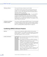
emote control power supply. The power supply can becontrolled in real time during simulation, which provides<strong>the</strong> capability <strong>of</strong> vehicle battery simulation The PCM isphysically connected to <strong>the</strong> HIL simulator by customizedharnesses for I/O routing ei<strong>the</strong>r directly or throughswitchable breakout boxes. Fur<strong>the</strong>r, it is possible toattach actual physical component assemblies to <strong>the</strong> HILsystem using an external interface. The system alsoaccommodates integration <strong>of</strong> <strong>of</strong>f-<strong>the</strong>-shelf calibrationand diagnostic tools. The integration <strong>of</strong> calibration anddiagnostic tools with <strong>the</strong> HIL system provides <strong>the</strong>capability <strong>of</strong> automated testing <strong>of</strong> very complexPowertrain control system s<strong>of</strong>tware. [3]One <strong>of</strong> <strong>the</strong> critical parts <strong>of</strong> this HIL system is <strong>the</strong> loadsubsystem. It is very critical to have an appropriate loadfor <strong>the</strong> actuator signals in order for <strong>the</strong> PCM s<strong>of</strong>tware towork properly. <strong>In</strong> order to accommodate <strong>the</strong> specialcharacteristics <strong>of</strong> certain actuators <strong>the</strong> system connectsto a specially designed company proprietary loadsubsystem. The closed loop simulation <strong>of</strong> <strong>the</strong> systemrequires appropriate feedback response from <strong>the</strong>actuator load to satisfy <strong>the</strong> smart device driver integratedcircuits (IC) and advanced On Board Diagnostics (OBD)system s<strong>of</strong>tware. Without <strong>the</strong> appropriate closed loopsystem and actuator load feedback, <strong>the</strong> PCM controllerwill enter a fault mode and will defeat <strong>the</strong> purpose <strong>of</strong>validation <strong>of</strong> <strong>the</strong> system s<strong>of</strong>tware. For <strong>the</strong> completeclosed loop system simulation ano<strong>the</strong>r significationrequirement is <strong>the</strong> representative plant model. The plantmodel should represent <strong>the</strong> physical behavior <strong>of</strong> <strong>the</strong>plant; in our implementation <strong>the</strong> plant consists <strong>of</strong> <strong>the</strong>engine, <strong>the</strong> transmission and o<strong>the</strong>r ancillarycomponents.interfaces. Refer to Figure 3 to see a depiction <strong>of</strong> some<strong>of</strong> <strong>the</strong>se interfaces. Below is a list <strong>of</strong> just some <strong>of</strong> <strong>the</strong>phases required to perform HIL testing:• Control <strong>of</strong> <strong>the</strong> test sequence to run and ability toregressively test• <strong>In</strong>jection <strong>of</strong> test stimulus in real-time• Access to <strong>the</strong> model parameters and data andcontrol <strong>of</strong> <strong>the</strong> simulation state• Access to external devices (Testers, Voltmeters,etc.)• Access to and control <strong>of</strong> PCM interfaces (diagnostictools)• Ability to generate test documentation and save testdata• Test data analysis during <strong>the</strong> testThe system chosen to perform <strong>the</strong> testing must provide<strong>the</strong> power to perform <strong>the</strong> above tasks, yet needs to berelatively easy to use in order to minimize testdevelopment costs and allow for changes in <strong>the</strong> testingprocess. The system chosen by Visteon is <strong>the</strong> s<strong>of</strong>twaretool ControlDesk ®2 , by <strong>dSPACE</strong>. ControlDesk providesall <strong>of</strong> <strong>the</strong> capabilities needed for a HIL test system,including hardware/model management, data acquisitionand graphical user-interface capabilities. The TestAutomation extension <strong>of</strong> ControlDesk is based on <strong>the</strong>python language, and it provides <strong>the</strong> interface librariesneeded to automate <strong>the</strong> tools and programs needed toperform <strong>the</strong> above listed tasks.A set <strong>of</strong> plant models suitable for real-time simulationhas been developed and validated in-house, torepresent various automotive subsystems for differentpowertrain applications. The real time executable plantmodels are developed in MATLAB ® , Simulink ®andStateflow ®1 , and are composed <strong>of</strong> flexible andconfigurable component and sub component models.Physical component and systems are represented inma<strong>the</strong>matical models. These representative plantmodels are developed with significant and adequatedetail to perform <strong>the</strong> controller s<strong>of</strong>tware algorithmverification and validation.TEST AUTOMATION SEQUENCE CONTROL ANDDESIGNPhases <strong>of</strong> testing and automationThe task <strong>of</strong> powertrain hardware and s<strong>of</strong>tware testingusing HIL simulation requires many phases andFigure 3 <strong>In</strong>terfaces in HIL SystemTest sequences and scripting with pythonPython is an open source language, available on <strong>the</strong>www.python.org website. It is an extremely powerful,1MATLAB, Simulink and Stateflow are trademarks <strong>of</strong> The MathWorks,<strong>In</strong>c.2ControlDesk is trademark <strong>of</strong> <strong>dSPACE</strong> GmbH.
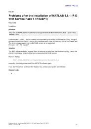
object-oriented language with programming syntax andusage very similar to Basic. It has been said that pythoncan speed up development by a factor <strong>of</strong> 10 over o<strong>the</strong>rprogramming languages, such as C [4]. Pythonprovides all <strong>of</strong> <strong>the</strong> control constructs and modularprogramming functionality needed for <strong>the</strong> developmentand maintenance <strong>of</strong> complex test sequences. TheControlDesk s<strong>of</strong>tware has an integrated pythoninterpreter and a function selector tool, to make pythondevelopment as easy as possible for <strong>the</strong> user. Testscripts can be run directly, or <strong>the</strong>y can also beconnected to events, including GUI events such asCommand buttons. Visteon has been able to programvery complex test sequences and make <strong>the</strong>m functionalin very short periods <strong>of</strong> time.Test stimulus generationControlDesk also provides mechanisms to assist in <strong>the</strong>generation <strong>of</strong> test stimuli (data streams) for specific testruns. The test stimulus is generated through python,using a library designed to generate <strong>the</strong> stimuli. <strong>In</strong> orderto generate this data in real-time, s<strong>of</strong>tware and hardwaremechanisms have been built into ControlDesk and <strong>the</strong><strong>dSPACE</strong> hardware, which allows for full fidelity <strong>of</strong>stimulus generation, with time based events guaranteedto occur during testing. A sequence generator tool isincluded with ControlDesk, which allows for interactivegraphical user design <strong>of</strong> test stimuli. The sequencegenerator is based on time tags and specific functiontypes, which can be combined in different manners.There are also control constructs, which allow for easylooping and conditional execution <strong>of</strong> <strong>the</strong> data streams.The tool also assists <strong>the</strong> user by providing a pregeneration<strong>of</strong> <strong>the</strong> data, for verification prior to <strong>the</strong> test,and <strong>the</strong>n it provides <strong>the</strong> functions to allow <strong>the</strong> user tomap <strong>the</strong> data to model variables and execute <strong>the</strong>stimulus both interactively and within test sequences.<strong>An</strong>o<strong>the</strong>r feature <strong>of</strong> <strong>the</strong> Sequence generator is <strong>the</strong>capability to playback recorded data streams, capturedduring ei<strong>the</strong>r simulations or actual test runs. Thiscapability has been used very effectively by Visteon tosimulate drive cycles and control specific testsequences. <strong>An</strong>y data waveform stored in a predesignedMAT file format can be used for this purpose.The <strong>dSPACE</strong> hardware and s<strong>of</strong>tware systems provide<strong>the</strong> automatic buffering and interpolation processes thatallow for real-time data playback during simulation runs.Using test stimulus to control test execution is anexample <strong>of</strong> a data-driven system. This has manyadvantages over a model driven system, in that changesin <strong>the</strong> data streams do not require model changes andprovide greater flexibility in <strong>the</strong> modeling process. Themodels are simpler to design with less real-timeoverhead, and this also allows for using <strong>the</strong> samemodels for both <strong>of</strong>fline simulation and real-time testing.Advanced test scripting capabilitiesControlDesk Test Automation provides libraries <strong>of</strong>functions for controlling <strong>the</strong> user interface andControlDesk environment. It also has a MacroRecorder, which gives <strong>the</strong> user an easy method forcapturing testing sequences performed through <strong>the</strong> GUI.The Macro Recorder saves <strong>the</strong>se captured sequencesas python scripts, which can <strong>the</strong>n be easily replayed andalso modified to extend and augment <strong>the</strong>ir functionality.There are interface libraries for communicationprotocols, such as RS-232 and GPIB, which allow forinterfacing to external devices and systems. Librariesare also provided to allow for report generation and datacapture into several windows COM OLE programs, suchas Word and Excel. Finally, sets <strong>of</strong> functions areincluded which allow <strong>the</strong> user to access and controldiagnostic devices and calibration tools, using ei<strong>the</strong>rstandard protocols or <strong>the</strong> ASAP/MCD standards [3].Future pathPython is an extremely powerful tool and can be used todo every one <strong>of</strong> <strong>the</strong> tasks required for test automation.Visteon has had a successful experience with <strong>the</strong> use <strong>of</strong>test automation because <strong>of</strong> this. The next step in <strong>the</strong>future involves using a new 4GL testing system from<strong>dSPACE</strong>, called AutomationDesk, which is based ongraphically designing test sequences. The system is stillbased on python, but it eases <strong>the</strong> development andmaintenance process by providing a more intuitivegraphical design environment, as opposed to writingcode scripts. It is not a code generator, but insteadgenerates testing process objects from clearly definedtest system classes. AutomationDesk also provides avery powerful test management functionality, whichallows for more robust management <strong>of</strong> all <strong>of</strong> <strong>the</strong> facets<strong>of</strong> a test. These include <strong>the</strong> scripts, models, test data,test results, stimulus and parameter data, etc. [5].FAILURE INSERTION AND CLOSING THE LOOPGeneral overview<strong>In</strong> order to fully test a PCM, <strong>the</strong> PCM must be connectedto hardware interfaces that simulate <strong>the</strong> real plantenvironment as closely as possible. The PCM isgenerally designed to test <strong>the</strong>se interfaces for anyfailures, such as short circuits, missing sensors, etc, atwhich time <strong>the</strong> PCM will store a diagnostic code in itsmemory. A large percentage <strong>of</strong> <strong>the</strong> actual code in aproduction PCM is for diagnostics. If one <strong>of</strong> <strong>the</strong>sefailures occurs, <strong>the</strong> PCM s<strong>of</strong>tware is designed to recoverfrom this failure and ensure <strong>the</strong> safety <strong>of</strong> <strong>the</strong> passengersand <strong>the</strong> environment. The <strong>dSPACE</strong> HIL systemprovides a configurable set <strong>of</strong> relays in a Failure<strong>In</strong>sertion Unit (FIU), which can be commanded tosimulate <strong>the</strong>se failures. A failure for a PCM input cangenerally be simulated in s<strong>of</strong>tware and standardhardware. By sending a 0, 5 or vehicle battery voltage
input from simulated sensor different types <strong>of</strong> sensorfailure can be simulated. To simulate failures for PCMoutputs, however, this involves using electronic relays toprovide open circuits, short circuits to battery voltage orground, or even pin-to-pin short circuits. <strong>In</strong> addition,PCM outputs generally expect to have a specific loadattached, and failures are triggered if this is not <strong>the</strong> case.process [6]. This allows for <strong>the</strong> following standard testsequence:1. Place PCM in desired performance state2. <strong>In</strong>ject a failure3. Evaluate <strong>the</strong> PCM performance during <strong>the</strong> faultcondition4. Debrief <strong>the</strong> diagnostics tool to determine if <strong>the</strong> faultwas properly detected5. Reset <strong>the</strong> fault codes to allow for fur<strong>the</strong>r testingThe above test sequence is fully repeatable and byusing it, full lights-out testing sequences are possible.All <strong>of</strong> <strong>the</strong> diagnostic codes for a PCM may be evaluatedin a single test run (with a combination <strong>of</strong> sequences)and a complete test report will be automaticallygenerated to record <strong>the</strong> results. Once this process isimplemented, <strong>the</strong> daunting task <strong>of</strong> test regression foriterative s<strong>of</strong>tware releases is easily contained.BENEFITS – HIL IN EVERY DEVELOPMENTALPHASEFigure 4 Failure <strong>In</strong>sertion Unit Block DiagramTest scripting interfaceThe control <strong>of</strong> <strong>the</strong> FIU system is done using a pythonlibrary in <strong>the</strong> test automation environment. A PCMoutput channel is wired to a HIL load interface, but first itis routed through a FIU channel (See Figure 4). Thisallows for exposing <strong>the</strong> channel to <strong>the</strong> failures neededfor testing. The <strong>dSPACE</strong> FIU interface is based on aserial communications protocol, which can becommanded directly from <strong>the</strong> Host PC. Simple functioncalls are used in order to control a particular FIUchannel, which eliminates <strong>the</strong> need for <strong>the</strong> user to learn<strong>the</strong> details <strong>of</strong> <strong>the</strong> FIU serial communication protocol.With our experience during <strong>the</strong> developmental andimplementation stages <strong>of</strong> <strong>the</strong> HIL systems we foundseveral advantages <strong>of</strong> using HIL systems in testing andvalidating our s<strong>of</strong>tware product. Although, <strong>the</strong> initialscope for using <strong>the</strong> HIL system was limited, we now use<strong>the</strong> system in every phase <strong>of</strong> <strong>the</strong> PCM s<strong>of</strong>twaredevelopment process. Figure 5 illustrates <strong>the</strong> SystemEngineering V with <strong>the</strong> phases <strong>of</strong> s<strong>of</strong>tware developmentand highlights how HIL is being used in every stage <strong>of</strong><strong>the</strong> s<strong>of</strong>tware development.<strong>In</strong>tegration <strong>of</strong> diagnostic tools for closed loop testingIt is sometimes enough to simulate failures duringtesting only for <strong>the</strong> analysis <strong>of</strong> <strong>the</strong> effects on systemperformance. However, in order to fully read systemdiagnostics and also reset <strong>the</strong> error conditions, it isnecessary to connect a diagnostic tester/device. Thisdevice is used to debrief <strong>the</strong> error codes registered in<strong>the</strong> PCM following any diagnostic error and report <strong>the</strong>secodes back to <strong>the</strong> tester. The python test automationlibraries also include functions to interface to and control<strong>the</strong>se diagnostic devices. These testers generally use astandard serial or CAN-based protocol for interfacing to<strong>the</strong> PCM. O<strong>the</strong>rs utilize <strong>the</strong> ASAM/MCD standard forexternal operation <strong>of</strong> <strong>the</strong> device. By providing <strong>the</strong>capabilities for controlling <strong>the</strong>se diagnostic tools,ControlDesk can fully close <strong>the</strong> loop on <strong>the</strong> testingFigure 5 HIL used in every step <strong>of</strong> developmentcycle.Broadly, <strong>the</strong> HIL applications for PCM testing in <strong>the</strong>design phase can be classified as Open <strong>Loop</strong> Testing(OLT) and Closed-<strong>Loop</strong> Testing (CLT). <strong>In</strong> <strong>the</strong> OLT a
simpler I/O model is used with no feedback from <strong>the</strong>plant model, as shown in Figure 6. <strong>In</strong> <strong>the</strong> OLT <strong>the</strong> inputsare not dependant <strong>of</strong> <strong>the</strong> outputs <strong>of</strong> <strong>the</strong> system. Theyare independent <strong>of</strong> each o<strong>the</strong>r, and consequentially <strong>the</strong>dynamic behavior <strong>of</strong> <strong>the</strong> system cannot be tested inOLT. <strong>In</strong> OLT a set <strong>of</strong> values for inputs are provided to<strong>the</strong> system and <strong>the</strong> output responses <strong>of</strong> <strong>the</strong> systems aremonitored and recorded.vehicle speed is monitored and <strong>the</strong> throttle and brakecommand are changed manually or using an automaticdriver controller model. Closed loop simulation is wellsuited for system level testing and verification. <strong>In</strong> <strong>the</strong>following sections <strong>the</strong>se applications <strong>of</strong> HIL arediscussed in detail.EXECUTABLE I/O TESTING USING OLTImplementationDevelopment <strong>of</strong> Low-Level <strong>In</strong>put/Output Driver (LLD)s<strong>of</strong>tware is one <strong>of</strong> <strong>the</strong> early phases <strong>of</strong> PCM s<strong>of</strong>twaredevelopment. The LLD is implemented on top <strong>of</strong> <strong>the</strong>Real Time Operating System (RTOS). The LLD s<strong>of</strong>twareis <strong>the</strong> interface between <strong>the</strong> PCM <strong>Hardware</strong> and/or HighLevel Driver S<strong>of</strong>tware and/or <strong>the</strong> application s<strong>of</strong>tware.The LLD s<strong>of</strong>tware is a fundamental piece <strong>of</strong> s<strong>of</strong>tware inorder for <strong>the</strong> PCM application s<strong>of</strong>tware to work properlywith <strong>the</strong> system hardware.Figure 6 Open <strong>Loop</strong> Testing in HIL<strong>In</strong> OLT <strong>the</strong> performance <strong>of</strong> <strong>the</strong> system s<strong>of</strong>tware,actuators commands or outputs from <strong>the</strong> PCM aremonitored and verified, while feeding a predefined set <strong>of</strong>values <strong>of</strong> sensor data to <strong>the</strong> PCM. OLT is applicable tocheck <strong>the</strong> PCM I/O, low-level drivers, unit testing andsome integration testing. On <strong>the</strong> o<strong>the</strong>r hand, <strong>the</strong> CLTrequires a complete plant model with appropriatefeedback response for <strong>the</strong> system as shown in Figure 7.<strong>In</strong> a CLT environment <strong>the</strong> PCM commanded values areused to run <strong>the</strong> actuator plant models. The actuator plantmodel output is in mechanical or electrical units and isfur<strong>the</strong>r used in <strong>the</strong> plant model to compute <strong>the</strong> plantbehavior and dynamic sensor responses.Figure 7 Closed <strong>Loop</strong> Testing in HIL<strong>In</strong> <strong>the</strong> CLT environment <strong>the</strong> controller feedback loop ispreserved, and thus a complete system verification andvalidation is possible in this environment. A simple drivermodel is used to drive <strong>the</strong> vehicle simulation whereTraditionally, testing <strong>of</strong> <strong>the</strong> LLD s<strong>of</strong>tware is done on whatis referred to as a static test bench. The input to <strong>the</strong>hardware is provided from a power supply and/or asignal generator and <strong>the</strong> outputs <strong>of</strong> <strong>the</strong> hardware aremonitored with a chart recorder and/or an oscilloscope.<strong>An</strong> early phase <strong>of</strong> automated testing <strong>of</strong> LLD s<strong>of</strong>twarewas implemented by a skeleton executable s<strong>of</strong>twarelayer developed on top <strong>of</strong> <strong>the</strong> LLD s<strong>of</strong>tware layer; henceit is called <strong>the</strong> “Executable I/O (EIO) s<strong>of</strong>tware”.The different layers <strong>of</strong> <strong>the</strong> EIO s<strong>of</strong>tware and <strong>the</strong> HILsystem interface block diagram are illustrated in Figure8. The executable layer is implemented in two levelstructures, <strong>the</strong> first is <strong>the</strong> communication layer and o<strong>the</strong>ris <strong>the</strong> command layer. The communication layerinterfaces with <strong>the</strong> user and <strong>the</strong> command layerexercises <strong>the</strong> LLD s<strong>of</strong>tware to manipulate <strong>the</strong> hardwareI/O. The communication layer <strong>of</strong> <strong>the</strong> EIO s<strong>of</strong>tware isintegrated with <strong>the</strong> HIL communication layer, and <strong>the</strong>HIL becomes <strong>the</strong> server and <strong>the</strong> EIO s<strong>of</strong>tware becomes<strong>the</strong> client. A sequence <strong>of</strong> tests is developed to exercise<strong>the</strong> complete range <strong>of</strong> all I/O. The HIL system <strong>In</strong>putdrivers command <strong>the</strong> EIO s<strong>of</strong>tware to provide acomplete range <strong>of</strong> valid as well as invalid values tooutput drivers. The HIL system co-ordinates <strong>the</strong> dataplayback and data capture simultaneously to completelyautomate testing <strong>of</strong> LLD s<strong>of</strong>tware. This EIO s<strong>of</strong>twareimplementation provided <strong>the</strong> capability <strong>of</strong> testing <strong>the</strong> LLDs<strong>of</strong>tware with test points over a range <strong>of</strong> <strong>the</strong> inputs andoutputs.Prior to <strong>the</strong> integration <strong>of</strong> HIL with <strong>the</strong> EIO testing, <strong>the</strong>manual mode <strong>of</strong> testing was only capable <strong>of</strong> using a verylimited set <strong>of</strong> data points, which was not exhaustingenough to completely test <strong>the</strong> entire range <strong>of</strong> <strong>the</strong>hardware I/O. This manual method <strong>of</strong> testing was shownto be both time consuming and error prone. Using HIL
technology for <strong>the</strong> EIO s<strong>of</strong>tware testing <strong>the</strong> complete I/Orange can be tested automatically.on a target. Utilization <strong>of</strong> test scripting and test stimulusgeneration technique <strong>the</strong> HIL system provided somelevel <strong>of</strong> dynamic input to <strong>the</strong> system, ra<strong>the</strong>r than just astatic set <strong>of</strong> input values.Figure 8 HIL integration <strong>of</strong> Executable I/O TestingThis implementation <strong>of</strong> HIL integrated EIO s<strong>of</strong>twaresignificantly reduced <strong>the</strong> testing time <strong>of</strong> all PCM I/Os,and provided a far more complete range <strong>of</strong> every test aswell. <strong>In</strong> later applications, using this testing very early in<strong>the</strong> development phase flagged some discrepanciesbetween <strong>the</strong> requirements, <strong>the</strong> specifications and <strong>the</strong>s<strong>of</strong>tware implementation. By discovering <strong>the</strong>sediscrepancies at this early phase, significant resourceswere saved, compared to finding <strong>the</strong>se discrepancieslater in <strong>the</strong> development cycle.UNIT LEVEL TESTING USING OLTThe next level <strong>of</strong> testing phase is Unit Level Testing(ULT) <strong>of</strong> application s<strong>of</strong>tware. ULT is a derivative <strong>of</strong>OLT. The Powertrain application s<strong>of</strong>tware consists <strong>of</strong>multiple interdependent features, and each featurecontains different level <strong>of</strong> sub-features. The featuresand sub-features <strong>of</strong> application s<strong>of</strong>tware are defined byfunctional boundaries. The features and sub-featuresare developed based on <strong>the</strong> Powertrain requirements.The features and sub-features are tested against suchdefined requirements. <strong>In</strong> ULT one piece or one unit <strong>of</strong>s<strong>of</strong>tware defined by certain functional boundaries istested. For ULT, sets <strong>of</strong> inputs are designed to exercise<strong>the</strong> specific unit <strong>of</strong> s<strong>of</strong>tware and fed into <strong>the</strong> PCM, and<strong>the</strong> output from that specific piece <strong>of</strong> s<strong>of</strong>tware ismonitored and recorded. The outputs <strong>of</strong> <strong>the</strong> s<strong>of</strong>twareare checked against <strong>the</strong> requirements for <strong>the</strong> s<strong>of</strong>twaregiven that set <strong>of</strong> inputs. Traditionally, <strong>the</strong> ULT is amanual operation using tools like a s<strong>of</strong>tware debuggerand manually stepping through s<strong>of</strong>tware code to check<strong>the</strong> values <strong>of</strong> <strong>the</strong> outputs <strong>of</strong> <strong>the</strong> s<strong>of</strong>tware, as well usingtools like an oscilloscopes and chart recorders to recordoutputs from <strong>the</strong> PCM. The HIL integration <strong>of</strong> <strong>the</strong> ULTprovided a more methodical way <strong>of</strong> completing unit testFigure 9 Open <strong>Loop</strong> PCM Application TestingINTEGRATION TESTING USING OLTOnce, sets <strong>of</strong> ULTs are completed, <strong>the</strong> next obviousstep is to recombine <strong>the</strong>se units and test on a subintegration level. The integration <strong>of</strong> features is testedusing <strong>the</strong> OLT methodology to test <strong>the</strong> interactionbetween several features. <strong>In</strong> <strong>the</strong> sub-integration level <strong>the</strong>complete s<strong>of</strong>tware is not integrated with all <strong>the</strong> requiredfeatures, but a few closely related features areintegrated as a broad feature. <strong>In</strong> this test environment<strong>the</strong> feature level inputs are provided from <strong>the</strong> HIL systemas dynamic inputs, and <strong>the</strong> outputs from <strong>the</strong> subintegrationlevel are monitored and recorded. Eventhough <strong>the</strong> input values may have some dynamicbehavior in it, <strong>the</strong> absence <strong>of</strong> dynamic plant modelprevented it from running in closed loop environment.The dynamic inputs were not based on <strong>the</strong> systemresponse output; ra<strong>the</strong>r it was a coherent set <strong>of</strong> inputdata. Refer to Figure 9 for a block diagram <strong>of</strong> open loopintegration testing. The next natural progression <strong>of</strong>testing is <strong>the</strong> verification <strong>of</strong> <strong>the</strong> complete feature inClosed <strong>Loop</strong>.PROGRESSION FROM OPEN LOOP VERIFICATIONTO CLOSED LOOP VERIFICATION<strong>In</strong> <strong>the</strong> OLT methodology <strong>of</strong> verification, <strong>the</strong> inputs to <strong>the</strong>PCM are provided during <strong>the</strong> simulation, and <strong>the</strong>actuator outputs from <strong>the</strong> PCM are monitored. Thecontrol loop feedback mechanism is not in place so <strong>the</strong>dynamic response <strong>of</strong> <strong>the</strong> PCM s<strong>of</strong>tware cannot be testedin OLT. CLT testing is necessary in order to fully validate<strong>the</strong> functionally <strong>of</strong> <strong>the</strong> PCM.
Figure 10 Closed <strong>Loop</strong> PCM Application Testing.Figure 11 Closed <strong>Loop</strong> Plant Model.SYSTEM LEVEL TESTING USING CLTThe components <strong>of</strong> system level testing using CLT areillustrated in Figure 10. The fundamental differencebetween <strong>the</strong> OLT and CLT is <strong>the</strong> presence <strong>of</strong> dynamicplant model in <strong>the</strong> CLT system running in real timesimulation. The plant models represent <strong>the</strong> bahavior <strong>of</strong><strong>the</strong> actual plant and provide appropriate feedbackresponse. The response <strong>of</strong> <strong>the</strong> plant model influences<strong>the</strong> input to <strong>the</strong> system, thus providing a completedynamic system simulation with controller feedback looppreserved. Figure 11 shows a block diagramrepresentation <strong>of</strong> Open and Closed loop testinginterfaces <strong>of</strong> <strong>the</strong> HIL system with <strong>the</strong> PCM. The“Ambient_and_Environment” block contains static inputssuch as atmospheric pressure and temperature; <strong>the</strong>“Driver_<strong>In</strong>puts” block contains a manual and automaticdriver model. The automatic driver model compares <strong>the</strong>vehicle speed feedback with <strong>the</strong> speed stimulus anddecides <strong>the</strong> required throttle and brake inputs to <strong>the</strong>plant model, while manual driver provides <strong>the</strong> hooks tocontrol <strong>the</strong> brake and throttle pedal input from externalsource under simulation environment.The “PCM_<strong>In</strong>terface” block contains <strong>the</strong> routing <strong>of</strong> I/Osignals between a specific family <strong>of</strong> PCM and <strong>the</strong> HILsystem hardware. The "Vehicle Model" contains <strong>the</strong>actual plant model representing <strong>the</strong> dynamic behavior <strong>of</strong><strong>the</strong> plant, for our application it is a combination <strong>of</strong> andengine and transmission model. We have implementeda complete set <strong>of</strong> sensors, actuators and plant models inthis system. <strong>In</strong> order to be able to simulate in real time,we used a regression based engine model, usingmapping data for <strong>the</strong> same engine from a Dynamometer.Simplified transmission, driveline and vehicle modelswere also implemented. After successful simulation <strong>of</strong>Key On Engine Off (KOEO) and Key On Engine Running(KOER) conditions, <strong>the</strong> system was successfully testedand simulated for idle conditions, followed by manualand automatic drive cycle simulation implementation.Prior to integration <strong>of</strong> <strong>the</strong> plant models with <strong>the</strong> HILsystems, <strong>the</strong> plant models were simulated and validatedon <strong>the</strong> desktop. After validation <strong>of</strong> <strong>the</strong> plant model in <strong>the</strong>desktop environment <strong>the</strong> models were integrated with<strong>the</strong> HIL system. <strong>In</strong> order to validate <strong>the</strong> plant models <strong>the</strong>results obtained from a real engine drive cycle testconducted on a Dynamometer were compared with <strong>the</strong>simulation results. <strong>In</strong> drive cycle exercise <strong>the</strong> vehicle isdriven through a known speed pr<strong>of</strong>ile (e.g. FTP UDDS).The target speed is input to <strong>the</strong> automatic driver model.The automatic driver receives <strong>the</strong> actual speed <strong>of</strong> <strong>the</strong>vehicle as a feed back from <strong>the</strong> complete vehicle plantmodel. The automatic driver manipulates <strong>the</strong> brake andthrottle to keep <strong>the</strong> vehicle in targeted speed. Thevehicle speed pr<strong>of</strong>ile from <strong>the</strong> Dynamometer test cellrecording (using calibration tool, ATI Vision 1.9) 3wasused as <strong>the</strong> input stimulus for <strong>the</strong> automatic driver for<strong>the</strong> simulation. Engine torque, engine speed and vehiclespeed from <strong>the</strong> simulation are recorded usingControlDesk, <strong>the</strong> HIL user interface s<strong>of</strong>tware, and <strong>the</strong>data was compared. The comparison (not presented inthis paper) <strong>of</strong> <strong>the</strong> vehicle and engine speed pr<strong>of</strong>ile andengine torque values along with o<strong>the</strong>r variables showeda very good correlation with minimal error. Themaximum errors in <strong>the</strong>se comparisons were less than 10percent. Although final s<strong>of</strong>tware verification andvalidation can be done only on a real vehicle, <strong>the</strong>complete closed loop simulation can easily be used forvalidating s<strong>of</strong>tware at a system level during <strong>the</strong> earlydesign stages <strong>of</strong> s<strong>of</strong>tware development with less than 10percent error margin to validate <strong>the</strong> PCM s<strong>of</strong>tware.There are certain limitations in using HIL for validationand verification <strong>of</strong> PCM s<strong>of</strong>tware due to high3ATI is trademark <strong>of</strong> Accurate Technologies <strong>In</strong>c.
computational requirements for a real-time simulation.For example <strong>the</strong> emission related testing and validationis not feasible in <strong>the</strong> current HIL environment. A betterplant model (e.g. complete detail combustion basedmodel), however, can provide better correlation <strong>of</strong>engine variables as well engine performance. However,a detailed combustion based model may not be suitablefor real time execution with <strong>the</strong> present computingtechnology.Future advancement, both in real-time computing andplant modeling will close this gap <strong>of</strong> complete bench topsimulation and may make <strong>the</strong> HIL an absolutereplacement for a real vehicle for s<strong>of</strong>tware validation andverification.CONCLUSIONA brief discussion <strong>of</strong> on <strong>the</strong> implementation and usagescenario <strong>of</strong> HIL systems at Visteon Corporation for PCMs<strong>of</strong>tware verification and validation is presented in thispaper. The Powertrain S<strong>of</strong>tware development group inVisteon uses HIL systems in every step <strong>of</strong> <strong>the</strong> s<strong>of</strong>twaredevelopmental phase.Using HIL in integrated EIO s<strong>of</strong>tware, Unit Testing, andclosed loop testing <strong>of</strong> <strong>the</strong> system s<strong>of</strong>tware significantlyreduced <strong>the</strong> testing time and improved s<strong>of</strong>tware quality.S<strong>of</strong>tware quality is improved by identifying potentialerrors and/or discrepancies between <strong>the</strong> requirement,specification and s<strong>of</strong>tware very early in <strong>the</strong> developmentphase.The successful implementation <strong>of</strong> closed loop simulationhas proved to be useful in validating several features at<strong>the</strong> system level. However, fur<strong>the</strong>r improvements in realtime computing technology and implementation will berequired for simulating features such as emissionrequirements.REFERENCES1. H. Hanselmann, "<strong>Hardware</strong>-in-<strong>the</strong>-<strong>Loop</strong> SimulationTesting and its <strong>In</strong>tegration into a CACSD Toolset",IEEE <strong>In</strong>ternational Symposium on Computer-AidedControl System Design 1996.2. Hanselmann, H.: Advances in Desktop <strong>Hardware</strong>-<strong>In</strong><strong>the</strong>-<strong>Loop</strong>Simulation. SAE Paper 970932, 1997.3. S. Nabi, "Development <strong>of</strong> an <strong>In</strong>tegrated TestEnvironment for ECU S<strong>of</strong>tware Validation," <strong>dSPACE</strong>User Conference 2002,4. Eckel, B.; "Design Patterns <strong>In</strong> Python", 2002S<strong>of</strong>tware Development West conference, San Jose,CA, USA.5. Lamberg, K.; Richert, J.; Rasche, R.; A NewEnvironment for <strong>In</strong>tegrated Development andManagement <strong>of</strong> ECU Tests, SAE 2003-<strong>01</strong>-1024,Detroit, USA.6. Gehring, J.; Schuette, H.; A <strong>Hardware</strong>-in-<strong>the</strong>-<strong>Loop</strong>Test Bench for <strong>the</strong> Validation <strong>of</strong> Complex ECUNetworks, SAE 2002-<strong>01</strong>-08<strong>01</strong>, Detroit, USACONTACTSyed NabiVisteon CorporationVisteon Technical Center17000 Rotunda Dr.Dearborn, MI 48121Phone: (313) 755-1881E-mail: snabi@visteon.comMahesh Balike, PhDVisteon CorporationVisteon Technical Center17000 Rotunda Dr.Dearborn, MI 48121Phone: (313) 755-3804E-mail: mbalike@visteon.comJace AllenSenior Project EngineerApplications Group<strong>dSPACE</strong>, <strong>In</strong>c.28700 Cabot DriveSuite 1100Novi, MI 48377Phone: (248) 567-1265Fax: (248) 567-<strong>01</strong>30E-mail: jallen@dspaceinc.comKevin RzemienSupervisorApplications Group<strong>dSPACE</strong>, <strong>In</strong>c.28700 Cabot DriveSuite 1100Novi, MI 48377Phone: (248) 567-1265Fax: (248) 567-<strong>01</strong>30E-mail: krzemien@dspaceinc.comADDITIONAL SOURCES1. R.W. Weeks and J.J. Moskwa, "Automotive EngineModeling for Real-Time Control UsingMATLAB/SIMULINK", SAE paper 950417.2. H. Hanselmann, "<strong>Hardware</strong>-in-<strong>the</strong>-<strong>Loop</strong> SimulationTesting and its <strong>In</strong>tegration into a CACSD Toolset",
IEEE <strong>In</strong>ternational Symposium on Computer-AidedControl System Design 1996.3. S. Raman, N. Sivashankar, W. Milam, W. Stuart andS. Nabi, "Design and implementation <strong>of</strong> HILsimulators for powertrain control system s<strong>of</strong>twaredevelopment," Proceedings <strong>of</strong> <strong>the</strong> American ControlConference, pp. 709-713, 1999.4. N. Sivashankar and K. Butts, "A ModelingEnvironment for Production Powertrain ControllerDevelopment," Proceedings <strong>of</strong> IEEE CCA/CACSD,session CACSD-563, 1999.DEFINITIONS, ACRONYMS, ABBREVIATIONSCANCLTController Area NetworkClosed <strong>Loop</strong> TestingDUT Device Under TestECU Engine Control UnitEIO Executable I/O S<strong>of</strong>twareFIU Fault <strong>In</strong>sertion UnitFTP Federal Test ProcedureHIL <strong>Hardware</strong>-<strong>In</strong>-The-<strong>Loop</strong>HW <strong>Hardware</strong>I/O <strong>In</strong>put/OutputLLD Low Level Driver S<strong>of</strong>twareMBD Model Based DevelopmentOBD On Board DiagnosticsOEM Original Equipment ManufacturerOLT Open <strong>Loop</strong> TestingPCM Powertrain Control ModuleRTOS Real Time Operating SystemUDDS Urban Dynamometer Driving ScheduleULT Unit Level Testing