CODE FILEBY LES STOCH, P.ENG.‘Tis the season for the reasonAgreat deal of wisdom supports the reason(s) for writingeach Rule of the Canadian <strong>Electrical</strong> Code (CEC);reasons that are not always clear to CEC users. In fact,we’re not always completely satisfied to follow the Ruleswithout first understanding the reasons behind them. Solet’s look at several Rules from Section 10, Grounding andBonding, and explore the reasons behind them.Rule 10-700(2)(a) specifies that a manufactured groundingelectrode may consist of at least two, 3-metre groundrods driven full-length into the earth, spaced at least 3 metresapart and bonded together. Obviously, achieving the lowestpossible (or, at least, acceptable) grounding resistance is theRule’s primary objective, but why a minimum of 3 metres?Let’s go to the beginning. The measured resistance ofany grounding electrode is the sum of all its resistancesincluding the grounding conductors and connections, thecontact resistance between the grounding electrode andthe earth, and the resistance of the earth. The first twoare extremely small; we can, as a rule, neglect them, andit’s customary to consider the resistance of the groundingelectrode to be the resistance of the earth.To better understand this concept, we can think of thesoil around each ground rod as a series of cylindrical shellsspaced equal distances apart around the rod. The cylindernearest to and around the ground rod will have the highestresistance, since it has the smallest cross-sectional areaand volume. As we move further away from the rod, eachsubsequent cylinder will have a progressively larger volumeand, therefore, a lower resistance across it.In practice, if we took a number of grounding resistancemeasurements at several distances from a single groundrod, we would find that about 25% of the total groundingresistance appears at 0.03 metres from the rod, 52% at 0.15metres and 94% at 3 metres. In fact, we can only measure100% of the total grounding resistance at an approximatedistance of 7.6 metres to the rod.Since most of the grounding resistance is nearest tothe rod, we can conclude without difficulty that spacingground rods closely together will not greatly improve theoverall grounding resistance provided by a single rod.When the rods are spaced closely together, overlappingcurrent dissipation from the ground rods during a faultincreases their voltages and the overall grounding resistance.As the rule prescribes, we need to install ground rodsat least 3 metres apart so as to effectively reduce the overallresistance of our grounding electrode.Rule 10-806(4) requires that magnetic materials usedto enclose grounding conductors must be bonded to thegrounding conductors at each end. When a sleeve of iron orsteel is used for mechanical protection, it amplifies the magneticfield around the conductor during current flow, increasingthe voltage drop and impedance across the conductor.How does bonding help? To reduce the inductive reactancedue to the magnetic field, both ends of the sleevemust be bonded to the conductor so that the metal sleevecan carry a portion of the ground fault current, and toavoid an increase in the voltage drop and impedance in theconductor. (This preventive measure is not required whenusing non-magnetic sleeves for mechanical protection.)According to Rule 10-700(3)(a), a field-assembledgrounding electrode may consist of a copper conductorat least 3-metres long, sized in accordance with Table 43,enclosed in the bottom 50 mm of a concrete foundationfooting and at least 600 mm below grade.How does enclosing a conductor in concrete providean effective grounding electrode? Concrete located belowgrade has a somewhat lower resistivity than average loamsoil. For this reason, encasement of a wire in concrete willresult in lower resistance in earth of average or high resistivity.This is due to the reduction of grounding resistanceclosest to the electrode. (From our earlier discussion wealready know that most of the overall grounding resistancewill be found nearest the copper conductor.)Rule 10-702 specifies that, where there are multiplegrounding systems for electrical, communications, CATVand lightning protection systems, they must be separatedat least 2 metres from each other and bonded together bya minimum #6 AWG copper conductor. In the case oflighting protection, bonding between systems must be ator below grade.What are the advantages of this rule? Separation andbonding are both required because a ground fault couldoccur on any of the systems; this ensures a low impedancefault path to clear faults on any of the systems as quicklyas possible. Bonding between grounding systems is alsorequired so that, in the event of a lightning strike on anyof the systems, damage may be avoided from side flashesbetween the grounding systems.Les Stoch, P.Eng., is president of L. Stoch & Associates, specialistsin quality management/engineering services. He is a member ofPEO, OEL and IAEI, and develops and delivers electrical code andtechnical workshops for Dalhousie University. He also developedthe Master Electrician training program and Exam (Ontario) for the<strong>Electrical</strong> Contractor Registration Agency. Visit him online at www.lstoch.com.Questions and answerscompiled by ESATackle theCode Conundrum...if you dareSo, you think you know the electrical code, eh? Well, we’ll soonfind out if you’re an electrical code junkie or downright codeclueless.Take a look at the following questions and check youranswers in February’s <strong>Electrical</strong> <strong>Business</strong>.How did you do?3 of 3 – Not only are you smart, you love to show off.1 of 3 – Your understanding of these questions is not up to code.2 of 3 – You’re pretty smart, but you still missed one.0 of 3 – Did you come up with your answers by playing Eenie,Meenie, Minie, Moe?Question 1Voltage applied to piping for pipeline resistanceheating shall not exceed 120V, and the supply shallbe from an auto-transformer.a) True b) FalseQuestion 2A garage that is part of a bulk storage plant—inwhich tank vehicles are stored or repaired—shallbe considered to be a Class I, Zone 2 location up to___ mm above floor or grade level (unless conditionswarrant more severe classification or a greater extentof the hazardous area).a) 50 mm c) 300 mmb) 150 mm d) 450 mmQuestion 3Tap connection conductors for a field-wired recessedluminaire shall be installed in a raceway extendingat least 300 mm, but not more than 2 m, from theluminaire and terminated in an outlet box.a) True b) FalseAnswersto Code Conundrum▼▼▼<strong>Electrical</strong> <strong>Business</strong> November/December 2007Q-1: Non-current-carrying parts of tube stands, tables and otherapparatus in an installation of diagnostic imaging installationsshall not be bonded to ground.False. Rule 52-014 states: “Non-current-carrying parts of tubestands, tables, and other apparatus shall be bonded to ground inconformity with the requirements of Section 10”.Q-2: All metal raceways and all non-current-carrying metal portionsof fixed or portable equipment used in finishing processes—regardless of voltage—shall be bonded to ground in accordance withSection 10.True. Rule 20-414.Q-3: 35 (1-1/4) rigid PVC conduit shall be securely attached to hangersor to a solid surface with the maximum spacing of the points ofsupports not greater than:1.2 m. Rule 12-1114(1)(b), which refers to the maximum spacingof conduit supports: (1) “All rigid PVC and HFT conduit of one sizeshall be securely attached to hangers or to a solid surface with themaximum spacing of the points of supports not greater than: (b) 1.2m for 35 (1-1/4) and 41 (1-1/2) trade size conduit”.To find out more, register to receive CSA’s “Keep Me Informed” e-newsletterCSA_banner_EB_Nov07.indd 126 • JANUARY 2008 • www. mag.com11/23/07 12:06:47 PM
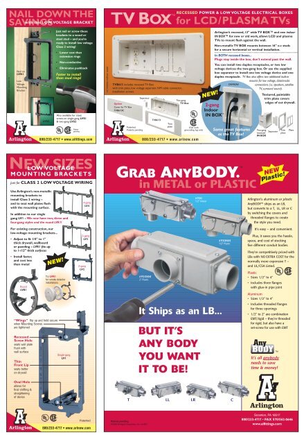
NAIL DOWN THESAVINGSwith this LOW VOLTAGE BRACKET© 2003, Rev 2007 Arlington Industries, Inc.Nail onLVN1LowVoltageMountingBracketArlingtonLVS2Just nail or screw thesebrackets to a wood orsteel stud – and you’reready to install low voltageClass 2 wiring!• Lower cost thanextension rings• Non-conductive• Eliminates pushbackFaster to installthan mud rings!Also available for steel;screw-on single-gang LVS1& two-gang LVS2Patentpending800/233-4717 • www.aifittings.com©2007 Arlington Industries, Inc.TV BOXfor LCD/PLASMA TVsTVB613 includes recessed TV Boxwith trim plate, low voltage separator, NM cable connector,installation screwsOptionCover for TV BoxTVB613CArlingtonPatented.Patents pendingSeparatorTVB613Trimplate800/233-4717 • www.arlnew.comRECESSED POWER & LOW VOLTAGE ELECTRICAL BOXESTwo-gangTV BoxCSA withgrounding lug onlyNEW!Arlington’s recessed, 13" wide TV BOX and new indoorIN BOX for new or old work, allows LCD and plasmaTVs to mount flush against the wall.Non-metallic TV BOX mounts between 16" o.c studsfor a secure horizontal or vertical installation.In BOTH recessed boxes...Plugs stay inside the box, don’t extend past the wall.You can install two duplex receptacles, or two lowvoltage devices the two-gang box. Or use the suppliedbox separator to install one low voltage device and oneduplex receptacle. TV Box also offers two additional built-inmounts for low voltage, data/mediaDVFR2Wconnections (i.e. speakers, satelliteTV, surround sound).2-gangIndoorIN BOX Same great featuresas the TV Box!Two-gangrecessedIN BOXTextured, paintabletrim plate coversedges of cut drywall.SeparatorTrimplatePlateNEW SIZESLOW VOLTAGEMOUNTING BRACKETSJust for CLASS 2 LOW VOLTAGE WIRINGUse Arlington’s non-metallicmounting brackets toinstall Class 2 wiring –and to seat wall plates flushwith the mounting surface.In addition to our singlegang LV1 – We now have two, three andfour-gang styles and the round LVR1!4-gangLV4GRAB ANYBODY.TMin METAL or PLASTIC#9301/2" MetalNEWPlastic!Arlington’s aluminum or plasticAnyBODY ships as an LB,but converts to a T, LL, LR or Cby switching the covers andthreaded flanges to createthe style you need.For existing construction, ourlow-voltage mounting brackets...• Adjust to fit 1/4" to 1"thick drywall, wallboardor paneling – LVR1 fits upto 1-1/2" thick surfaces• Install faster,and cost lessthan metalRoundLVR1NEW!Try LVR1for smoke detectorinstallations3-gangLV32-gangLV2#935NM2" Plastic#930NM1/2" PlasticIt’s easy – and convenient.Plus, it saves you the hassle,space, and cost of stockingfive different conduit bodies.They’re competitively priced withLBs with NO EXTRA COST for thenormally more expensive T –and UL/CSA Listed.Plastic• Sizes 1/2" to 4"• Includes three flangeswith glue-in pipe jointAluminum• Sizes 1/2" to 4"“Wings” flip up and hold securewhen Mounting Screwsare tightenedRecessedScrew Holeseats wall plateflush withwall surfaceThinFront Lipseats betteron drywallSingle-gangLV1It Ships as an LB...BUT IT’SANY BODYYOU WANTIT TO BE!• Includes threaded flangesfor three openings• 1/2" to 2" are combinationEMT/rigid – they’re threadedfor rigid, but also have aset-screw for use with EMTTMIt’s all anybodyneeds to savetime & money!Oval Holeallows forfinal shifting &straighteningof deviceTLLLRCArlingtonArlingtonPatented800/233-4717 • www.arlnew.comPatents pending©2006 Arlington Industries, Inc. rev507Scranton, PA 18517800/233-4717 • FAX 570/562-0646www.aifittings.com