Wadkin JV JVA JW JWA Double Disc Sander Manual and Parts List
Wadkin JV JVA JW JWA Double Disc Sander Manual and Parts List
Wadkin JV JVA JW JWA Double Disc Sander Manual and Parts List

Create successful ePaper yourself
Turn your PDF publications into a flip-book with our unique Google optimized e-Paper software.
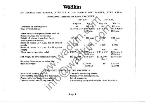
<strong>Wadkin</strong>30" DOUBLE DISC SANDER, TYPE J. V. A. 36" DOUBLE DISC SANDER, TYPE J. W. A.PRINCIPAL DIMENSIONS AND CAPACITIES :-30" J. V. 36" J. W.English Metric EnglishDiameter of s<strong>and</strong>ing disc 30" 760 mm 36"Size of work tables 2' 10" x l' 5" 860 mm x 3'4" x 1'7'"430 mmTable cants 45 degrees below <strong>and</strong> 10degrees above the horizontal.Height of tables from floor level 2' 10~" 880 mm 2'10~"Horse power of motor 5 5 5Speed of motor in r. p. m. for 50 cyclessupply 1,000 1,000 1,000Speed of motor in r. p. m. for 60 cyclessupply 900 900 900Floor space (machine only) 2'10" x 5'4" 860 mm x 3'4" x 5' 8"1625 mmNet weight in cwts (machine only) 18t (2,100 952 kilos 20 (2,240lbs. ) lbs. )Shipping dimensions in cubic feet(machine only) 83 2.35 cu. 89metresMetric915 mm1015 mm x583 mm880 mm51,0009001015 mm x1725 mm1016 kilos2.52 cu.metresDETAILS INCLUDED WITH THE MACHINE :-Motor <strong>and</strong> control gear.Two dust collecting hoods.Two s<strong>and</strong>ing diScs fitted to machine.Guards over s<strong>and</strong>ing discs.Press with two spare steel discs.Set of spanners.Two universal swivelling fences.Lubricating pump <strong>and</strong> sample tin of lubricant.www.wadkin.cominfo@wadkin.comPage 1
<strong>Wadkin</strong> OPERATING AND MAINTENANCE INSTRUCTIONSINSTALLATIONThe machine is despatched from the Works with all bright surfaces greased to prevent rusting.This should be removed by applying a cloth damped in paraffin or turpentine.FOUNDA TIONS.Foundation bolts are not supplied by <strong>Wadkin</strong> Ltd. unless specially ordered. Rag bolts t"(16 mm) diameter should be used to fix the machine to the floor. If the mill floor consists of4" (100 mm) to 6" (150 mm) solid concrete no special foundation is necessary. Cut 4" (100 mm)to 6" (150 mm) square holes in the concrete. When the machine has been carefully levelled itshould be grouted in position with liquid cement.WIRING.For complete cabling instructions see wiring diagram D. 191/3A <strong>and</strong> D. 586 on pages 9 <strong>and</strong> 10.DUST EXTRACTION.www.wadkin.comThe machine has two built in exhaust hoods, one for each disc, with 5t" (140 mm) diameteroutlets for piping connections.info@wadkin.comPage 2
LUBRICATION (See Fig. I}Every week thoroughly clean down the machine <strong>and</strong> using <strong>Wadkin</strong> Machine Oil Grade L. 4. renewthe thin film of oil on all bright parts not in constant use to prevent rusting.A 10 POINTS Give 1 or 2 depressions of the grease gun every month using <strong>Wadkin</strong> Ball BearingGrease Grade L. 6.WADKIN RANGE OF OIL AND GREASE LUBRICANTS WITH EQUIVALENTS :-<strong>Wadkin</strong> GradeEQUIVALENT LUBRICANTSShell Mex <strong>and</strong> B. P. Ltd. Vacuum Oil Co. Ltd. Caltex LubricantsMachine oil Shell Vitrea Oil 33 "Vactra" Oil Caltex AlephGrade L.4. (Heavy Medium) Oil.Ball Bearing Shell Nerita Grease 3 Gargoyle Grease Regal StarfakGrease Grade L.6. B. R. B. 3. No.2 Grease.BEARING LISTSizeNumberMakers' Number Per Where used onBore OlD Width Machine MachineHoff. R. 545 45 mm 120 mm 29 mm 1 <strong>Disc</strong> spindlewww.wadkin.comSKF. 1409 45 mm 120 mm 35 mm 1 <strong>Disc</strong> spindleHoff. W. 1i"Single Thrust1i" 2.7/32" 23/32" 2 Spiral Gear ShaftBearing.info@wadkin.comPage 3
<strong>Wadkin</strong>OPERATINGANDMAINTENANCEINSTRUCTIONSRecess to allowh<strong>and</strong>les 'Q' to beinserted intoof disc.Start <strong>and</strong> stoppush button controls.Four lubricationpOints lA' ongearbox.'E''FLUBRICATIONFRONT VIEW OF 36" DOUBLE DISC SANDER, TYPE J. W.(ALL PARTS INDICATED ARE COMMON TO 30" DOUBLEDISC SANDER, TYPE J. V. EXCEPT WHERE STATED).Two lubrication points tAlon motor.www.wadkin.comFIG. 1.~------------'D'info@wadkin.com'N'·Universal table fence.(36" <strong>S<strong>and</strong>er</strong>, only)'J' (Scale <strong>and</strong>pointer)only)
<strong>Wadkin</strong> OPERATING AND MAINTENANCE INSTRUCTIONSCHANGING OF DISC (See Fig. 1). Move the table horizontally away from the disc by rotating h<strong>and</strong>wheel 'M'. The small knurled h<strong>and</strong>wheel'N' holding the guard in position over the face of the disc should be unscrewed. This leaves the guardfree to be swung out of the way on the pivot 'P' securing it to the guard covering the back of the disc.Detach the two h<strong>and</strong>les 'Q' from the body of the machine <strong>and</strong> screw into the holes tapped in the rim of thedisc. The guard over the rim of the disc is cut out in two opposite positions to allow the h<strong>and</strong>les to beinserted into the rim of the disc whilst it is still fitted to the machine. Take out the four screws 'R' byunscrewing them from the back of the disc. Using the two h<strong>and</strong>les lift the disc off the driving flangeplate <strong>and</strong> clear of the machine.Follow the reverse procedure when replacing the disc after a new abrasive has been attached.NOTE: Care must be taken to remove the h<strong>and</strong>les from the rim of the disc before putting the machine touse.CHANGING OF ABRASIVE.To remove a worn abrasive from the s<strong>and</strong>ing disc immerseit in a bath of hot water <strong>and</strong> leave for ten to fifteen minutes;when the paper will peel off. While the disc is in the bath,scrape <strong>and</strong> clean off all the old solution. Remove it fromthe bath <strong>and</strong> leave it to dry.When attaching a new abrasive the disc should be laid flaton a bench. Coat the surface with a thin layer of <strong>Wadkin</strong>Adhesive Cement Grade C. 5. If it is extremely cold thecement should be warmed before use. Spread to an eventhickness with a roller or squeegee <strong>and</strong> leave until tacky.Afterwards put on the sheet of abrasive paper. The disccementing press as illustrated in Fig. 2 which is suppliedcompl ete with two s<strong>and</strong>ing discs is now used. Place thenewly prepared disc in the press <strong>and</strong> by the aid of one ofthe other spare discs clamp <strong>and</strong> ieave for 12 hours or untilrequired whichever is the longer.www.wadkin.cominfo@wadkin.comcPress.
DUST COLLECTION.As already mentioned hoods are providedbelow the tables for collecting the dustwith outlets arranged to connept to anexhaust system. If a main dust extractingsystem is available the machine hoods maybe connected direct to the main suctionpiping.Alternatively a compact self-containeddust collector can be supplied as illustratedin Fig. 3. This unit very efficientlyh<strong>and</strong>les the fine dust <strong>and</strong> is recommendedwhere one machine only is installed. Itembodies a dust storage bin of four cubicfeet capacity made quickly detachable foremptying purposes. The dust laden air isfiltered through a series of flame-proofedfabric sleeves, while a motorised. shakingmechanism for periodic shaking preventsaccummulation of excessive dust. Fulldetails for operating <strong>and</strong> maintenance of theunit are given on an Instruction Sheet insidethe top lid of the unit.FIG. 3If the work consists of radio <strong>and</strong> televisioncabinets it is advisable to inform us in orderthat the correct type of dust collector is offered.Where a number of s<strong>and</strong>ing machines are installed a separate system of dust collection quite distinct fromthe main suction plant is recommended. Advice on this will be given on request.www.wadkin.comABRASIVES.Garnet Paper <strong>Disc</strong>s of varyirig grits <strong>and</strong> grades can be supplied to suit the class of work <strong>and</strong> the desiredfinish on woodwork. <strong>Disc</strong>s of either 30" or 36" diameter with a 2t" diameter centre hole are available.Where it is desired to use the machine for metal working, suitable discs can be supplied in the followinggrades:- Aluminous oxide, St<strong>and</strong>ard emery cloth, Silicon carbide <strong>and</strong> Corundum.info@wadkin.comPage 7
<strong>Wadkin</strong> OPERATING AND MAINTENANCE INSTRUCTIONSELECTRICAL INSTALLATION INSTRUCTIONS.The cabling between the motor <strong>and</strong> the control gear has been carried out by <strong>Wadkin</strong> Ltd., <strong>and</strong>it is only necessary to bring the line leads to the machine for it to be put into service. Thisshould be done as follows :1. Fit triple pole isolating switch near the machine unless it has beensupplied to special order by <strong>Wadkin</strong> Ltd. when it will be fitted <strong>and</strong>connected to the machine.2. Connect the line lead to the appropriate terminals. See, diagram ofconnections. The cables should be taken to the machine in conduit <strong>and</strong>secured to the control gear by locknuts.3. Connect solidly to earth.4. Close isolating switch <strong>and</strong> press start button. If motor does not rotatein the right direction, interchange any two incoming line leads.FAILURE TO START.1. Electric supply is not available at the machine.2. Fuses have blown or have not been fitted.3. Isolating switch has not been closed.4. Lock-off or stop button has not been released.STOPPAGE DURING OPERATION AND FAILURE TO RESTART.'1.Fuses have blown.2. Overloads have tripped. They will reset automatically after a shorttime <strong>and</strong> the motor can be restart ed in the usual manner.ADJUSTMENTS.For a finer overload setting, set the load indicator to a lower value <strong>and</strong> vice-versa for a lessfine setting.GENERAL.Check the earth connect~on from time to time. Users are r,ecommended to display in anappropriate position in the maintenance department a <strong>Wadkin</strong> Electrical Maintenance InstructionCard, No. 356, which is issued gratis on application.www.wadkin.cominfo@wadkin.com
--=0()",.• Z..III.J...«III.JIIIIIIU)It:«. III\9.J«u. 0:..U.III.JIII III0Z ·olIIII 0It:III....LbJ \!lIt:III ZIt: .
MAIN PI5CONNE:CT!>WITCH./I- -- --------------- - ---- - -,~-,III,I,rl-PA----,.---f----,MAGNET COIl....AINT"IN CONTACT.OVE:RI.OAD He:PlTE:RC011.5.iL--F'------,F---=:-.:j~-=~==1~-:-, ttt-~~::~±L::-:~~,---i'---OVERI.OAD . TRIP !>WITCH.r Go l' I, j _____________ J:~----- - - -- ------ -- - --~...-TYPE FtA. SIZE N"\ MAGNETIC ST"RTER.r Tl Ta [r --,MOUNTED ON ClOOR. OF CONTROL GEAR CAVITY.,(7,A BeT""[i , : ~" , I r.--'It [ I I11 1 I I __ ..JJ r : ~~ t I ,,J ________ --550VOL.T MOTOR.I-6T,,'RT "'1!.~r,IIII 5TOP I, t...: ________ J ,,,....--f::-PU&H BUTTON &TATION.DUAL. Y 0 L. T AGe: MOTOR CONNE'.C TION5.WHEN OUAL VOLTAGoE: WHEN DUAL. VOL TA"'EMOTORI> ARE: I>UPPLIE:D MOTOR'!> A!=IE 5UPPLIEDWITH e I..EAD!. THE. WITH b I..EADS THECONNECTION5 SHOWN CONNECTION!> 5HOWNBELOW ARE: NECE5&ARY. BELOW ARE NECi:5SARY.~ERIE:!,/STAR - 4401,101.. T!!>. STAR - 340/440 VOI..T& .PARALI..E:L/STAR - 2201,101.. T£>. DEI.. TA - 200/250 V01.. TS.TOTI-Ti!-T:!!AT STAJ;l.TE:R.TO TI-Ti!-T3 TO TI-Ti!-T3 TO Ti-T2-T3AT &TAflTER_ AT5TARTER. AT STARTER.A4 B4 C4 ~. C4A3 83 C3 A3. &3 C;3Ai! Be Ci! AI! SI! C2ttJBeAlCi!BIAa Ba /c2.'.~ :.. CI r.~CISERIE:5/STAR PAP.~L.LEl.,/sTA'9 L.E:AD MOTOR!:>. 6 LEAD MOTORE),www.wadkin.comINSTAL.LATION INSTRUCTION!;>.FIT MAIN DISCONNECT £>WITCH NE:AR M""CHINE SO THAT THE. ELECTRICAL. GoEAR MAV RE:ACII..Y BE:'· ISOLATED I"ORINSPECTION PURP05ES •. BRING !!IUPPI..Y CABLES TO DI5CONNE:CT I>WITCH ANO TO I.I-L2.·1.3 AT M""GNE:TIC ST""RTE:R. THROUGH CONOUIT WHICH £>HOUI..O BE: SCRe:WE:O INTO THE MACHINE: FRAME'. AND SECUREO BY ME:AN5 of 1..0C.KNr:JT&.ENSURE THAT THE OIRECTION OF ROTATION 01" THE MOTOR. 15 CORRECT BEFORE PUTTING THE MACHIN" INTOSERVICE. TO REVER5E: ROT .... TION INTERCHANGE: L.I AND 1..:3 AT. MACONETIC !!ITARTER.OPERATING IN5TRUCTION&. .' • • •TO 5T .... RT M .... CHINe:: CI..OSE MAIN Ol5CONNECT 5WITCH ANO PRE&5 5TART BUTTON. TO STOP MACf.lINE: PRe:&& STOPinfo@wadkin.comBUTTON_ TO 1..0CK 01"1" MAC.HINE: PRt~S AND TURN 'STOP' BUTTON,THI& MUST Bi: R£I..E",,",,£O BEF'OR(;:. A .. TART CANBe: MAOE.OVE:RI.OAD.5HOULO THE MACHrNE: STOP OUE TOOVE:RLOAD. THE. OV"RLOAD TRIP IWITCH 5HOU1.C BE RE5E:T BY OEPRE5&IN .... TH~ PLUNaoE:R ON THE OV£RL.OAD A5&£MBLY. THEN START IN THE USUJO-!.. MANNER.
· . . blow away harmful dust,chips <strong>and</strong> dirt with a<strong>Wadkin</strong> Electric BlowerNo motor can run at its maximum efficiency with its ventilatingduct or control gear covered with dust <strong>and</strong> dirt. Sooner or laterthe resultant overheating will cause serious trouble.Similarly. accumulations of chips <strong>and</strong> dust. in the mechanical parts ofthe ma'chine can interfere with its efficiency. A few minutes a weekfor blowing down all Woodworking Machinery will be amply repaidin better <strong>and</strong> easier running. in increased life. <strong>and</strong> freedom frombreakdown.Blowers can be supplied for single phase A.c. or Direct Currentfor any voltage Lip to 250.Please state voltage when ordering.www.wadkin.cominfo@wadkin.com