Wadkin C5 C6 C7 C8 C9 Bandsaw Manual and Parts List
Wadkin C5 C6 C7 C8 C9 Bandsaw Manual and Parts List
Wadkin C5 C6 C7 C8 C9 Bandsaw Manual and Parts List
- No tags were found...

Create successful ePaper yourself
Turn your PDF publications into a flip-book with our unique Google optimized e-Paper software.
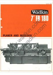
POWER BAND RIPSAWMODEL "C" RANGEwww.wadkin.comOPERATING & INSTRUCTIONS MANUALinfo@wadkin.com
l! Ji , ;, -! J!i OPERA TING AND INSTRUCTION! :, ,I ,, '-I MANUAL, )J ' I 'I '~ !, J, II].! I, :,i 'I', IFOR&pbWER BAND RIPSAW. ~~.www.wadkin.cominfo@wadkin.com: i"\' .', II: __ ~--n: I, IJ
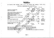
Modifications are made to these books from ti(1le to time <strong>and</strong> it is importanttherefore that only the book sent with the machine should be used, as 8working manualBOOK No.'B.684PLEASE INSERT SERIAL NUMBEROF MACHINESpecificatiDn<strong>C5</strong>Diameter of Wheels 5QOmm 19.7inWidth of Saw Blade (max) 25mm 1inLength of Saw Blade· (max) 4166mm 164in-.Length of Saw Blade (min) 4p13mm 158inDepth under Saw Guide 410mm 16.14inMaximum cut width 480mm 18.9inSpeed of motor. 50Hz t3000rev/minSpeed of motor. ~OHz 3600rev/minPower of-motor 1.5kW 2hp"2,25kW 3hpSize of table500x700mm,19,7X27,5inHeight of table850mm 33.5inFloor space55!JX8SDmm21,7x35inWeight (approximately) 220k9 4851bSpeed of Saw Blade 1500m/min5000ft/minTable Tilts (~t<strong>and</strong>ard) 0-45 0OPTIONAL EXTRAS.range<strong>and</strong>Power B<strong>and</strong> Ripsaw.~0-45 0 0-35 0 0.35 0 0-35 0<strong>C7</strong> CB<strong>C9</strong>Omm 23.61n 700mm 27.51n BOOmm 31.5in 900mm 35.5in30mm 1.18in 40mm 1.6in 40mm 1.6in 45nim 1.Bin4496mm 177[n 50BOmm 200in 5538mm 218in 63l0mm 248in4343mm 171'in 4902mm 193in 5360mm211in 61 i Omm 2401n,470mm 18.5in 485rnm 19in 530mm 20.75in 600h'lrTL 23.5in580mm 22.8in 6BOrnm 26.7in 7BOmm 30.7in 780mhl __ ~. 75in3000rev/min 3000rev/min 3000rev/min 300Drev/min3800rev/min 3600rev/min3600revtmin .3600revhilin2,25kW 3hp 3kW 4hp 4kW 5,5hp 5,5kW 7,Shp'3kW 4hp *4k.W 5,5hp *5.5kW 7,5hp600x83Omm 765x1000mm 765x1100mm 765"x 1200mm23.6x32.7in 30x39in30x43ln30x47in850mm 33.5in SOOmm 35in 955inm 37ih 1000mm 39in600x.1020mm 770x1340mm 770x1340mm 770x1440mm23.6x40.6in 30x52.7in30x52.7in 30x56.7in260kg 5731b 483kg 10641b 508kg 1120lb 533kg 1176lb1500m/min1500m/min1500m/min 1500m/min5000ft/min5000ft/min5000ft/min 5000ft/minwww.wadkin.cominfo@wadkin.comTELESCOPIC TOP SA\lGUARDSAW TENSION INDICATORRIP FENCE FOR REPLACEMElNT PARTS, TOOLS AND ACCESSORIES,MI'l!RE FENCE CONTACT;- WADKIN CLEVELAND (Divieon of <strong>Wadkin</strong> Limited)FOOT BRAKE NORTH LIVERTON nmUSTRIAL ESTATEH.P. MOTORLOFTUS-c---ELECTRICAL-INTERLOOKING-FOOTBRAKE--c-SALTBumT-BY-THE-SEA----------c------BOTTOM GUIDECLEVELANDENGLAND(Telephone: Guieborough 0287/40177).
2:INDEXSafety of Woodworking Machines.Safety.Full view <strong>and</strong> Description of Machine.Slinging Instructions.Installation.Foundation.Wiring Details.Lubrication.Dust Extraction.Fitting H<strong>and</strong>saw Blades.Tracking of Sawblade.on Wheels.Tensioning Sawblade (Without tension scale).Tensioning Sawblade Us~ng Scale (Extra).Adjustment of Sawblade Tension Scale (Extra).Setting Top Sawguide Unit.Setting Bottom Sawguide Un4t (Extra).Table Canting Instructions.)Table 90 0 Positive Stop Adjustment.Table Square to Sawblade Adjustment.Rip Fence (Extra).Mitre Fence (Extra).",;Starting -Stopping MachinEi'.Footbrake' (Extra).Saw Wheels.Removal of Top Saw Wheel.Removal of Bottom Saw Wheel.www.wadkin.cominfo@wadkin.comPage 4Page 5Page 6Page 7Page 8Page 8Page 8Page 10Page 10Page 10Page 12Page 12Page 13Page 13Page 14Page 14Page 17Page 17Page 17Page 19Page 19Page 19Page 19Page 20Page 22Page 22
3INDEX (Cont'd)Belt Tension Adjustment.Table Insert.Sawdust deflector.Maintenance of B<strong>and</strong>Baw BladBs.Maintenanoe of b<strong>and</strong>Baw Blades.General Causes of Saw Trouble.Folding B<strong>and</strong>Baw Blades.Hints on Cutting.B<strong>and</strong>Baw Blade ·<strong>List</strong>.MACHINE PARTS INDEXBase, Top Cover <strong>and</strong> Doors .Assembly.Wheels <strong>and</strong> Belt Assembly.Table Assembly.Motor Mounting Assembly~Top Sawguard Assembly..Under Table Guard Assembly.Table Mounting Bracket on Base.Bottom Spindle Asssmbly.Top Spindle Assembly.Top Slide Assembly.Top Guide Assembly.Bottom Guide' Assembly. (Extra).Tracking Assembly.www.wadkin.comBrake Assembly (Extra).Saw Tension Indicator Assembly (Extra) .Delux Top Sawguard (Extra).Rip Fence Assembly (Extra).Extension Table Assembly (<strong>C9</strong>)Wheels <strong>and</strong> Belt Assembly (<strong>C9</strong>).PO\'ler B<strong>and</strong> Rip SaHPage 23Page 25Page 25Page 25Page 26Page 29Page 29Page 31Page 31Page 32Page 34Page 36Page 38Page 40Page 42Page 44Page. 46Page 48Page 50Page 52Page 54Page 56Page 58Page 60Page 62Page 64Page 66info@wadkin.comPage 68.Page 71.
4HEALTH & SAFETYSAFETY OF WOODWORKING MACHINESWoodworking machines can be dangerous if improperly used.range of work of which they are capable, requires adequateding arrangements against possible hazards.The widesafeguar-Many injuries to machinists are caused by carelessness or failureto use the guards provided or to adjust them· correctly.WADKIN LTD., supply machinery designed for maximum safety which theybelieve, as a result of thorough testing, minimizes the risks inevitablein their use. It is the user's responsibility to see that thefollowing rules are complied with to ensure safety at work:1. The operation of the machine should conform to therequirements of the Woodworking Machines Regula':'.tions 1974. All guards should be used <strong>and</strong> adjustedcorrectly.2. Safe methods of working only should be adopted asgiven in the Health <strong>and</strong> Safety Work Booklet No.4l,"Safety in the Use of Woodworking Machines",(obtainable from Her Majesty's Stationery Office)<strong>and</strong> as advised by <strong>Wadkin</strong> Ltd.www.wadkin.com3. Only personnel trained in the safe use of a machineshould operate it.4. Before making adjustments or clearing chil"s, etc.,the machine should be stopped <strong>and</strong> all movementshould have ceased.info@wadkin.com5. All tools <strong>and</strong> cutters must be securely fixed <strong>and</strong> thespeed selected must be appropriate for the tooling.SAFETY IS OUR WATCHWORD BUT THE· USER MUST COMPLY WITH THEABOVE RULES IN HIS OWN INTEREST. WE WOULD BE PLEASED TOADVISE ON THE SAFE USE OF OUR PRODUCTS.
5SAFETY1. Read Instruction Book.2. Securely Lock Cutters.3. Set Guards Correctly.4. Select Correct Speed.5. Use Feeding Devices Where Possible.6. Electrically Isolate Machine During Maintenance& Setting Up Operations.7. Refer To HSW Booklet No.41. (in UK) ForSafety In The Use Of WoodworkingMachinery.www.wadkin.cominfo@wadkin.com
6 500mm & 600mm <strong>B<strong>and</strong>saw</strong>sTypes <strong>C5</strong> &<strong>C6</strong>START-~'rf""\DBOTTOM DOOR--1DOOR LATCHTOP SAWGUlDE RISE& FALL LOCKINGHANDWHEELwww.wadkin.cominfo@wadkin.comEXHAUSTCHUTE'nC)OR LATCH
7:BANDSAW SLINGING INSTRUCTUIOllS.To litt b<strong>and</strong>aaw proceed as 1"olloWBI-1. Open top door 01" machille.2. Position minimum length sling 01" 5 metres (16 1"ee.t) arouod top 1"rame <strong>and</strong>behind top whsel as showo in l'HOTO 1 <strong>and</strong> PHOTO 2.NOTE:- To prevent damage to sling <strong>and</strong> 1"rame, plaae raees between Blioga.<strong>and</strong> machine as shown.3. Secure door to top sawgudda rise <strong>and</strong> 1"all looking h<strong>and</strong>wheel by strongcord as shown in PHOTO 3.4. Prooeed to slcwlylitt b<strong>and</strong>aaw ensuring that b<strong>and</strong>aaw is not titling at anangle.IMPORTANT:A MINIMUM LENGTH SLING OJ' 5 MEll'lIES (16 FEET) WITBIli THE SAl'EWOllKING LOAD MUST ALWAYS BE USED.PHOTO 1 PHOTO 2www.wadkin.cominfo@wadkin.comPHOTO 3
8INSTALLATION.Remove proteotive ooating from all bright parts by applying a cloth soaked inp8.1'a'f'fin, turpentine or o:t:hersolvent.When themaohine is cased for export,the top cover, top door, top Wheel <strong>and</strong>table are rsmoved <strong>and</strong> packed individually.Re-assemble machine as follows:1. Secure top cover "A"FIG,1, to top of main frame by bolts "B".2: Fit top wheel to spindle <strong>and</strong> secure .by 1 - bolt <strong>and</strong> flange washer, see FIG,2.3. Locate top door on hinges, FIG.3, <strong>and</strong> bottom door on hinges, FIG,4.4. Position table on mainframe quadrant <strong>and</strong> secure by 4 - bolts <strong>and</strong> washers "A",FIG,5. (Table removed for export orily).l'OllNllATION •See enclosed £oundationdrawing for bolt posi t:Lons <strong>and</strong> clearance required.When installing machine, level by packing under base. Foundaticn bolts are notsup'pliedwiththe maohineeltcept by special order.WIRINGDEIl'AIIS •The motor <strong>and</strong> control gear have been wirsd in before despatch.zequiredistooonnBct the 'powsr supply to the starter.Points
9FIG 1 FIG 2FIG 3 FIG 4www.wadkin.cominfo@wadkin.comFIG 5.. __ ._----
.10LUBRICATION •It is advisable to keep aU bright parts covered with a thin film of oil topmvent roating. Cleansawduet.from inside main frame weekly.See enclosed Foundation Drawing for lubrication points.Type fo Grease Recommended: CASTROLSl!HEEB.OL AP.). or equivalent.DUST EXTRACTION.The machinahaea built in duet chute with a 100mm dia. exhauet outlet <strong>and</strong> canbe connected to main duet -extract"on plant if desired.FITTING l!ANDS:AW ;BLADES.1. Isolatemachina .electrically.2. Open top <strong>and</strong> bottom doore of main frame.3 •. Loosen cap head bolts "A", FIG.6. <strong>and</strong> rsmove sawguard "B".4. LooeelOl thumbscrew "A", FIG. 7, <strong>and</strong> move guide "B" :to eJ
11FIG 6 FIG 7FIG 8 FIG 9www.wadkin.cominfo@wadkin.comFIG 10
TRACKING OF SAWBLADE ON 1o/!OOi)LS.Every aawblade has dif'f'erent running characteriai tcs on a b<strong>and</strong>saw machine~ due toTRACKINGOFSAWBLADE ON wm:ELS.Everysawblade .hasslightlydif'f'erent running characterisi tics on a b<strong>and</strong>saw machinedue to the condition of' the steel ribbon f'rom which the blade is made, the bladejoints <strong>and</strong> tension in the blade ribbon. This is compensated by using a crownedorsUghtly curved tyre on the wheel<strong>and</strong> providing the top wheel with slight tiltingadjuStment.To check the tracking of'sawblade, f'ollow the undementioned procedure:1. Isolate machine electrioally.2. Open top ~<strong>and</strong> bottom doors.). Rotate the top wheel slowly by h<strong>and</strong> in a clockwise direction <strong>and</strong> check theblade is running oentral on the wheels.4. If' not rllnning central, loosenwingnut "B",FIG.B, then turn h<strong>and</strong>wheel "C"untillsaw .i:s tracking correctly, i.e. in the centre of' both wheels.5. 'When tracking is. correct, tighten wingnut "B". This adjustment is mostimPortant, ·that thesawbJ.ade, when tracking co=ectly,passes in a straightlinebstween top <strong>and</strong> bottom wheels <strong>and</strong> does not shake, - when the latteroccurs, the back of' thesawblade keeps hitting the back guide roller <strong>and</strong>------DANGER: DO NOT TRACK BLADE WITH MOTOR RUNNING.TENSIONING SAWBLADE. (Without tension scale).Thesawblade shouJ.dal~ be tensioned correctly to achieve ma.ximum blade life.~e:t'-tension 04:tJiLadecoul:d result in saw damage.To tension bJ.ade co~ctly, proceed as follows:1 .• Isolate ma.chinselectrically.2. Turnh<strong>and</strong>wheel "All FIG.B, until blade can be pulled 61IDD (t") from itstrue line at central point between wheels. Blade is then tensioned co~ctly.www.wadkin.cominfo@wadkin.com
13TENSIONING SAWBLADE USING SCALE (EXTRA).The sawblade should always be tensioned correctly to achieve maximum blade life.Over-teniion or under-tension could result in saw damage.To tension blade correctly, proceed .as followsl1. Isolate machine electrically.2. Open top door of machine.3. Tum h<strong>and</strong>wheel "A", FIG; 10, until pointer on scale "B" points to theoorresponding width of blade being used.Blade is then tensioned oorrectly.ADJUSTMENT OF SAWBLADE TENSION SCALE (EXTRA).The scale <strong>and</strong> pointer are accurately set before despatch from the works. Shouldthis be displaced for any reason, cheok the soale by the undennentioned prooedure:1. Isolate machine electrically.2. Tension the sawblade as previously disoribed until it can be pulled:i" (6mm)from its true line at a central point between the two wheels.3. Check that scale indioates oorrect sawblade width. If scale is incorrect,tension sawblade to maximum tension by h<strong>and</strong>wheel "A", FIG.11.NOTE: For safety! the blade used during this adjus.tment must be wider than1" (25;4mmJ.4. When maximum blade tension is attained, loosen M8 socket head grubscrew "B"Then move coller "c" until pointer on scale indicates maximum blade width of1~" or 4Omm.When set, relock M8 grubs crew "B".5. Tum tension h<strong>and</strong>wheel "A" until soale corresponds to width of blade fitted.NOTE: When scale has been set using above procedure it will read correc.tlyr;;;: any width of blade within the range of the machine without further alteration,even if length of .sawblade varies for any given. width •. For a 20mm wide blade, the· pointer should read 20, etc.rr the machine is left st<strong>and</strong>ing for a period, e.g. overnight, the tension shouldbe reduced, <strong>and</strong> the blade re-tensioned before putting the maChine into operationagain.www.wadkin.cominfo@wadkin.com
14SETTINGTOPSA1IKlUIDEUNIT.A sawguide unit "A", FIG. 12 , is fitted above the table <strong>and</strong> is fully adjustablefor adequate aawbladesupport. The unit is fitted with TELLO!!" cappeL b 'b:leclcsaftda long rirebe6ziag.~I A similar guide unit for below the table can be supplied as an optionalextra.To set top guide assembly, proceed as follows:1. Isolate machine electrically.2. Loosen caphead screws "B", FIG11, arid remove sawguard "C".3· ,Loosen grubscrew "A" <strong>and</strong> M10 nut "B", FIG.12. then position guide body "C"central <strong>and</strong> parallel to blade'SEE FIG. 13, then tighten up grubs crew "A" <strong>and</strong>M10nut "B", FIG.12.NOTE: Once the guide ,has been initially set up, adjustment as described in- paragraph 4 should only be necessary.4. Slacken thumb screw "Y" FIG.12, <strong>and</strong> set rear guide roller 1/64" clear ofback of blade ,lockup thumbscrew "Y".S. 'Slacken thumb screws "X" FIG.12, <strong>and</strong> move side guide foreward as positionedin FIG.14, then pivot side guide rollers on anti lock eccentrics just clear.of blade FIG. 13, <strong>and</strong> lock thumb screws"X"NOTE: It is important that side guide rolle,i-a do not nip blade are set justclear.6. Refit sawguard "C", FIG.11 <strong>and</strong> secure with caphead "B".TO VERTICALLY ADJUST TOP GUIDE UNIT, PROCEED AS FOLLOWS:1. Isolate machine electically.2. Hold guide assembly "A", FIG. is, then 100Jen h<strong>and</strong>wheel "B".J). l'ositiongu1de assembly "A" as required then relock h<strong>and</strong>wheel "B".SETTING BOTTOM SAWGUIDEUNIT IF FITTED AS OPTIONAL EXTRA.The bottom sawguide unit is fitted below the machine table <strong>and</strong> is set ~ingsimilar procedure to top sawguide unit.www.wadkin.cominfo@wadkin.com
15FIG 13Correct1 "I+- i'64 tI Rear GUide*/Roller tSideGuideRoilerswww.wadkin.comI~7IncorrectFIG 14info@wadkin.com
16FIG 17 FIG 18FIG 19 FIG 20www.wadkin.cominfo@wadkin.com
17~.The table cants to ·the right.To cant table proceed as follows:1. Support table weight.2. Loosen }ever "A" Fig. 17. (<strong>C5</strong> & 6) Loosen Nut "A" FIG.20. (<strong>C7</strong>,8,& 9).3.'Cant table to ~quired angle.4. Relock "A".TABLE 90 0 POSITIVE STOP ADJUS~T.oThe table 90 positive stop is set correctly before despatch from the works butshould this setting be disturbed for any reason, follow the undermentionedprocedure:1. Isolate machine electrically.2. Ensure top guides ( <strong>and</strong> bottom guides if fittsd. ) are clear of ths blade, so itis not restricted in any way.3. Check blade is square to table by means of a steel square.4. If adjustment is necessary, loosen lever "A",FIG.17, <strong>and</strong> M12. Locknut "A".FIG.18.5. Set table square to sawblade by the s.teel square then rslock lever "A" ,FIG. 17 •6. Turn screw "B",FIG.18, until it locks against undersids of table then relockM12 Locknut "A".TABLE SQUARE TO SAWBLADE ADJUSTMENT.The table is set squars to sawblade, from front to rear, before despatch from works.Should this sstting be disturbed for any reason, check the following:1. Isolate machine electrically.2. Ensure top guide (<strong>and</strong> bottom guides if fitted) are clear of sawblade so blade isnot restricted in any way.3. Check blade is tracking correctly, i.e. ~!nning in the centre of each wheel, .(Ses Tracking of Sawblade instructions, page 12.)4. Check blade for square to table by means of a steel square.www.wadkin.comIf adjustment is necessa;Y. proceed as fol~oWB:1. Loosen M20 Looknut "A",FIG.19, <strong>and</strong> MfO bolt "B".info@wadkin.com2. Insert small toggle (not supplied) into holes in M20 adjusting screw "C" <strong>and</strong>turn screw "C" until table is set square to sawblade.3. lihen table is set square to sawblade, ti8hten M10 bolt "B" <strong>and</strong> M20 locknut "A".4. Resst top guide (<strong>and</strong> bottom guide .if fitted).
18MITRE FENCEwww.wadkin.comFIG 21 ..STOP RODinfo@wadkin.comSTOP'RODSi---I---------M-ITRE-FENeE------------------I---FIG 22
· ; ,19RIP FENCE (EXTllA).A rigid rip fence FIG.20, is mounted on a round slide bar fitted to edge. of table.This fence can be mounted to rip either to inside or outBide of b<strong>and</strong>eaw blade.MITRE FENCE (EXTRA, SUPPLIED WIT!{ MACHINE :BY SPECIAL ORBIm).The mitre fance "A" in FIG.21. slides in the table slot. Two stop rode ":8" areheld together by two clamps "H" <strong>and</strong> wingnuts "C". The stop rode are secured tofence body by thUmbscrew liD".mlnl: Always ensure the s.top rode are set clear of the sawblade or. serious damagewill result when maohine is operated.The mitre fence can be rotated through 90 0 with positive stops. at 90 0 <strong>and</strong> 45 0 •To positi-on mitre fence at required angle, loosen h<strong>and</strong>wheel "E" in FIG.21, thanpull plunger "F" from location, position fence as required using scale "G" thenrelook h<strong>and</strong>wheel "E".mlnll Always ensure table slot is clear when using mitre if'ence.MITRE FENCE STOP RODS. (EXTRA)Accurate repetitive cutting can be made using the stop rode, see FIG.22.The rode are held in the fence by the thumbscrew "D" in FIG.21, <strong>and</strong> the stop rodeheld together by the two clamps "H".To adjust the rode by the clamps, loosen the wingnuts tIC".STARTING - STOPING.Start <strong>and</strong> Stop buttons are situated on the column of machine as shown in FI(h23.FOOTBRAKE (EXTllA).A footbrake is situated in the base of the machine as shown in FIG.24.mlnl: Always press "STOP" button before depressing footbrake.www.wadkin.cominfo@wadkin.com
2DSAli WHEEJ..')Isolate ma.chine electrically, <strong>and</strong> clear top <strong>and</strong> bottom tyres daily to preventa.ccumulation of sawdust which could cause bla.deto run from trus line.J3a.dlyWOl:ll tyresshould be repla.csd, as worn tyres causs saw vibration resultingin uneven sawing <strong>and</strong> saw breakages.In order to a.chieve best results thsurethanestretch on tyres should be spot gluetat intervals of 8" to 10" a1iOund peripheral diameter.www.wadkin.cominfo@wadkin.com
21FIG 25www.wadkin.cominfo@wadkin.comFIG 24
REMOVAL OF TOP SAW WHEEL.:To remove top saw wheel proceed as follows:1. Isolate machine elec trically •2. Open top <strong>and</strong> bottom doors of main frame.3 •. 1temove b<strong>and</strong>eaw blade ·byreversiDg procedure for "Fitting B<strong>and</strong>eaw Blade", Page.10.4. Remove bolt <strong>and</strong> washer from centre of top wheel, FIG,25.5 •. <strong>Manual</strong>ly support weight of wheel<strong>and</strong> caref'ul.l.y pull wheel from spindle.liEMOVAL OF :BOTTOM SAW WHEEL.To remove bottom saw wheel,proceed as follows:1. Isolate machine electrically.2. Open top <strong>and</strong> bottom doors of main frame.3 • Remove b<strong>and</strong>eaw blade by reversing procedure for "Fitting B<strong>and</strong>eaw Blade", SeePa.ge.10.4. I.oosen 2 - M12 nuts "A", FIG.26, ·<strong>and</strong> M12 locknut "B".5. Turn M12 nut liB" anti-clockwise, releasiDg belt tension sufficient enough forbelt to be removed from pulley •.6. Remove bolt <strong>and</strong>wa.sher "A", FIG,27, from centre of bottom saw wheel.7. Manllally support weight of saw wheel <strong>and</strong> pull wheel. from spindle.www.wadkin.cominfo@wadkin.com
23BELT TENSION.Incorrect tension is the major oause of premature belt failure, some of itseffects are as followsl1. Under-tensioning results in incorrect driven speed caused by belt slip;this oan be corrected by inoreasing tension. "2. Over-tensioning can be more serious. Apart" from obvious damage to the belt,it can oause overheated, damage or burned out motor front end bearings.This is usually preoeeded by excessive stretch or too many take ups.The POLY-V drive belt is ccrrectly tensioned before the machine leaves the works.After a period of time, the be~t may start to slip due to run-in stretch <strong>and</strong> shouldbe retensioned oorrectly as in "Belt Tension Adjustment".BELT TENSION ADJUSTMENT.TO TENSION POLY-V-BELT. PROCEED AS FOLLOWS:1. Isolate machine electrioally.2. Open bottom door of machine.3. Loosen 2 - M12 nuts "A", FIG.26.4.5.Loosen M12 locknut "B".Turn M12 nut "B" to point where belt slackness is juilt eliminated from pulleys.(Note: To feel belt, place h<strong>and</strong> behind wheel).6. Turn M12 nut "B" clockwise 2 full turns when correct belt tension should beattained.7. Relock M12 locknut "B" abd 2 - M12 nuts "A".8. Plose bottom door of machine.www.wadkin.cominfo@wadkin.com
24~91 -,-1&532,35-105 ( )L 45"633L..-L:-J:".:T-......I -16"-'I. '" '"i-2S--J13 L-I ---.:......____...;....__If Sawdust Deflector ¥-"';;45 0 FIG 29www.wadkin.cominfo@wadkin.comf
SAWDUSTDEFLECTOR.When machine is operating, most of the sawdust will be passed out via the dustexhaust outlet but !nevi tably some dust will be carried down with the bladecausing a gradual sawdust accumulation in the machiDe base. This sawdustacoumulation can be slowed down considerable by fitting a sawdust deflectornear to the dust exhaust outlet as shown in FIG. 28. These 2 sawdust deflectorpads can be easily made from wood following the drawing FIG.29.B.When fitting to machine, move deflector. pads as close to. blade as possiblewithout touching blade t)len secure in position by 2 - hexagon head ~creWB <strong>and</strong>washers.MAINTENANCE OF BANDSAW BLADES.A properly sharpened b<strong>and</strong>saw blade will give clean, accurate. cutting <strong>and</strong> thisis achieved by proper setting <strong>and</strong> sharpening of the teeth. Al_ys set the teethbefore sharpening.SETTING.In order to cut satisfactorily, b<strong>and</strong>saw teeth must be set by bending teethalternately out of the line of the blade. Thi& presents. alternate pair& of teeth,wider than the thickness of the ribbon. <strong>and</strong> prevents the ribbon. rubbing in thewood being cut <strong>and</strong> overheating. There are. two usual ways of setting b<strong>and</strong>sawteeth depending generally upon the amount of work to be done'.1. H<strong>and</strong> Setting. See FIG.30.The points of the teeth are set by using a h<strong>and</strong> setting tool of the plier type.The points only of the teeth must be set <strong>and</strong> as a general rule the set on eachside is .010" (.)mm). Set is applied in opposite directions· for each alternatetooth.Where h<strong>and</strong> setting is employed, it cannot be ensured that all the. teeth arecutting, <strong>and</strong> in order to overcome this, the teeth should be· stoned occasionally.An ordinary fine grit stone is used <strong>and</strong> the back runner guides. should be' temporarilybrought forward until it is in contact wi,th the back of the blade. Theblade should then be .run <strong>and</strong> the stone carefully applied to the teeth each sideof the blade. When the saw is subsequently sharpened, it will be noted thateach tooth has not been marked with the stone, <strong>and</strong> such teeth should only befiled very slightly. The remainder of the teeth which have actually been stonedshould be filed in the normal manner until the flat caused by the .. stone disappears.<strong>B<strong>and</strong>saw</strong>s may require stoning approximately once to every six sharpenings.www.wadkin.com2. MACHINE SETTllIG.A setting attachment can be supplied to special order for fitting, to the st<strong>and</strong>~ard grinding machiDe. This attachment is shown under <strong>B<strong>and</strong>saw</strong>s <strong>and</strong> Accessoriesin the rear of this manual.info@wadkin.com
2:6This is 00=117 done by using a triangular section fila.Again, i;hispperation can be done by b<strong>and</strong> 0'"' ma.chine .•HAND FILING • FIG .31 •It ia essential to ell1Ploy an efficient <strong>and</strong> quick acting vice <strong>and</strong> round eomeredtriangnlar file, both as illustrated in FIG.31. <strong>and</strong> FIG.38.The face of 9aeh toothshouJ.d be filed across, <strong>and</strong> with the same strike the, backof the following tooth shouJ.d be filed at the same time. One stroke of the fileshouJ.d be Bufficient to sharpen each tooth, <strong>and</strong> this stroke shouJ.d. be as light aspossible in orde ato avoid prOducing a burr. The shape of the gullet. is automaticallymaintained at 60 by the file. Whioh the -angle of the hook on the tsoth is dependableon the position or the rile. For general work, approximately 5 of positivehookshouJ.d be .given. A greater or smaller hook shouJ.d be applied for soft orharder voods respectively. In d;he case cf particularly hard woods, a negative rakemay be necessary, while a wider tooth pitch than st<strong>and</strong>ard may be required forsawing timbers of an abrasive nature, <strong>and</strong> those containing gum. Always sharpensquares ·acrosstheface of each tooth <strong>and</strong> NOT on the bevel, othervise the saw willvibrate violently, whiohshatters the steel <strong>and</strong> cracks appear causing saw breakages.Use a file with rollIldedcorners <strong>and</strong> of triangular section. It is iIl1Portant tokaepthe guJ.let of {!aoh tooth rounded otherwise cracks will soon appear. SawsI!I11!lt be sharpened at regular intervals <strong>and</strong> shouJ.d never be forced to cut withteeth which have beeomeblunt.~: WHEN IlECONDITIONINGBANDSAW BLADES, IT IS I!1ECESSARY TO SET THE TEETHFIRST :BEFORE SHARPENING.This ensures that the face of the tolllth is square. If the sharpening was ea.rriedout firat. the subsequent setting wouJ.d rasuJ. t in an angular tooth shape beingobtained.MACHINE TILING.An automatic maohine fo,", filing blades is shown under <strong>B<strong>and</strong>saw</strong>s <strong>and</strong> Accessories intheraarof this manual -end can be supplied by special order.www.wadkin.cominfo@wadkin.com
27AMOUNT OF TOOTH SETOVER SHOWN SHADED-ISET1 4'_1"-TSAW CUT SET BODY OF SAW.SO POSITIVE HOOK SO NEGATIVE HOOKFILE ROUNDED GULLETPOSITIONING OF FILEwww.wadkin.cominfo@wadkin.comFILEFIG 30FIG 3.1DO NOT USE SHARP CORNERED FILE.FIG 3Z
28J B~.!TAAT-, 1 ~/' - r -------..I \I \ ..... _--or-----WORK STRIKESTRUNKLONG--....., .STAATSAW TABLEwww.wadkin.cominfo@wadkin.comcFIG 33FIG 34SHORTCUTFIG 35
2'9GENERAL CAUSE:3 OF SAW TROUBLE.1. Crystallisation of the ribbon, produced by the back of the saw rUbbing ~nstthe back runner guide. The disc should revolve only by contact with the backedge of the saw when actually cutting.2. Using a blade that is too wide for the radii being out. In attempting to cut asmall curve with a saw too wide, the 111ade tends to twiBt agains.t the guidescausing friction <strong>and</strong> overheating which destroys the temper in the steel.3. Not enough set.4. Sharpening with a sharp ccrnered file. See FIG.32.5. Bad brazing due to dirty joints or badly prepared laps or incorrect pcsitioningof the laps, causing a bump on the back of the blade at the joint. See<strong>B<strong>and</strong>saw</strong> <strong>and</strong> Accessories at the rear of this manual for an efficient b<strong>and</strong>sawbrazer.SMALLEST RADII WHICH MAY BE SAWN WITH GIVEN WIDTH OF BLADE.Width of BladeMiniIJtuJn RadiusWidth of BladeMiniIJtuJn RadiUBFOLDING BANDSAW B!.ADES.)mm3mm1)mm6lpmn5mm8mm16mm95mm6mm16mm19mm138m37m10mm37mm25m18lpmn<strong>B<strong>and</strong>saw</strong> blades are folded in thirds. This ia done by holding the blade firmly inboth h<strong>and</strong>s with the palms upwards as shown in FIG.33. Turn the h<strong>and</strong>s over, thiswill twist the blade, as shown in IUG.33. Do not let blade slip or turo in theh<strong>and</strong>s. The blade will almost automatically fall into three loops.THE BLADE SHOULD BE KEPT IN A SAFE DRY PLACE.HANDSAW BRAZING.An efficient b<strong>and</strong>saw brazing machine is ahown under "<strong>B<strong>and</strong>saw</strong>s <strong>and</strong> Accessories" inthe rear of this !Daual <strong>and</strong> can be supplied by special order.www.wadkin.cominfo@wadkin.com
30,.A B CBACKTRACKrm ~~..........tBACKINSIDE3t2TRACK ONCORNERS=======--------=~=www.wadkin.com<strong>Wadkin</strong>info@wadkin.comFIG 36FIG 37FIG 38
HINTS ON. Cll'l"l'ING.311. Watch Feed Directions SEE FIG.34.~tally follow the path of the cut before actually cutting the work. If notstarted properly ~ pieces of work will foul agains.t the trunk of themachine. -2. Make Short Cuts First SEE FIG. 35.When a choioe of starting points is offered, alva:rs make short outs. first.Back tracking out of a short cut can be done much more quickly than backingout of a long cut.3. Backtrack- on Corners; SEE FIG.,6.Very narrow grooves must be nibbled as shown at A, B, C. On other insidecorner ana then backtrack to lead the blade over to second line.BANDSAW BLADES.Spare b<strong>and</strong>saw blades of the correct lenght, ready Bet <strong>and</strong> sharpened, for woodcutting are available from stock. Where it is preferred, b<strong>and</strong>saw blading instrip form can be supplied for customers to make up their own blades. Thisb<strong>and</strong>eaw strip is offered either toothed only or toothed, sharpened <strong>and</strong> set.In addition to woodcutting, we can supply b<strong>and</strong>saw blades for plastics, bonded_wood, non-ferrous metals, meat, ect, provided that the correot machine speeds·are available.TAPER TRIANDGULAR FILES FOR HAND USE.Length."ao ••••••••••••••• 6", 8 1t , 10".The edges of these files have rounded oorners to produce the round gullet whichprevents saw cracks.BANDSAWBLADES •<strong>C5</strong> St<strong>and</strong>ard <strong>B<strong>and</strong>saw</strong> Blade; 416.5mm (13ft.8inSlc6 St<strong>and</strong>ard <strong>B<strong>and</strong>saw</strong> Blade, 4500mm (14ft9iins<strong>C7</strong> St<strong>and</strong>ard <strong>B<strong>and</strong>saw</strong> Blade, 5080mm ~16ft.8insc8 St<strong>and</strong>ard <strong>B<strong>and</strong>saw</strong> Blade, 5535mm 18ft.2ins<strong>C9</strong> St<strong>and</strong>ard <strong>B<strong>and</strong>saw</strong> Blade, 6300mm 20ft.8ins)long.long.long.long.long.www.wadkin.com<strong>C5</strong> Starrett <strong>B<strong>and</strong>saw</strong> Blade (Hardened Teeth) 4165mm 11 3ft.8ins) long.c6 Sta=ett <strong>B<strong>and</strong>saw</strong> Blade (Hardened Teeth)450Omm 14ft.9iins) long.<strong>C7</strong> Starrett <strong>B<strong>and</strong>saw</strong> Blade (Hardened Teeth~ 5080mm 16ft.8inS~ long.c8 Starrett <strong>B<strong>and</strong>saw</strong> Blade (Hardened-Teeth 5535mm 18ft.2ins long.<strong>C9</strong> Sta=ett <strong>B<strong>and</strong>saw</strong> Blade (Hardened Tseth 6300mm _20ft. Bins long.info@wadkin.comThe starrett b<strong>and</strong>saw blade are hard edge flexible backed wood or metal cuttinglong life blades.NOTE:- These blades can't be re-sharpened as they have hardened teeth.
32BASE TOP OOVER AND DOORS ASS:mBLY.REF.NO. PART.NO. NO.OFF. DESORIPrION •11 OS/24 1 Top doors (05)06/18 1 Top doors (06)07/25 1 Top Doors (07)08/28 1 Top Doors (08)09/23 1 Top Doors (09)12 BH7/181 2 Boor locking cam13 08/71 2 stud for door catch14 2 M8 aerotight nut15 BH'7/163 2 Top hinge pin16 BH7/201 2 Bottom hinge pinA7 OS/25 1 Bottom Door (05)06/19 1 Bottom Door (06)07/28 1 Bottom Door (07)08/29 1 Bottom Door (08)09/24 1 Bottom Door (09)A8 OS/26 1 Top cover (05)06/20 1 Top cover (06)07/22 1 Top cover (07)08/19 1 Top cover (08)09/21 1 Top cover (09 )A9 3 M6 nutA10 3 6mm washer111 OS/28 1 Top guide adjusting plate112 3 (05) M12 X 20 long hexagon head screw4 -( c6) M12 x 20 long hexagon head screw4 (07 8 & 9) M12 x 20 long hexagon headscrewA13 BH7/199 4 Washer for door bingewww.wadkin.cominfo@wadkin.com114 1 M8 x 16 long socket head capscrew115 4 12mm washer116 4 12mm washerA17 05/3 1 Main frame (05)06/8 1 Main frame (06)07/3 1 Main frame (07)08/7 1 Main frame (08)09/3 1 Main frame (09)
35www.wadkin.comWHEELS AND BELTinfo@wadkin.com
36FENCEASSEMBLY.REF.NO. PART.NO. NO.OFF. DESCRIPTION.C1 <strong>C5</strong>/33 1 <strong>C5</strong>Fence bar (Extra)c6/22 1 <strong>C6</strong>Fence bar (Extra)q/37 1 <strong>C7</strong> Fence bar (Extra)<strong>C8</strong>/39 1 <strong>C8</strong>Fence bar (Extra)<strong>C9</strong>/40 1 <strong>C9</strong>Fence bar (Extra)C2 <strong>C8</strong>/38 2 Fence bar distance piece (Extra)C] 2 M10 nut (Extra)C4 c8/68 2 Stud for fence (Extra)<strong>C5</strong> c5/61 1 Table insert (<strong>C5</strong> &6)<strong>C8</strong>/147 1 Table insert (<strong>C7</strong> & 8 & 9)www.wadkin.cominfo@wadkin.com
33A7www.wadkin.comBASE, TOP COVER AND DOORS ASSEMBLY.info@wadkin.com
i3-'4WIIEElIS AND lIELTS::REF.NO. PART.NO. NO.OFF. DESCRIPTION.B1 <strong>C5</strong>/1 1 Top Wheel (<strong>C5</strong>)<strong>C6</strong>/1 1 Top Wheel (<strong>C6</strong>)<strong>C7</strong>/1 1 Top Wheel (<strong>C7</strong>)<strong>C8</strong>/1 1 Top Wheel (<strong>C8</strong>)<strong>C9</strong>/1 1 Top Wheel (<strong>C9</strong>)B2 <strong>C5</strong>/2 1 Bottom Wheel (<strong>C5</strong>)<strong>C6</strong>/2 1 Bottom Wheel (c6)<strong>C7</strong>/2 1 Bottom Wheel (<strong>C7</strong>)CB/2 1 Bottom Wheel (CB)<strong>C9</strong>/2 1 Bottom Wheel (<strong>C9</strong>)B3 <strong>C5</strong> &6 2 M10 x 25 long hexagon bolt<strong>C7</strong> & 8 2 M12 x 30 long hexagon bolt<strong>C9</strong> 2 M16 x 30 long hexagon boltB4 <strong>C5</strong>/29 2 Wheelwasher (<strong>C5</strong> & 6)cB/37 2 Wheel~Bher (<strong>C7</strong> & 8)<strong>C9</strong>/51 2 Wheelwasher (<strong>C9</strong>)65 47014 1 Poly Vee Belt (<strong>C5</strong> & 6)52516 1 Poly Vee Belt (<strong>C7</strong> & 8)5BoL6 1 Poly Vee Bel t (<strong>C9</strong>)www.wadkin.cominfo@wadkin.com
TABLE ASSEMBLY.www.wadkin.cominfo@wadkin.com
.3BMOO'OR }\OUNTmG ASSllMBLY.REF.NO. PART.NO. NO.OFF. DESCRITPION.D1 <strong>C8</strong>/48 1 Table support studD2 1 M12 nutD3 4 M10 washer (CS & 6)4 M12 washer (<strong>C7</strong> 8 & 9)D4 .2 M10 nuts (cS & 6)2 M10 nuts (<strong>C7</strong> 8 & 9)DS 2 M10 x 3S long hexagon bolts (CS & 6).2 M12 x 3Slongbexagon bolts (<strong>C7</strong> 8 & 9)D6 1 Motor .. pUlleyD7 1 Key .for motor pulleyD8 2 .NB x 10 long Bocket head grubscrewD9 c8/46 1 Belt tension studD10 2 M12 nutsD11 CS 1 }\otor:D80BD 1.Skw (2BP)c6 1 MotorD90SD 2.2kw (3BP)<strong>C7</strong> 1 Motor D90LD 3.0kw (4BP)<strong>C8</strong> 1 Motor D100LD 4.0kw (S.5BP)<strong>C9</strong> 1 Motor D112MD S.5kw (7.5BP)~: :when ordering a motor please state voltage, phase <strong>and</strong> frequency required,extra H.P. available if required.www.wadkin.cominfo@wadkin.com
39MOTOR MOUNTING ASSEMBLY.www.wadkin.cominfo@wadkin.com
40TOP SAWGUARD ASSEMBLY.liEF.NO. PART.NO. NO.OFF. DES CRIPrI ON •E1 c5/48 1 <strong>C5</strong> Topsawguard<strong>C7</strong>/40 1 c6 &>7 Top sawguard<strong>C8</strong>/91 1 c8 Top sawguard<strong>C9</strong>/47 1 <strong>C9</strong> TopsawguardE2 4 8= washerE3 2 M8 x 12 long socket head capecrewE4 <strong>C5</strong>/1!9 1 Tqp eawguardbracket (<strong>C5</strong> & 6)<strong>C8</strong>/1]1 1 Top sawguard bracket (<strong>C7</strong> 8 & 9)E5 <strong>C5</strong>/34 1 <strong>C5</strong> Guide column<strong>C6</strong>/23 1 <strong>C6</strong> Guide column<strong>C7</strong>/31 1 <strong>C7</strong> Guide columnc8/26 1 <strong>C8</strong>Guide column<strong>C9</strong>/38 1 <strong>C9</strong> Guide columnE6 2 M8 x 15 long socket head. capecrewwww.wadkin.cominfo@wadkin.com'-
41TOP SAWGUARD ASSEMBLY.www.wadkin.cominfo@wadkin.com
1lNllER TABLE GUARD ASSEMBLY •REF. NO.PART NO.NO. OFF.DE5CRIPTION.F12M8 Wingnut.F22811111l Washer.F3c8/621Under table sawguard.www.wadkin.cominfo@wadkin.com
43UNDER TABLE GUARD ASSEMBLY.www.wadkin.cominfo@wadkin.com
44PABLE MOlJNlllINC .BRA.CmON 1I.ABE,(C~ & 6)lIEF. NO. l'ART. NO. NO. OFF. DESCRIPTION.G1 4 M10x .35 Long hexagon head bolt.G2 6 1OmmWasher.G) <strong>C6</strong>/5 1 Quadrant side plate with 14mm bore hole.G4 05/40 1 Quadrantlocldng h<strong>and</strong>le.<strong>C5</strong>/44 1 Quadrant locking stud.G5 <strong>C5</strong>/41 1 Toggle for quadrant lock.G6 2 28mm aia. x Me tap plastic ball (black).G7 1 12mm Washer.G8 1 M10 x 55 long hexagon head screw.G9 1 10mm Washer.G10 1 20mm Simplex adjuster (42mm long).G11 1 20mm simplex nut.G12 <strong>C6</strong>/5 1 Quadrant side plate with M12 tappedhole.G13 <strong>C6</strong>/6 1 Quadrant slide bracket.G14 2 M10 x 45 long hexagon head screw.TABLE MOUNTING BRACKElI' ON BASE. (07 8 & 9)REF.NO. PART.NO. NO.OFF. DESCRIPTION.G1 c8/4 1 Quadrant slide bracketG2 3 10mm washerG) 2 M10 x 45 long hexagon head screwG4 1041/125 1 20mm Simplex adjuster, 42mm longG5 1 M10 x 55 long.hexagon head screwG6 1 M16 nutG7 c8/36 1 Table locking washerG8 <strong>C8</strong>/67 1 Table locking screwwww.wadkin.cominfo@wadkin.com\
45.TABLE MOUNTING BRACKET ON BASE. (<strong>C5</strong>&6)www.wadkin.cominfo@wadkin.comTABLE MOUNTING BRACKET ON BASE. (Cl,8&9)
46BOTTOM SPINDLE ASSEMBLY.REF.NO.H1112H3•PART.NO.<strong>C5</strong>/32<strong>C8</strong>/24<strong>C9</strong>/376206-2RS6307-2RS6308-2RS7000-0627000";0807000-090c5/30c8/27<strong>C9</strong>/44NO.OFF.1112 Y-.O'
47BOTTOM SPINDLE ASSEMBLY.www.wadkin.cominfo@wadkin.com
4BTOP SPINDLE ASSEMBLY.llEF.NO. PART.NO. NO. OFF. DESCRIPTION •J1 7100-035 1 External circlipa (<strong>C5</strong> & 6)7100..:045 1 External circlips (<strong>C7</strong> & 8)7100-50 1 External circlips (<strong>C9</strong>)J2 <strong>C5</strong>/31 1 Top wheel spindle (<strong>C5</strong> & 6)<strong>C8</strong>/25 1 Top wheel spindle (<strong>C7</strong> & 8)<strong>C9</strong>/36 1 Top wheel spindle (<strong>C9</strong>)J) 6206-2RS 2 \/heel bearings (c5 & 6)6307-2RS 2 \/heel bearings (<strong>C7</strong> & 8)6308-2RS 2 \/heel bearings (<strong>C9</strong>)J4 <strong>C5</strong>/)0 1 Bearing spacer (c5 & 6)<strong>C8</strong>/27 1 Bearing spacer (<strong>C7</strong> & 8)<strong>C9</strong>/44 1 Bearing spacer (<strong>C9</strong>)J5 7000-062 2 Internal circlips (<strong>C5</strong> & 6)7000-080 2 Internal circlips (<strong>C7</strong> & 8)7000-090 2 Internal circlips (<strong>C9</strong>)www.wadkin.cominfo@wadkin.com
49TOP SPINDLE ASSEMBLY.www.wadkin.cominfo@wadkin.com-----cc--------------------------:-----:-----c----:_
50TOP SPINDLE ASSEMBLY.REF.NO.PA1!T~NO.NO.OFF.DESCRIPrION.K1 <strong>C5</strong>/31<strong>C8</strong>/24<strong>C9</strong>/361\2KJK4K5 <strong>C6</strong>/2407/32CS/44<strong>C9</strong>/39K6K7K8 <strong>C6</strong>/3 '< ~-CS/23<strong>C9</strong>/35K9K10CS/77.K11CS/47K12 04020415K13K14 2K15 c6/4CS/22".i •.'lb.?:;111112.11., .:t·'".:'1'1"'111111182211. ;.'Top wheel spindle (<strong>C5</strong> & 6)Top wheel spindle (<strong>C7</strong> & 8)Top whee:!. spindle (c911'110 x 35'-'~,,?ng so~ii:-et head grubscrew5mm a;;:a;x')S,,long groverlok spring dowelM12:x40 lo~~?;so~k~t head capscrew",>Sawtension screw( <strong>C5</strong> & 6)Saw tension screw, .( <strong>C7</strong>)Saw , tension screw (CS)::Saw tension screw (<strong>C9</strong>)"-5l1lDl dis x 35 long groverlok spring dowel:'S~w ·tension h<strong>and</strong>wheelTop wheel slide (<strong>C5</strong> & 6)Top wheel slide (<strong>C7</strong> & 8)Top wheel slide (<strong>C9</strong>)M8 x 16 long socket head grubscrew(EXTRA: used with saw tension indicator)Collar for saw tension indicator (Extra)Saw tension collarBellville washer1'112 x 35 long hexagon head screw1'112 nutTop wheel slide frame (b5 & 6)Top wheel slide frame (<strong>C7</strong> & 8 & 9)www.wadkin.cominfo@wadkin.com
51www.wadkin.comTOP SLIDE ASSEMBLY.info@wadkin.com
52TOP GUIDE ASSEMBLYREF.NO.li1L2PART. NO.li314 b8/S0LS <strong>C8</strong>/49L6L7',llH7/182LB 06/47L9L10L11CB/141<strong>C9</strong>/686.6/S1<strong>C8</strong>~f51'.-'-, -<strong>C9</strong>/66L12 <strong>C6</strong>/42L13L14L1SL16NO. OFF.DESCRIPl'ION1311111111M10 x 90 long hexagon head bolt10mm washerM10x SS long hexagon head boltGuide clampb:racketGuide clamp bracket10mmnutGuide adjusting link,Gllldemounting pin ,(05 & 6)Guide mounting pin {<strong>C7</strong> & B)Guide mounting pin~<strong>C9</strong>)1M10 Thumbscrew , ,,)~'f1'I\..~· •. Guidellracket (CS & 6) ,. h 0-'1'-1Guide ll:racket (<strong>C7</strong> & 8) I12Guide bracket (<strong>C9</strong>)M8 Thumbscrew'{Lt.J l2,113Guide Eccentrics (CS & 6)M8 x 10 long socket head grubs crewM6 washe=3 M6 x 12 Long'button head allenscrew3I.{o~O\17 1. 6200-2RS Bearings (CS & 6),~ 3 '
53lTOP GUIDE ASSEMBLY .www.wadkin.cominfo@wadkin.com. -""
JlOTTOM GUIDE ASSEMBLY (EXTRA).REF.NO.PA.'l.T .NO.NO.OFF.DESCRIPTION.1'111'121'131'151'161191'1101'1111'112BH7/182c8/150<strong>C6</strong>/51B<strong>C8</strong>/151B<strong>C9</strong>/65B<strong>C6</strong>/48<strong>C8</strong>/148<strong>C9</strong>/70<strong>C6</strong>/49<strong>C8</strong>/149<strong>C9</strong>/6911111111211122233333Guide adjusting link1'110 x 45 Hexagon head bolt10mm washerN8 x 10 long socket head grubscrewGuide mounting pinBottom guide bra.cket (<strong>C5</strong> & 6)Jlottom .guide bracket (<strong>C7</strong> & 8)Bottom guide bracket (<strong>C9</strong>)1'18 ThumbscrewBack guide pin (<strong>C5</strong> & 6)Back guide pin (<strong>C7</strong> & 8)Jlack guide pin (<strong>C9</strong>)Bottom guide eccentrics (c5 & 6)Bottomgujde eccentrics (<strong>C7</strong> & 8)Bottom guide eccentrics (<strong>C9</strong>)1'16 washer1'16 x 12 long button head allenscrew6200-2RS Bearings (<strong>C5</strong> & 6)6202-2RS Bearings (<strong>C7</strong> & 8)6203-2RS Bearings (<strong>C9</strong>)www.wadkin.cominfo@wadkin.com
55BOTTOM GUIDE ASSEMBLY.www.wadkin.cominfo@wadkin.com,;
TRACKING ASSEMBLY •REF. 'NO. PART. NO. NO. OFF.N1N2 c8/4111N3N411DESCRIPTION.2#" dia, tracking h<strong>and</strong>wheel M12 tap.Tracking screw.M12w!ngnut.12mm W3Sher.www.wadkin.cominfo@wadkin.com
58BRAKE ASSEMBLY (EXTRA l.lIEF NO. PlIRT NO. NO. OFF. DESCRIPl'ION.01 1 M12 Aerotight ·nut.02 CS/37 1 Brake Shoe (CS & 6)<strong>C8</strong>/63 1 Brake Shoe (<strong>C7</strong>, 8 & 9)03 2 M8 x 20 long.hexagon head bolt.=04 1 M12 x 40 long stud05 CS/36 1 Brake pedal ·arm (CS)<strong>C6</strong>/2S 1 Brake pedal arm (<strong>C6</strong>)=<strong>C7</strong>/3S 1 Brake P·edal Arm (<strong>C7</strong>)<strong>C8</strong>/89 1 Brake l'edalArm e<strong>C8</strong>)<strong>C9</strong>/S7 1 Brake Pedal Arm (<strong>C9</strong>)06 Entex56B 1 Brake return spring07 1 MB locknut08 1 M8 x 30 long hexagon head boltwww.wadkin.cominfo@wadkin.com
59BRAKE ASSEMBLY (EXTRA).www.wadkin.cominfo@wadkin.com
60SAW~SION INDICATOR ASSEMBLY (EXTRA).. REF.NO.PART.NO.NO.OFF •DESCRIPTI0N~P1.P2P3P4P5P6P7p8P9<strong>C8</strong>/107c8/111BH7/187TS541<strong>C8</strong>/77<strong>C6</strong>/40C$/45c6/27<strong>C7</strong>/44C~/10809/56111113111111111Saw tension .indicator plate (English)Saw tension indicator plate (Mrtric)Saw tension pointerClik rivetM6 x 20mm long hexagon head bolt·8mm washerCollar for indicator (<strong>C7</strong> 8 & 9)Collar for indicator (<strong>C5</strong> & 6)M8 x 16 long socket head grubs crewM6 aerotight nutLink ann (<strong>C5</strong>)Link ann (<strong>C6</strong>)Link ann (<strong>C7</strong>)Link ann (<strong>C8</strong>)Link ann (<strong>C9</strong>)www.wadkin.cominfo@wadkin.com
61SAW TENSION INDICATORwww.wadkin.cominfo@wadkin.com
62DELUX TOP SAWGUARll (EXTRA)REF.NO.Q1Q2Q3Q4Q5Q6Q7Q8Q9Q10Q11Q12Q13Q14PART.NO.06/3208/5608/987115-02005/4607/3909/5906/3108/58SR4606/3406/3008/101NO.OElF.DESORIPTION1 ~obbin for tensator spring (05 &'6)1 ~obbin £or tensator spring (07 & 8)& 9)2 25 OlD x 20I/TI x 20 long oilite bush1 Spring (TensatorSpring)1 20mmTruarc rein£orced self locking ring1 05TopSawguard1 07 Top ;sawguard1 09Topsawguard1 06 Top sawguard1 08 Top sawguard1 Tensator spring1 ·Tensator spring clamp1 M6 x 10 .long socket head capscrew1 Top sawguard bracket (05 & 6)1 Top .sawguard bracket (078 & 9)2 M8x15 long socket head capscrew2 M8 x 12 long socket head capscrew2 8mm washer1 . M10 x 25 long hexagon head screw1 10mm washerwww.wadkin.cominfo@wadkin.com
63www.wadkin.comQ5DELUXE TOP SAWGUARD (EXTRA).info@wadkin.com
64RIPmllE MlSmMIlLY (EXTt!A):REF.NO.PART.NO.NO.OFF.DESCRIPTION.R1R2R3R4R5R6R7R8<strong>C5</strong>/46c8/61<strong>C8</strong>/93c8/94<strong>C8</strong>/6111122111Fence plate (<strong>C5</strong>&6)Fence plate (<strong>C7</strong> 8 & 9)Fence clamp plateFence spacerM10 x 35 long socket head capscrew10mmwaBherFence bracketStud for fenceM10 x 21" dia, fence locking h<strong>and</strong>wheelwww.wadkin.cominfo@wadkin.com
65RIP FENCE ASSEMBLY.(EXTRA).www.wadkin.cominfo@wadkin.com
66EXTENSION TABLE ASSEMBLY.Ref No. Part No. No.SlS2S3S4S5<strong>C9</strong>j6012422Of:f.Description.Extension table.MIO x 30 long hexagon head bolt.10mm washer.10mm nut.M6 x 10 long socket head grubscrew.www.wadkin.cominfo@wadkin.com
67EXTENSION TABLE ASSEMBLY (UNDERSIDE VIEW).www.wadkin.cominfo@wadkin.com
WHEELS AND BELT ASSEMBLY.Ref .No. Part No. No. Off. Description.Bl DR/8l 1 Top wheel.DR/8l 1 Bottom wheel.B2 4 M12 hexagon head nut.B3 4 12mm washer.B4 <strong>C9</strong>/52 1 Top wheel hub.B5 1B6 1 MI6 x 30 long hexagon head bolt.B7 <strong>C9</strong>/5l 1 Wheel washe.r.B8 580--'L6 1 Poly "V" belt.B9 <strong>C9</strong>/53 1 Bottom wheel hub.www.wadkin.cominfo@wadkin.com
69WHEELS AND BELT ASSEMBLY.www.wadkin.cominfo@wadkin.com
ApplicationApproved LubricantCastrol B. P. Shell Esso Texaco/ <strong>Wadkin</strong>CaltexWorm Boxes Alpha 617 EnergolCS425 Vitrea 75 Pen-O-Led Regal L.2.E. P.3 Oil JGeneral Magna ED Energol Vitrea33 Esstic 50 Ursa Oil LA.Lubrication HP.20 P.20Pneu~atic ftySpin Energol Tellus Nuto R<strong>and</strong>oLubricators AWS32 HL 65 27 H 44 Oil HDAGrease Spheerol Energrease Alvania 3 Beacon 3 Regal L.6.AP.3 LS.3 StarfakPremium 3Brake Brake cable Energrease Alvania Multi-purposeCables grease L21M 3 grease ft- ------ --------www.wadkin.cominfo@wadkin.comI:~
nModifications are made -to these bO~kS from time to time <strong>and</strong> it is im ortathere!ore that only the book sent with the machine should be used p ntworkmg man ualas. aPLEASE INSERTSERIAL NUMBER OF MACHINESPECIFICATIONPBRPower B<strong>and</strong> RipSawDialJleter of saw wheelsMaximum depth under saw giideMaximum depth of cutMaximum distanc.e saw to body .Mimimum width of bladeMaiimum width of bladeMaximum length of bladeMimimum length of bladeSpeed of motor. 50HzSpeed of motor. 60HzPower of motorSpeed of saw blade'Eight feed speedsSize of tableHeight of table .Floor space ( No pit required)Weight (Approxima.-tely)Table cants with feed unitTable cants without feed unit700mm27.5in485mm19in300mm121n680mm26.7in3mm~65mm2/i-in5080mm16ft8in4940mm16ft2/i-in3000rev/min - 3000rev/min3600rev/min. 3600rev/min7.5KJir10Hp150oM/min 5000ft/min2~29M/min 6-98!t/min765x100Omm 30x39in9COmm35in800x160Omm31~x63in60;3kg13Jllb252535 0 35 0www.wadkin.cominfo@wadkin.comOPTIONAL EXTRAS. FOR REPLACEMENT. PARTS, Toom AND ACCESSORIESAUTCMATIC STAR DELTA STARTER. CONTACT:- WADIONCLEVELAND (Div Of Wa.dkin Ltd)FlllE ADJUSTMENT TO TA:BLE CANTINGNORTH LIVERTON Dill ESTBY SCRF.'H AND HANDWHEEL.]lLECTRIC INTERLOCK ON FOOT BRABE.LOFl'1JSSALTBURN-BY-THEl-SEASPOT LIGHTING EQUIPMENT.CLEVELANDENGLAND_____ J:N]'EEILANlLOUTFEI!ID.:.ROLLEELTA:BLES., _____(Telephone:_Guisborough-0287/40j7-7-).----
72. WER,.. '·.0- F t'ITROLLERBEDENeEwww.wadkin.cominfo@wadkin.com
73DEPTH OF CUTSOFTHARDWOODWOODNaI'E:- THIS BOOK TO BE USED. IN. CON.IlJNCTION .WITH THE "C" RANGE BANDSAW AND AUTOMATICFEEDER INSTRUCTION BOOK AND ALL INSTRUCTIONBOOKS SI{OULD BEHEAD BEFORE uSING THE MACHlNE.·FOR. OPrIMllM BLA.DE LiFE THE FOLLOWING FEED. SPEEDS.ARE RECOMMF.NDED.1" 2,11 jll 4" 6" 8" 10"98 49 39 33 20 16 1333 20 16 13 6 -- --www.wadkin.com. MACHINE MusT BE BOLTED DOWN..12" ,I ,6. FT,lM:i:tr- FT/MINinfo@wadkin.com
FfG 1 FIG 2www.wadkin.comFiG 3 FIG 4info@wadkin.com~- Figures 1-4 show the position the Feed Unit can be Bet to accammadatevarious stock sizes,~:-The Top Guide should alW2lfS be set close as possible to the stock.
75FIG. ,.FIG. 6.,FIG. 7.FIG. 8.FIG. 9.FIG.10.Top Sa.w Guide (See Set.ting Inst:ructione)Bottom Saw GUide (See Setting Ins,truc.tions)Tension'IndioatorTraoking Sa.w BladeTop Doo~ Open To Allow Removal or BladeFeed Unit Locks And Ad~us:tmentwww.wadkin.cominfo@wadkin.com
nFI'l'l'lNG OF RIP SAW BLADES. (See aJ.so page 10 - "e" Range instruction book.)1) Isolate machine electricaJ.ly.2) Swing power feed unit out <strong>and</strong> open top door together until door clearsblade guard aperture on main colUlllll of machine.3) Traverse roller bed fence to the right h<strong>and</strong> side of machine until itclears saw slot in table, open. bottom door <strong>and</strong> remove top saw guard.4) Adjust top wheel sufficient to aJ.low blade to be fitted to both wheels,tension sa'" blade unU:!' pointer on tension indicator (See fig 7, page 9.)indicates P.B.R.5) Tracking of the saw blade is done by rotating the top wheel slowly by h<strong>and</strong>.in a clockwise direction, the root of the saw tooth should overllang therim of the wheel by approximately 2mm (see fig's 8 & 12).Should blade not track correctly, lossen wing nut "Btt,. fig 11 then tu.=h<strong>and</strong>wheel "c" until saw is tracking correctly then tighten wingnut "B".www.wadkin.cominfo@wadkin.comFIG 11
WHEEL-.-.....,.......-_ .......... -.-www.wadkin.cominfo@wadkin.com-~-- - ....._---r-._"
79SEll'TING SAW GUJJlESThe top <strong>and</strong> bottom guide units Fig 5 & 6 should be set up as f'ollowswith the top sa"1 guide as close to the stock as practical.1) Loosen grubs crew "A" <strong>and</strong> M10 "B" Fig 13. then position guide body "G"central <strong>and</strong> parrellel to blade see Fig 14, then tighten up grubscre"1"A" <strong>and</strong> M10 Nut "B".NOTE:- Once the guide bracket has been fntially set up, only theadjustment described in paragra;phs 2 & 3 should be necessa:ry.2) Slacken thumb screll "Y" Fig 13, <strong>and</strong> set near guide roller approximatel,y5mm clear of' back of' blade (See Fig 15) <strong>and</strong> lock up thumb screwsecurel,y.3) Slacken thumb scre,,,., "X" Fig 13, <strong>and</strong> move side gIlide rollers f'or\·rardas positioned in Fig 15, then pivot side guide rollers on anti lockeccentrics until they are just clear of' blade <strong>and</strong> lock thumbscrew "X".FIG 13NOTE:- It is important to check that the side gIlide rollers do not nipthe blade when locked up, <strong>and</strong> that the guide assembly is squareto the natu:caJ. line of' the blade (see Fig 16).www.wadkin.comFIG 14info@wadkin.com\.-.
eoFIG. 15CORRECTmcORRECTwww.wadkin.comFIG. 16info@wadkin.comCORHECTmcoRRECT
81FEEDER UNIT. Fig 17.The feeder unit can operate in both directions <strong>and</strong> has 8 speeds attained by:-A) TWo speed motor with switch positions 1 <strong>and</strong> 2.B) Gear lever with positions I <strong>and</strong> II.C) Inter changing gears Nos 44 <strong>and</strong> 65.The feeder unit should always be operated in accordance ~1itli the instructionssupplied.Best feeding results are obtained .. hen face of feed rollers are parrallel totimber.IMPORTANT. All locking points (Fig 18) must be secured before feeding, otherwiseunit may pull itself into blade.FIG 17NOTE:-Feeder ,'/ill not operate unlessmachine is, running.www.wadkin.cominfo@wadkin.comFIG 18
82ROLLER :BED FENCE.The roller b.ed fence incorporates an adjustable pointer <strong>and</strong> fine adjustmentmechanisml, together with secure fence lock for accurate stock control.(see fig. 19).The infeed bracket (fig, 19) on the fence incorporates a feeder setting scale(fig. 20) which is used as follows:-1) Set fence to finished stock size desired.2) Measure average width of stock to be ripped i.e. 10Chmn.3) 1l1.igne face of feed rollers to width inaicated on feeder setting scalei.'e. '10Omm.Tbissett.l.ngmethod automatically.gives 5mmmotoring overpressure, <strong>and</strong> allowsthe uni ttoaccommadate aa?proxilllately 8Ill1!l stock variance without continualadjustment of feeder unit.FIG 191FIG 20ADJUSTA~LEFEEDER SETTINGSCALEwww.wadkin.cominfo@wadkin.comFINEADJUSTMENTINFEE:DBRACKET