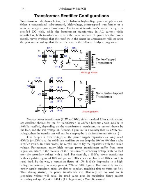
18<strong>Unbalancer</strong> 9-Pin PCBTransformer-Rectifier ConfigurationsTransformers As shown below, the <strong>Unbalancer</strong> high-voltage power supply can useeither a conventional tube-intended, high-voltage, center-tapped transformer or anon-center-tapped power transformer. The topmost transformer’s current rating is inrectified DC yield, while the bottommost transformer, in AC current yield;nonetheless, both transformers deliver the same amount of power for the powersupply. Never overlook that the rectifiers in the center-tap arrangement will see twicethe peak reverse voltage that the rectifiers see in the full-wave bridge arrangement.R17D2R14C8C7R13D1 J9ACCTACCenter-TappedTransformer480Vct @ 130mAR17D1R13C8D2R14ACC7Non-Center-TappedTransformerD3R15J9ACD4R16240Vct @180mAStep-up power transformers (115V to 230V), either standard EI or toroidal core,are excellent choices for the B+ transformer, as 230Vac becomes about 325Vdc to340Vdc rectified, depending on the transformer’s regulation, the current drawn bythe load, and the wall voltage. (Of course, if you live in a country that uses 230V wallvoltage, then the transformer will not be a step-up but a an isolation transformer.)One danger is over voltage, as the power supply capacitors are only rated400Vdc (or 200V) and the solid-state rectifiers do not drop the 10V to 40V that a tuberectifier would. In other words, be careful not to fry the capacitors with too muchvoltage. Furthermore, many high voltage power transformers suffer from poorregulation, which is the measure of the transformer’s secondary voltage with no loadover the secondary voltage with a load. For example, a 100Vac power transformerwith a regulator figure of 10% will put out 110Vac with no load and 100Vac with itsrated load. By the way, a regulation figure of 10% is fairly impressive in a highvoltagetransformer, as many present 20% or 30% figures. Unfortunately for thepower supply capacitors, tubes are slow to conduct, requiring time to warm up first.Thus during startup, the power transformer will effectively see no load, so itssecondary voltage will equal its rated value plus its regulation figure againstsecondary voltage: Vpeak = 1.414 x (1 + Regulation) x Vsec. Be warned.
GlassWare Audio Design 19GroundingThe <strong>Unbalancer</strong> PCB holds a star ground at its center. Ideally, this will be the onlycentral ground in the line-stage amplifier. Ground loops, however, are extremely easyto introduce. For example, if the RCA jacks are not isolated from the chassis, then thetwisted pair of wires that connect the PCB to the jacks will each define a ground loop(as will jumper J9, which bridges the PCB’s ground to the chassis). The solution iseither to isolate the jacks or use only a single hot wire from an input RCA jack toPCB (the wire can be shielded, as long as the shield only attaches at one end). Thus,the best plan is to plan. Before assembling the line-stage amplifier, stop and decidehow the grounding is going to be laid out, then solder.Three different schools of thought hold for grounding a piece of audio gear. TheOld-School approach is to treat the chassis as the ground; period. Every groundconnection is made at the closest screw and nut. This method is the easiest to followand it produces the worst sonic results. Steel and aluminum are poor conductors.The Semi-Star ground method uses several ground “stars” that are often calledspurs, which then terminate in a single star ground point, often a screw on thechassis. This system can work beautifully, if carefully executed. Unfortunately, oftentoo much is included in each spur connection. For example, all the input and outputRCA jacks share ground connection to a long run of bare wire, which more closelyresembles a snake than a spur ground. In other words, the spurs should not bedefined just physical proximity, but signal transference. Great care must be exercisednot to double ground any spur point. For example, the volume control potentiometercan create a ground loop problem, if both of its ground tabs are soldered together atthe potentiometer and twisted pairs, of hot and cold wires, arrive at and leave thepotentiometer, as the two cold wires attaching to the PCB will define a ground loop.The Absolute-Star grounding scheme uses a lot of wire and is the most timeconsuming to layout, but it does yield the best sonic rewards. Here each input signalsource and each output lead gets its own ground wire that attaches, ultimately, at onestar ground point; each RCA jack is isolated from the chassis. The PCB was designedto work with this approach, although it can be used with any approach.House Ground The third prong on the wall outlet attaches to the house’sground, usually the cold water pipe. The line-stage amplifier can also attach to thisground connection, which is certainly the safest approach, as it provides a dischargepath should the B+ short to the chassis. Unfortunately, this setup often produces ahum problem. Some simply float the ground (not safe), others use several solid-staterectifiers in parallel to attach the chassis ground to the house ground (NOTNEUTRAL) via the third prong, and others still use a 10-ohm resistor shunted by asmall capacitor, say 0.001µF to 0.1µF/250V. One last technique might prove the bestsolution: couple the power supply ground to the house ground via a choke. A low-DCR choke will provide a ready DC discharge path and if its inductance is highenough, it will isolate the audio ground from the AC noise present on the houseground.ChassisGroundHouseGroundSignalGround0.01µF250V10