

Unbalancer 9-pin.pdf - Tube CAD Journal
Unbalancer 9-pin.pdf - Tube CAD Journal
Unbalancer 9-pin.pdf - Tube CAD Journal

Create successful ePaper yourself
Turn your PDF publications into a flip-book with our unique Google optimized e-Paper software.
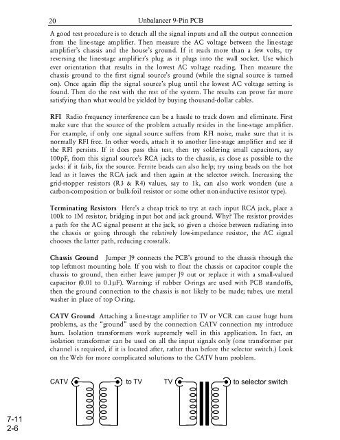
20<strong>Unbalancer</strong> 9-Pin PCBA good test procedure is to detach all the signal inputs and all the output connectionfrom the line-stage amplifier. Then measure the AC voltage between the line-stageamplifier’s chassis and the house’s ground. If it reads more than a few volts, tryreversing the line-stage amplifier’s plug as it plugs into the wall socket. Use whichever orientation that results in the lowest AC voltage reading. Then measure thechassis ground to the first signal source’s ground (while the signal source is turnedon). Once again flip the signal source’s plug until the lowest AC voltage setting isfound. Then do the rest with the rest of the system. The results can prove far moresatisfying than what would be yielded by buying thousand-dollar cables.RFI Radio frequency interference can be a hassle to track down and eliminate. Firstmake sure that the source of the problem actually resides in the line-stage amplifier.For example, if only one signal source suffers from RFI noise, make sure that it isnormally RFI free. In other words, attach it to another line-stage amplifier and see ifthe RFI persists. If it does pass this test, then try soldering small capacitors, say100pF, from this signal source’s RCA jacks to the chassis, as close as possible to thejacks: if it fails, fix the source. Ferrite beads can also help; try using beads on the hotlead as it leaves the RCA jack and then again at the selector switch. Increasing thegrid-stopper resistors (R3 & R4) values, say to 1k, can also work wonders (use acarbon-composition or bulk-foil resistor or some other non-inductive resistor type).Terminating Resistors Here’s a cheap trick to try: at each input RCA jack, place a100k to 1M resistor, bridging input hot and jack ground. Why? The resistor providesa path for the AC signal present at the jack, so given a choice between radiating intothe chassis or going through the relatively low-impedance resistor, the AC signalchooses the latter path, reducing crosstalk.Chassis Ground Jumper J9 connects the PCB’s ground to the chassis through thetop leftmost mounting hole. If you wish to float the chassis or capacitor couple thechassis to ground, then either leave jumper J9 out or replace it with a small-valuedcapacitor (0.01 to 0.1µF). Warning: if rubber O-rings are used with PCB standoffs,then the ground connection to the chassis is not likely to be made; tubes, use metalwasher in place of top O-ring.CATV Ground Attaching a line-stage amplifier to TV or VCR can cause huge humproblems, as the “ground” used by the connection CATV connection my introducehum. Isolation transformers work supremely well in this application. In fact, anisolation transformer can be used on all the input signals only (one transformer perchannel is required, if it is located after, rather than before the selector switch.) Lookon the Web for more complicated solutions to the CATV hum problem.CATVto TVTVto selector switch7-112-6


