Ultra Wideband Radar for Micro Aerial Vehicles - Student Projects
Ultra Wideband Radar for Micro Aerial Vehicles - Student Projects
Ultra Wideband Radar for Micro Aerial Vehicles - Student Projects

Create successful ePaper yourself
Turn your PDF publications into a flip-book with our unique Google optimized e-Paper software.
ContentsAbstractv1 Introduction 12 <strong>Ultra</strong> <strong>Wideband</strong> <strong>Radar</strong> 32.1 Fundamental Principles of an Impulse <strong>Radar</strong> . . . . . . . . . . . . . 42.2 Detection of Objects at Various Distances . . . . . . . . . . . . . . . 52.3 Modulated Pulse Repetition Period . . . . . . . . . . . . . . . . . . . 52.4 Advantages of Impulses . . . . . . . . . . . . . . . . . . . . . . . . . 52.5 State-of-the-Art UWB <strong>Radar</strong> Technology . . . . . . . . . . . . . . . 62.6 Annotation . . . . . . . . . . . . . . . . . . . . . . . . . . . . . . . . 73 Requirements of an UWB <strong>Radar</strong> <strong>for</strong> MAV Applications 93.1 Obstacle Avoidance and Mapping . . . . . . . . . . . . . . . . . . . . 93.2 Requirements . . . . . . . . . . . . . . . . . . . . . . . . . . . . . . . 94 <strong>Radar</strong> Imaging 115 Presence Sensor Approach 135.1 Sensor Array versus Mechanical Positioning . . . . . . . . . . . . . . 135.2 Potential Errors . . . . . . . . . . . . . . . . . . . . . . . . . . . . . . 135.3 Pros and Cons . . . . . . . . . . . . . . . . . . . . . . . . . . . . . . 145.4 Literature . . . . . . . . . . . . . . . . . . . . . . . . . . . . . . . . . 146 Back Projection Algorithm 156.1 Standard Back Projection . . . . . . . . . . . . . . . . . . . . . . . . 156.2 Cross-correlated Back Projection . . . . . . . . . . . . . . . . . . . . 176.3 Results . . . . . . . . . . . . . . . . . . . . . . . . . . . . . . . . . . . 186.4 Pros and Cons . . . . . . . . . . . . . . . . . . . . . . . . . . . . . . 196.5 Literature . . . . . . . . . . . . . . . . . . . . . . . . . . . . . . . . . 197 Image Focusing Algorithm 217.1 Naive Image Focusing Algorithm . . . . . . . . . . . . . . . . . . . . 217.2 Enhanced Image Focusing Algorithm . . . . . . . . . . . . . . . . . . 227.3 “Bat-Type ”Imaging . . . . . . . . . . . . . . . . . . . . . . . . . . . 237.4 Pros and Cons . . . . . . . . . . . . . . . . . . . . . . . . . . . . . . 247.5 Literature . . . . . . . . . . . . . . . . . . . . . . . . . . . . . . . . . 248 Wave Equation Migration 258.1 Kirchhoff Migration . . . . . . . . . . . . . . . . . . . . . . . . . . . 258.2 Phase Shift Migration . . . . . . . . . . . . . . . . . . . . . . . . . . 268.3 Stolt Migration . . . . . . . . . . . . . . . . . . . . . . . . . . . . . . 278.4 Results . . . . . . . . . . . . . . . . . . . . . . . . . . . . . . . . . . . 28iii
Abstract<strong>Ultra</strong> wideband (UWB) technology has become a very popular topic in industryand academia. UWB signals have an excellent spatial resolution and good penetrationinto many materials which makes them very interesting <strong>for</strong> radar applications.This report gives a short introduction to UWB radar and an overview about thestate-of-the-art technology. Further, different imaging algorithms and their potentialemployment on MAVs <strong>for</strong> obstacle avoidance and simultaneous localization andmapping (SLAM) are discussed.Keywords: <strong>Ultra</strong> <strong>Wideband</strong> (UWB), MAV, radar imaging, obstacle avoidancev
Chapter 1IntroductionCurrently, the term <strong>Micro</strong> <strong>Aerial</strong> Vehicle (MAV) refers to an Unmanned <strong>Aerial</strong>Vehicle which are designed to operate in urban canyons or even inside buildings.The definition employed in DARPA’s program limits these aircrafts to a size lessthan 15 cm in length, a weight of 100 g with a possible payload of 20 g [7].MAV have a wide range of potential uses, not only in military applications but theycould also support firefighters and police departments in their work and per<strong>for</strong>mcommercial tasks such as data and image acquisition of disaster areas, map building,communication relays, search and rescue, traffic surveillance and so on.In order to successfully fulfill such operations in urban or even in GPS-denied environmentsrequire fully autonomous flight due to response time limitations in humanpiloting. A commercial breakthrough of MAVs has been constrained so far by thelack of a light-weight, low-power sensor suite which is capable of detecting nearbyobstacles, trigger an evasive maneuver and building a map of its environment.Traditionally, these tasks are per<strong>for</strong>med by heavy laser-rangefinders or clever visionalgorithms are applied. But these methods have their limitations, e.g. in smoky air.Recent advances in micro chip technology and the less restrictive regulations of theFCC have made UWB radar a leading technology candidate <strong>for</strong> MAVs. UWB radarsensors allow high resolution in detection and localization of passive objects in shortrange distance. Nowadays, because of its small size and light weight, a low-powerUWB radar could easily be installed on a MAV and alert it of nearby obstacles.This makes UWB radar a promising alternative <strong>for</strong> autonomous navigation in anunknown environment.1
Chapter 1. Introduction 2
Chapter 2<strong>Ultra</strong> <strong>Wideband</strong> <strong>Radar</strong>RAdio Detection And Ranging (RADAR) devices emit electromagnetic signals.These signals are diffracted and scattered in all directions when they come intocontact with an object. A part of the energy transmitted by the radar gets there<strong>for</strong>ereflected back to radar. By measuring the time between sending the signal andreceiving the echo, the distance to the target can be calculated.Conventional radars work in a narrow frequency band. Old-fashioned radars sendout continuous waves in bursts at a single frequency and simply measure the roundtriptime of the wave. Most modern radar systems are based on frequency modulation(FMCW). They continuously send out an electromagnetic wave, varying thefrequency in a sawtooth pattern. By the time the signals returns to the antenna,the outgoing signal has shifted to a higher frequency. The greater the shift, thelonger the travel time and thus the distance to the object.UWB systems operate in the time domain. Impulse radars send out short pulsesin time and listen to the echo. The distance to the target can be estimated bytiming of the echo arrival. A Fourier trans<strong>for</strong>m shows that a short pulse in timecorresponds to a wide frequency content (Fig. 2.1 and 2.2). The shorter the pulse(till reaching the Dirac’s delta), the wider the frequency spectrum, hence the nameultra wideband.Figure 2.1: A sinusoidally shaped UWB pulse in the time domain. [44]3
Chapter 2. <strong>Ultra</strong> <strong>Wideband</strong> <strong>Radar</strong> 4Figure 2.2: A sinusoidally UWB pulse in the frequency domain (FFT estimate).[44]2.1 Fundamental Principles of an Impulse <strong>Radar</strong>Fig. 2.3 shows the fundamental principles of an impulse radar. A transmitterrepeatedly emits short pulses on a target. In contrast to a conventional radar, thedistance of the target is presumed at the beginning. The receiver only acceptsechoes from objects at a preset distance (radar bubble). This is done by not onlytransmitting the pulse from the generator, but also sending it to a delay line. Thedelay element controls the sampling of the antenna voltage. The antenna voltage isonly measured during a short period. If an echo is received during this short period,an object must be located in the preset range 1 .Figure 2.3: The UWB radar scheme. [5]1 Preset distance is an implementation issue. Because the pulses are so short in time, it is reallyhard to measure the exact time of arrival of a pulse. A high sampling rate would be necessary.
5 2.2. Detection of Objects at Various Distances2.2 Detection of Objects at Various DistancesMore sophisticated UWB radars differ only a few from this very simple radar. Amajor drawback of the scheme shown in Fig. 2.3 is that it is only able to look <strong>for</strong>targets at one certain range. There are two different approaches to overcome this:• By slowly increasing the delay-time after each received pulse, the sensor cansweep through different ranges and detect objects in different shells. Aftersome thousand pulses, the radar can provide a full image of its environment.With high pulse repetition rates, McEwan Technologies is able to sweepthrough a 1m range in 0.025s [32].• Instead of using only one sampler, there are circuits which sample the incomingdata with up to 256 individual sampler, each with another delay time.The radar there<strong>for</strong>e detects objects simultaneously at 256 different ranges. Acomplete overview of its surrounding is provided instantaneously after eachemitted pulse.2.3 Modulated Pulse Repetition PeriodNormally, a noise source is added to the timing circuitry to generate the pulsesrandomly around a frequency of some MHz. This has several advantages comparedto identically distributed pulses:• Interference from other radio services such as TV signals are averaged to zeroby randomizing the sampling.• Several UWB radars can operate close to each other without interfering.• Randomized pulses are hard to detect with conventional radio-frequency receiversand make UWB radar there<strong>for</strong>e stealthy.2.4 Advantages of ImpulsesThere are mainly four reasons why UWB radars are using really short pulses intime:• Short pulses in time automatically induce high resolution and accuracy. Thecounterpart to the wavelength concept in conventional radars is the “pulselength in space”concept.l pulse = τ · c light (2.1)The shorter the pulse, the better the resolution. A spatial resolution of justover 4mm has been achieved by the Novelda Impulse <strong>Radar</strong> which correspondsto a pulse duration of τ = 15ps [4].• Although ranging is straight<strong>for</strong>ward with the radar scheme shown, it becomeschallenging when more realistic situations are considered. The main source oferror is multipath propagation. For most purposes, only the direct path is ofinterest. The excellent resolution of UWB (due to short pulse duration) allowseasy separation of the direct path component and multiple backscatteredwaves in the time domain.• Short pulses have an improved penetration of matter. This is due to the widespectral content of impulses. For a given dimension, it is possible to find afrequency with higher penetration due to resonance. With a wide spectrum of
Chapter 2. <strong>Ultra</strong> <strong>Wideband</strong> <strong>Radar</strong> 6frequencies, it is more likely to hit a resonance frequency than with a narrowband as it is used by conventional radars. Since UWB radars detect incomingenergy of the pulses in time and not at certain frequencies, absorption ofspecific frequencies has little influence on the radar.• In order to comply with the FCC regulations, the energy of the pulses must bevery weak. Since most energy is needed when transmitting a pulse, the shorterthe pulse, the less power is needed to operate an UWB radar. This is of greatimportance when the radar is installed on a mobile plat<strong>for</strong>m like a MAV withlimited battery charge. One type of UWB radars invented at the LawrenceLivermore National Laboratory operates <strong>for</strong> several years on two AA batteries[5]. But low-power pulses imply that the energy measured at the receivingantenna is very weak. There<strong>for</strong>e, many samples must be taken and averagedin order to improve the signal-to-noise ratio and to obtain meaningful results.2.5 State-of-the-Art UWB <strong>Radar</strong> TechnologyAlthough UWB technology is quite popular, there are only a few companies andlaboratories which work on the UWB radar application. Most of them focus oncommunication applications. In Tab. 2.1, in<strong>for</strong>mation about their prototypes islisted if available. Un<strong>for</strong>tunately, some of the companies such as MultispectralSolutions and Eureka Aerospace do not exist anymore or seem to be inactive. Theyare just listed <strong>for</strong> the sake of completeness.Table 2.1: State-of-the-art UWB radar technology. [41]Prototype Center Freq. Resolution Range Bins PhysicalLab, Company Bandwidth Range Power DimensionsNVA 3000 [4]Novelda1.5-3.4GHz-4mm0-15m12850mWsingle chip-MIR [32]McEwan Techn.2.5GHz1GHz15cm50m1m sweep50mW37.5x43mm-RaDeKL [16]Multispectral6.0-6.6GHz0.4GHz30cm345m2561.2W150x83x62mm490gMAVCAS [17]Multispectral6.35GHz0.5GHz30cm20m2560.25mW65x70mm42.5gImpSAR [1]Eureka Aero2GHz3.5GHz5cm100m--110dm 313.6kgPrism 200 [13][12]Cambridge Cons.1.7-2.2GHz0.5GHz30cm20msweep-21x30x45cm3.5kg<strong>Radar</strong>VisionTime Domain3.85GHz3.5GHz5cm10m-50µW--PulsON 400 [14]Time Domain4.3GHz3.1-5.3GHz7cm1000m-10µW-2.5W76x76x10mm-DV9110 [47]Wisair3.1-4.8GHz0.5GHz----40x60mm-- [28]MAI1GHz0.8GHz50cm3m-240µW--In addition to those listed above, the following laboratories/universities are alsoworking in the UWB radar field, but no in<strong>for</strong>mation on their prototypes is available:Defence R&D Canada, TU Illmenau, Johannes Kepler University, Kyoto Universityand Delft University of Technology.
Chapter 2. <strong>Ultra</strong> <strong>Wideband</strong> <strong>Radar</strong> 8
Chapter 3Requirements of an UWB<strong>Radar</strong> <strong>for</strong> MAV Applications3.1 Obstacle Avoidance and MappingThe hardest task <strong>for</strong> a MAV is to operate autonomously in complex environmentssuch as urban population centers with a lot of moving objects. In order to makeintelligent movements and avoid collision, the MAV has to be endowed with enoughsituational awareness. This can be done by acquiring an accurate position estimationrelative to the environment and generate an image of the real world.An obstacle avoidance sensor is absolutely essential <strong>for</strong> MAVs. In the simplestcase, the MAV is just hovering in the open air while another object is approaching.To successfully avoid a potential collision, the direction as well as the remainingdistance to the approaching object have to be known. In most cases however, theMAV cannot fly in an arbitrary direction to avoid the obstacle, <strong>for</strong> instance whenflying in a hallway. It would be an asset if potential alternative paths are knownbe<strong>for</strong>ehand, but this requires a map and the MAVs exact location. If a map ofthe surrounding is available a priori, then the task of localization simply becomesone of trying to correlate the real world with a sensor-generated image and extractits position. If this is not the case, a map has to be be built while flying around(SLAM).3.2 RequirementsTo deal with the tasks stated above, the following requirements arise <strong>for</strong> the employmentof a UWB radar on a MAV [17]:• Weight: Less than 50 grams including antenna array.• Size: Overall antenna array size has to be compatible with MAV vehicleconstraints.• Power: Less than 1 Watt.• Range: A minimum of 15 meters <strong>for</strong> obstacle avoidance. This gives the MAVenough time to trigger an evasive maneuver given an air speed of 10 m s .• Resolution: 10 cm in horizontal resolution. If the radar system is also used asan altimetry support <strong>for</strong> vertical take-off and landing, the resolution should bein the millimeter range. The <strong>Radar</strong> should not only be able to detect objects,but also locate them.9
Chapter 3. Requirements of an UWB <strong>Radar</strong> <strong>for</strong> MAV Applications 10• Update Rate: If only a single sampler is used which has to sweep throughvarious ranges, the update rate should be > 1000 updates per second.• Field of View: Angular Coverage of 360 degrees, due to the fact that mostMAV do not have a specific head and tail, but can fly in all directions.• Computational Cost: Small computational cost to provide real time imagesof the environment.
Chapter 4<strong>Radar</strong> ImagingSo far, the impulse radar introduced only operates as a rangefinder. No furtherin<strong>for</strong>mation about the exact location of a backscattering object is obtained. It isonly known that it lies on a circle with the sensor as center and the measuredrange as radius. To accomplish the task of mapping and obstacle avoidance, usinga single UWB sensor is there<strong>for</strong>e not sufficient. Multiple sensors are necessary toget in<strong>for</strong>mation on the angle relative to the MAV.There are three different approaches to get this in<strong>for</strong>mation:• A narrow beam is used by the UWB radar. The beam is mechanically orelectronically positioned and can be swept over the area of interest. Within<strong>for</strong>mation on the beams direction and the distances to objects surroundingthe radar, a map can be built. Typically, these radars are used on ships.• In<strong>for</strong>mation from several UWB radars, each at a slightly different position, arefused. From the time difference of arrival of several antennas, a good locationestimation can be calculated. The more UWB radars are used, the larger theaperture size and thus the more precise the image of the real world.• Instead of using an array of UWB radars, a large aperture size can also beachieved synthetically. One single UWB radar takes measurements at differentpoints, whose position are known or estimated e.g. by an inertial measurementunit (IMU) or a camera. Fusing these measurements yields to a large syntheticaperture and there<strong>for</strong>e to a map with fine resolution.All approaches have their advantages and disadvantages. Imaging algorithms basedon these approaches are introduced and discussed in the next chapters.11
Chapter 4. <strong>Radar</strong> Imaging 12
Chapter 5Presence Sensor Approach5.1 Sensor Array versus Mechanical PositioningThe easiest way to obtain a range map of objects surrounding the MAV is to sweepan UWB beam over the area of interest. Almost no further signal processing isnecessary to build up a map based on range and direction in<strong>for</strong>mation. However,this method lacks of providing a real-time image due to the delays when the sensoris repositioned and makes it unemployable <strong>for</strong> MAV applications. To keep theadvantage of really low computational costs, MSSI developed a micro air vehiclecollision avoidance sensor (MAVCAS [17]) which operates as a presence sensor. Itonly determines the presence or absence of a target and its distance. To get decentangular resolution, several sensors, each with a narrow beam width, have to beplaced around the MAV. This way, the MAV does not have to face in a certaindirection <strong>for</strong> flying around but is aware of the whole 360 degrees flight space. Asimilar approach has been applied to a quadrotor by Roberts [33] and Beecher [6].In [33], they used four infrared distance sensors <strong>for</strong> indoor hovering and collisionavoidance. Beecher and collaborators used sensors with different beam widths.5.2 Potential ErrorsThe width of the beam determines both the range and angular resolution. Sincethe width is not infinitesimally small, two different errors can occur.• If the sensor is not placed perpendicular to the surface of a flat target, therange is not measured exactly (Fig. 5.1). For complex surfaces, the problembecomes even more complicated.Figure 5.1: Range errors occur if the incidence angle is not perpendicular. [29]13
Chapter 5. Presence Sensor Approach 14(a)(b)Figure 5.2: At a distance where the beam is wider than a door opening (b), theopening is not discernible <strong>for</strong> the radar system. [29]• The UWB radar cannot distinguish two objects by their cross-section. Forinstance, a narrow vertical pole appears to the sensor in exactly the same waythan a wall located at the same distance. As a consequence, openings in awall such as a door might not be recognized if the beam is wider than thedoor frame (Fig. 5.2).5.3 Pros and ConsProsCons• Real time imaging.• Low computational cost.• Dynamic targets can be detected.• Low range and angular resolution.• A lot of sensors are necessaryto cover 360 degrees flight spacewith a reasonable resolution.• A mechanically or electrically positionedbeam has a slew time delay.5.4 Literature• Fontana et al. An <strong>Ultra</strong> <strong>Wideband</strong> <strong>Radar</strong> <strong>for</strong> <strong>Micro</strong> <strong>Aerial</strong> Vehicle Applications.2002 [17]• Jackson et al. <strong>Ultra</strong>sonics and Robotics. 1997 [29]• Roberts et al. Quadrotor Using Minimal Sensing <strong>for</strong> Autonomous IndoorFlight. 2007 [33]• Beecher et al. Virginia Tech Entry to the 2009 International <strong>Aerial</strong> RoboticsCompetition. 2009 [6]
Chapter 6Back Projection AlgorithmA simple method <strong>for</strong> reconstructing radar images is the back projection method,also called diffraction summation and commonly used in the field of medical imagingand spotlight-SAR. For this time-reversal algorithm, an array of receiving antennasis used and a range profile <strong>for</strong> each is <strong>for</strong>med. A 2-D radar image of the targetfield can be reconstructed by summing of the range profiles. The standard backprojection algorithm works well <strong>for</strong> short ranges relative to the overall aperturesize. For large distances, the algorithm tends to produce smear images. To remedythis problem, the cross-correlated back projection algorithm correlates the rangeprofiles with the profile of a reference channel.6.1 Standard Back ProjectionA set of N receiving elements are arranged in a linear array, equally spaced withan inter-element spacing d. Given a signal function f(t) radiated by a transmitterlocated at (x t , y t ), the total signal s(t) at distance R and incidence angle θ can beexpressed as a convolution of the signal f(t) with the near-field impulse responseh(t) of the array:s(R, θ) =∫ ∞−∞f(t)h(t − τ)dτ (6.1)The near-field impulse response can be expressed as a sum of N delta functions:h(t − τ) =N−1∑n=0δ(t − τ), where τ = t T x + 1 (R + nd sin θ + ∆r) (6.2)cThis follows directly from Fig. 6.1, where N is the total number of receivers, c thespeed of light, t T x = R t /c the transmitter propagation delay and ∆r the near-fieldcorrection factor <strong>for</strong> the n-th element. ∆r can be represented by:1∆r = r − r // = (R + nd sin α) · ( − 1) (6.3)cos βThe back projected signal in terms of the distance R and the scan angle θ is givenby substituting Eq. 6.2 into 6.1:s(R, θ) =N−1∑n=0f(t n ), where t n = t T x + 1 (R + nd sin θ + ∆r) (6.4)cThe function f(t n ) is the range profile of the n-th array element. By varying theincidence angle θ of a range profile, f(t n ) represents a path that <strong>for</strong>ms the n-th15
Chapter 6. Back Projection Algorithm 16Figure 6.1: Near-field array response. [19]point response <strong>for</strong> a target located at distance R. Each point response has a slightlydifferent shape. They intercept only at the target location. The sum of all thesepoint responses <strong>for</strong>ms the impulse response of the radar image. A coherent sum isonly <strong>for</strong>med where point responses of different elements intersect.To sum up, the position of an object can be estimated by using an antenna array incombination with the back projection algorithm. The distance from each antennato the object is measured. The back projection method then sums up the rangeprofiles of each antenna element (Fig. 6.2 and Eq. 6.4). The exact echo wave<strong>for</strong>mdoes not necessarily have to be known.Figure 6.2: Antenna array and back projection technique. [20]
17 6.2. Cross-correlated Back ProjectionA main drawback of this algorithm is, that each of these point responses smears thebeam pattern of the image in the azimuth direction. The larger the distance of thetarget to the array center, the worse the smearing distortion (Fig. 6.3).Figure 6.3: Cross-range resolution ∆X <strong>for</strong> triangulation based algorithms. [48]6.2 Cross-correlated Back ProjectionTo solve the problem of smearing distortion, the correlation of the receiver channelswith a reference channel is proposed by [19]. Preferably, the reference point responseis measured away from the center of the receiving array. The best results areobtained if the reference point response is orthogonal to all other point responses.The cross-range resolution is then determined by the UWB pulse length in space.The near-field intra-pulse cross-correlated signal function p can then be computedas:M∑p(R, θ) = f(t ref ) · s(R, θ), where t ref = t T x + t Rx + i · T (6.5)i=0M is the total number of sample points in the UWB pulse, T is the sampling period,t Rx is the propagation delay from the target to the reference receiver and f(t ref )represents the range profile of the reference channel. In [51], a modification of thecross-correlated back projection algorithm is proposed. This modified algorithmexploits a further reference antenna.p(R, θ) =M∑f 1 (t ref1 ) · f 2 (t ref2 ) · s(R, θ) (6.6)i=0
Chapter 6. Back Projection Algorithm 186.3 ResultsThe cross-correlating back projection method has been applied <strong>for</strong> through-wallimaging by Defence R&D Canada. The test setup is shown in Fig. 6.4 and [19]. Inthis experiment, the center element of the antenna array was taken as the referencechannel.Figure 6.4: Layout of the indoor through-wall imaging test setup. [19]Figure 6.5: Measured 2D radar image. [19]Fig. 6.5 shows the reconstructed image using the cross-correlation back projectionmethod. The modified cross-correlated back projection has even demonstratedbetter per<strong>for</strong>mance in numerical examples [51].
19 6.4. Pros and Cons6.4 Pros and ConsProsCons• Instant imaging.• High resolution of nearby objects.• Easily adaptable to different arrayconfigurations. Also workingwith synthetic aperture.• Low cross-range resolution.• Target shape not recognizable.• Produces a lot of artefacts.• Requires big computation power.• SAR only operates as a sidelookingradar and no dynamic objectsare detectable.• Cross-correlated back projectionis hard to apply to a MAV.6.5 Literature• Senglee et al. <strong>Ultra</strong>-wideband (UWB) Remote Sensing and <strong>Radar</strong> Imaging.2004 [19]• Senglee et al. Cross-correlated back projection <strong>for</strong> UWB radar imaging. 2004[18]• Zetik et al. Modified Cross-Correlation back Projection <strong>for</strong> UWB Imaging:Numerical Examples. 2005 [51]• Aftanas et al. Through Wall Imaging of the Objects Scanned by M-sequenceUWB <strong>Radar</strong> System. 2008 [3]• Nguyen et al. Obstacle Avoidance and Concealed Target Detection Using theArmy Research Lab <strong>Ultra</strong>-<strong>Wideband</strong> Synchronous Impulse Reconstruction(UWB SIRE) Forward Imaging <strong>Radar</strong>. 2007 [15]• Yarovoy et al. UWB Array-Based Sensor <strong>for</strong> Near-Field Imaging. 2007 [50]• Aftanas. Through Wall Imaging with UWB <strong>Radar</strong> System. 2009 [2]• Gauthier et al. Through-The-Wall Surveillance. 2002 [20]
Chapter 6. Back Projection Algorithm 20
Chapter 7Image Focusing AlgorithmThis imaging algorithm is very similar to back projection. Both algorithms makeuse of the well-known triangulation approach in order to estimate the target positionin a 2-D plane. This processing technique is simpler however, it only uses a twoelementRx array and does not calculate the range profiles. A pulse is emitted ata transmitting antenna and the response is collected with a delay time τ at thereceiving antenna. All potential backscattering points which corresponds to themeasured delay τ lie on an ellipse around the transmitting and receiving antenna.Taking another measurement at a slightly different position yields to a second ellipse.The reflecting object has there<strong>for</strong>e to be at the position where the two ellipses arecrossing.Figure 7.1: Imaging of the environment.7.1 Naive Image Focusing AlgorithmThe set-up is shown in Fig. 7.2a with one target to be imaged based on receivedwave<strong>for</strong>ms at a linear array.A grid of pixels is laid over a given horizontal field of view, bounded by the minimumand maximum distance as well as an angular extent. The number of pixels is definedby the range resolution capabilities of the UWB radar. A pulse is emitted by Tx.The received signals at the two Rx channels are then shifted in time to equalizedelays <strong>for</strong> each pixel with respect to its location (i, j). The brightness of a pixel21
Chapter 7. Image Focusing Algorithm 22Figure 7.2: (a) <strong>Radar</strong> scene <strong>for</strong> imaging with array. (b) <strong>Radar</strong> field of view sceneas a numerical map of pixels. [9](i, j) is <strong>for</strong>med by computing the windowed correlation of equalized signals. Theintensity I of a pixel, to which the received signals are focused is thus given by:where:∫I i,j =T Ws 1(2),ij (t) = S 1(2) (t − D0cW (t) · s 1,ij (t) · s 2,ij (t)dt (7.1)− D i,j1(2)) (7.2)c• W (t) is an appropriate weighting and time-domain windowing function.• T W is an appropriate time gate <strong>for</strong> averaging over each pixel, e.g. the transmitpulse width.• S1 and S2 are the signals received at the two radar channels.• D1 and D2 are the distances from the focusing point (i, j) two the receivers1 and 2.• c is the speed of light.7.2 Enhanced Image Focusing AlgorithmTypically, background scattering makes it hard to <strong>for</strong>m clear images. If one is onlyinterested in tracking dynamic objects, static objects such as walls can be removedby remembering the background scattering first and then subtracting it from thecurrent scattering pattern each time be<strong>for</strong>e a new image is generated. In this changedetector mode, the breathing of a hidden person is easily detectable.Other difficulties appear when trying to <strong>for</strong>m a focused image if the two receivingantennas are close together. The interferometer base is then very small and causessmeared images in the angular direction (cross-range). At the cost of extra computationalresources, this can be improved by applying further processing algorithmsto detect the brightest spots.
23 7.3. “Bat-Type ”Imaging7.3 “Bat-Type ”ImagingThe field of view <strong>for</strong> the bi-static radar system in Fig. 7.2 is fairly small. If thisradar is mounted on a MAV, one can take advantage of the fact that it is movedaround. Thomä and collaborators proposed a bat-type imaging approach similarto echolocation to produce partial maps of the environment with improved quality[46][40].(a) Scanning of an object by a bat-type sensoralong an arbitrary track.(b) Image focusing by stacked averaging of correlatedimage snapshots. The upper figure demonstratesthe shift and rotation operation to achievethe best match of image details.Figure 7.3: Investigating an object in more detail by bat-type imaging. [46]The MAV, in this case corresponds to a bat, flies around and obtains radargramsat different locations (Fig. 7.3a). The radargrams have a low cross-range resolution(because of the short antenna baseline) and a high range resolution (due to theshort pulses). By fusing images taken from different angles and locations, a sharperimage can be generated. The individual images have to be appropriately shifted,rotated and stacked to obtain a focused image (Fig. 7.3b). To achieve this, thebat’s direction and position have to be known. One possibility is to get thesein<strong>for</strong>mation from an IMU or a camera. Another idea is based on self adjusting orauto-focusing. If a dominating backscattering object is present, it can be used asa landmark <strong>for</strong> auto-focusing. The images are stacked and averaged in a way thelandmark experiences the best focus. If the objects are clear enough, no specificknowledge of the track is required and a large map can be built.
Chapter 7. Image Focusing Algorithm 247.4 Pros and ConsProsCons• Depending on the pixel map densityand scene size, little computationalresources are needed.• Dynamic objects can be detected.• Provides an instant image.• Low cross-range resolution.• Tends to produce a lot of artefacts.• Estimate of MAV’s positionneeded <strong>for</strong> bat-type imaging.• Actual wave<strong>for</strong>m has to beknown.7.5 Literature• Boryssenko et al. Portable Imaging UWB <strong>Radar</strong> System with Two-ElementReceiving Array. 2007 [9]• Sostanovsky et al. UWB <strong>Radar</strong> Imaging System with Two-Element ReceivingArray Antenna. 2005 [42]• Sostanovsky et al. Imaging Capabilities of <strong>Ultra</strong>-<strong>Wideband</strong> <strong>Radar</strong> Systemwith Small Receiving Array Antenna. 2005 [43]• Thomä et al. UWB Sensor Networks <strong>for</strong> Position Location and Imaging ofObjects and Environments. 2007 [46]• Seitz et al. UWB Feature Localization <strong>for</strong> Imaging. 2008 [40]
Chapter 8Wave Equation MigrationThe two algorithms introduced in section 6 and 7 are computationally expensive.They are based upon a geometrical approach and do not take into account thewave equation. A similar approach is used in backpropagation methods such asthe Kirchhoff Migration, which are based on solving scalar wave equation. Themigration problem can also be solved in the frequency domain by Fourier Trans<strong>for</strong>m(Stolt Migration). These methods are very fast with low computational complexity.8.1 Kirchhoff MigrationThis algorithm can be easily derived using first principles starting with the scalarwave equation [39]:∇ 2 u(r, t) − 1 ∂ 2 u(r, t)ν 2 ∂t 2 = 0 (8.1)In Eq. 8.1, u is the voltage, r the coordinate and ν the propagation speed. Thesolution to this can be found based on the exploding reflector model (ERM) (Fig.8.1b). It is assumed that instead of the antenna, the target itself is the source. AtFigure 8.1: Measurement setup: a) real scenario, b) thought experiment. [23]time t = 0, the target is “exploding ”. An electromagnetic wave front is radiated25
Chapter 8. Wave Equation Migration 26from the object plane with half actual propagation speed according to Eq. 8.1. Thesolution is then given byu(r ′ , t) = 1 ∫∫ cos φ ∂(r,2π νR ∂t u t + 2R ν)dxdy| t=0 (8.2)where φ denotes the angle between the range axis and the line joining the migratedpoint r ′ and data acquisition point r and R is the distance between these points[52]. The ERM model prohibits the application of the the Kirchhoff integral (Eq.8.2) to mono-static radar system. A modification of Eq. 8.2 is there<strong>for</strong>e needed toadapt Kirchhoff migration to array-based radar systems. For a bi-static radar, themodified Kirchhoff <strong>for</strong>mulation can then be expressed as:∫∫u(r ′ , t) =(cos φ 1 + cos φ 2 ) R 1R 2ν(∂∂t u r, t + R )1 + R 2dxdy| t=0 (8.3)νFigure 8.2: Multi-static configuration indicating geometric angles between rangedirection and transmitting antenna 1 and receiving antenna 2 respectively. [52]8.2 Phase Shift MigrationThe basis of the Phase Shift Migration is again the ERM (Fig. 8.1b). The PhaseShift Migration operates in the frequency - wave number - domain by applyingFourier Trans<strong>for</strong>m. This converts space coordinates into wave numbers and timeinto frequency. For the two-dimensional case as seen in Fig. 8.1a, the solution canbe written asu(x, z, t) =∫ ∞∫ ∞U(k x , z, f) · e j2π(f·t−kx·x) dfdk x (8.4)−∞ −∞using the Inverse Fourier Trans<strong>for</strong>m. Inserting Eq. 8.4 into Eq. 8.1 yields to theone-dimensional wave equation:( (∂ 2 U(k x , z, f)∂z 2 + 2π f ) )2− (2πk x ) 2 · U(k x , z, f) = 0 (8.5)ν
27 8.3. Stolt MigrationThe solution of the wave equation is given by the equationU(k x , z, f) = U(k x , z = 0, f) · e j √(2πfν ) 2 −(2πk x) 2·z(8.6)The first factor represents the boundary condition which is measured by the antennaarray. Inserting this into Eq. 8.4 gives the final solution:u(x, z, t = 0) =∫ ∞∫ ∞−∞ −∞U(k x , z = 0, f) · e j √(2πfν ) 2 −(2πk x) 2·z · e −j2πkx·x dfdk x (8.7)A complete derivation can be found in [11]. The main drawback of this method is,that only the integral over the wave number can be computed by the inverse FastFourier Trans<strong>for</strong>m (IFFT). The integral over the frequency has to be converted intoa summation which costs a lot of calculation time.8.3 Stolt MigrationWith a variable trans<strong>for</strong>mation from the frequency f to the wavenumber k z , thedrawbacks of the Phase Shift Migration can be eliminated.√ (2π f νk z = j) 2− (2πk x ) 2f = k · ν = √ k 2 x + k 2 z and df =k z√k2 x + k 2 zInserting this trans<strong>for</strong>mation into the Phase Shift Migration gives the Stolt Migration[45].u(x, z, t = 0) =∫ ∞∫ ∞−∞ −∞k zU(k x , z = 0, k z )· √ ·e j2πkz·z ·e −j2πkx·x dk z dk x (8.8)k2 x + kz2In Eq. 8.8, both integrals can be computed by the two-dimensional IFFT whichresults in a lower computation time compared to the Phase Shift Migration.
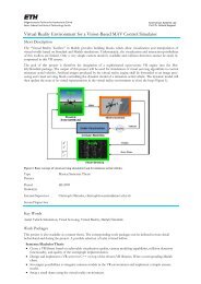
Chapter 8. Wave Equation Migration 288.4 ResultsHantscher and collaborators applied different UWB imaging algorithm to a throughwallscenario to compare their potential <strong>for</strong> identifying targets by their surface shape[24][23]. The measurement setup is briefly described in Fig. 8.1a and Fig. 8.3a.(a) Geometrical layout of the test scenario.(b) Received data from the B-scan.Figure 8.3: Test scenario and the received signal. [24]The radar system emits pulses with a duration of 37ps. The two antennas aremoved along the wall while scanning the target. The result is a two-dimensionalimage of the B-scan (Fig. 8.3b). Fig. 8.4 1 shows the drawback of these conventionalmigration algorithms which reconstruct images by solving the wave equation. Thedashed lines represent the surface of the wall and the circle. The results of theKirchhoff, Phase Shift and Stolt Migration are all very similar because they baseon the same mathematical model (ERM). Stolt Migration however, has shown tobe superior in terms of calculation time compared the the Kirchhoff and PhaseShift Migration. The bright area located at a downrange of 0.47m in Fig. 8.4a-crepresents the cylinder. However, the circular shape can not be identified by any ofthe three algorithms.1 Fig. 8.4d will be discussed in the next chapter, after the IBST is introduced.
29 8.4. Results(a) Result of the Kirchhoff Migration.(b) Result of the Phase Shift Migration.(c) Result of the Stolt Migration.(d) Result of the IBST.Figure 8.4: Reconstructed images with different algorithms.
Chapter 8. Wave Equation Migration 308.5 Pros and ConsSince all three wave equation migration algorithms provide very similar imagingresults but Stolt Migration needs the least computational power, advantages anddisadvantages are only listed <strong>for</strong> the Stolt Migration.ProsCons• Higher quality and less artefactsthan back projection.• Short calculation time.• Applicable to coherent and noncoherentmeasurements.• Target shape not recognizable.• Hard to apply to different sensorconfigurations or synthetic apertureother than straight lines.• Dynamic Objects can be detectedand if a real aperture is used.8.6 Literature• Schneider. Integral Formulation <strong>for</strong> Migration in Two and Three Dimensions.1978 [39]• Hantscher et al. Analysis of Imaging <strong>Radar</strong> Algorithms <strong>for</strong> the Identificationof Targets by Their Surface Shape. 2006 [23]• Hantscher et al. Comparison of UWB Target Identification Algorithms <strong>for</strong>Through-Wall Imaging Applications. 2006 [24]• Zhuge et al. UWB Array-Based <strong>Radar</strong> Imaging Using Modified KirchhoffMigration. 2008 [52]• Bleistein. Hagedoorn told us how to do Kirchhoff migration and inversion.2008 [8]• Cobb et al. Omega-k Quadtree UWB SAR Focusing. 2001 [11]• Stolt. Migration by Fourier Trans<strong>for</strong>m. 1978 [45]• Braga et al. An <strong>Ultra</strong>-<strong>Wideband</strong> <strong>Radar</strong> System <strong>for</strong> Through-the-Wall Imagingusing a Mobile Robot. [10]
Chapter 9Target Shape EstimationAlgorithm Based onBoundary ScatteringTrans<strong>for</strong>mAlgorithms making use of summation such as migration procedures and back projectionare not applicable <strong>for</strong> the identification of targets by their shape. Furthermore,the calculation time excludes them from real-time applications. To overcome this,Sakamoto et al. proposed a time efficient surface estimating imaging algorithmknown as SEABED (Shape Estimation Algorithm based on BST and Extraction ofDirectly scattered waves), using a reversible trans<strong>for</strong>m between the target shape andthe observed data. The main characteristic of this algorithm is that the estimatedtarget is not expressed as an image but lines.The algorithm uses the synthetic aperture principle. An object is scanned fromdifferent viewing angles and the round-trip times of the echoes are determined ateach antenna position. They are then converted into the distance from the target tothe radar and merged to quasi wavefronts (QWF). An inverse boundary scatteringtrans<strong>for</strong>m (IBST) is then applied to the QWF resulting in the surface describingthe target contours.9.1 Direct Scattering ProblemFor simplicity, the reconstruction algorithm is explained in the following sections<strong>for</strong> the 2-D problem, but can easily be extended to estimate 3-D shapes. The setupis shown in Fig. 9.1. It is assumed that the target surface is given by a functiony = f(x) and the scanning antenna is moving along the x-axis. Each transmittedpulse is reflected at the target surface. The primary return occurs at those pointswhere the ray from the transmitter/receiver is normal to the reflecting surface.Using the relationship between the antenna position (X, 0) and the scattering center(x, y) , the round-trip time between the target and the antenna is proportional to:Y = (y 2 + l x ) 0.5 (9.1)It is obvious that X = x + l x and tan ϕ x = l x /y = dy/dx. Solving this <strong>for</strong> l xgives the boundary scattering trans<strong>for</strong>mation (BST) of the surface shape to the31
Chapter 9. Target Shape Estimation Algorithm Based on Boundary ScatteringTrans<strong>for</strong>m 32Figure 9.1: The antenna is scanning the target surface shape while moving alongthe x-axis. [36]2-dimensional QWF:X = x + y · dy(9.2)√dx( ) 2 dyY = y 1 +(9.3)dxFigure 9.2: An example of boundary scattering trans<strong>for</strong>m. [36]Fig. 9.2 shows an example of BST. The left figure shows the target surface in thereal space and the right figure its corresponding QWF.9.2 Inverse Scattering ProblemFor surface reconstruction, Eq. 9.3 has to be inverted in order to estimate thesurface. Since only the round-trip-times of the echoes can be measured, but nothingis know about the angle of arrival, the surface point (x, y) has to lie on a circle with
33 9.3. Modifications and Extensionradius Y and center X.C X (x, y) = (x − X) 2 + y 2 − Y 2 = 0 (9.4)Scanning along the x-axis yields there<strong>for</strong>e to a set of circles in terms of X. Theenvelope of Eq. 9.4 describes the desired target shape, which is calculated as follows:dC X (x, y)dX= 0, there<strong>for</strong>e x = X − Y · dYdX(9.5)Inserting the right side of Eq. 9.5 into 9.4 yields to:√( ) 2 dYy = Y 1 −(9.6)dXBy applying the inverse boundary scattering trans<strong>for</strong>m (IBST) given by Eq. 9.5and Eq. 9.6 to a QWF (X, Y ), the surface can be reconstructed. Thus, in a firststep, QWFs have to be extracted from the measured radar signal. If the scatteringsurface is not smooth (edge points), the task of QWF estimation and extractionfrom received data is very hard. In [36], techniques to deal with these problems areintroduced.9.3 Modifications and ExtensionVarious extensions and modifications are proposed to improve SEABED’s per<strong>for</strong>mance:• For multiple or complex-shaped targets, scattered signals can interfere whichmakes it difficult to estimate the QWFs accurately. In [25] and [35], extendedSEABED algorithms are proposed to extract QWF from received data whicheven work with multiple and complex-shaped targets. The algorithm proposedby Hantscher and collaborators has even been successfully applied to throughwallimaging [25].• The SEABED algorithm was developed <strong>for</strong> using a mono-static radar system.For generating a 3-D image, the antenna has to scan on a plane whichrequires a long time. Moreover, the resolution is limited to the sampling number.To overcome these difficulties, Sakamoto et al. developed a reversibletrans<strong>for</strong>m <strong>for</strong> a bi-static antenna [30]. By numerical simulation, this methodhas shown a much higher resolution than the conventional SEABED methodin 3-D imaging.• The conventional SEABED algorithm only gives good results in noiseless environments.If noise is present, the image is degraded because QWFs cannotbe accurately estimated anymore. To lower estimation errors, a fractionalIBST (FIBST) is proposed to the QWF extraction process in [38] and [37].Experiments show that this method maintains tracking data even in noisyenvironments.9.4 ResultsThe same experiment as in section 8.4 was per<strong>for</strong>med with this algorithm. Theresults are shown in Fig. 8.4d. The reconstructed shape matches well with the realone. The SEABED algorithm only maps the object contour. It does not calculateany intensities <strong>for</strong> every single points. This reduces the amount of data which hasto be processed drastically and there<strong>for</strong>e the SEABED algorithm is even faster thanStolt Migration.
Chapter 9. Target Shape Estimation Algorithm Based on Boundary ScatteringTrans<strong>for</strong>m 349.5 Pros and ConsProsCons• Applicable to mono-static radarsystems.• Extensible to linear array antennas.• Low computational cost.• Good object identification capability.• Continuous expansion of map.• 3-D imaging with mono-staticradar system requires a lot oftime.• Not executable <strong>for</strong> moving targets.As with every SAR algorithm,incoherent measurementsare taken. Fast moving objectscan there<strong>for</strong>e not be imaged.• Only works <strong>for</strong> side-lookingradars. A <strong>for</strong>ward-looking radarwould require a large antennaarray.9.6 Literature• Sakamoto et al. A Target Shape Estimation Algorithm <strong>for</strong> Pulse <strong>Radar</strong> SystemsBased on Boundary Scattering Trans<strong>for</strong>m. 2004 [36]• Hantscher et al. Through-Wall Imaging With a 3-D UWB SAR Algorithm.2008 [25]• Kidera et al. A High-Resolution 3-D Imaging Algorithm with Linear ArrayAntennas <strong>for</strong> UWB Pulse <strong>Radar</strong> Systems. 2006 [30]• Sakamoto et al. Estimation Method of Quasi-wavefronts <strong>for</strong> UWB <strong>Radar</strong>Imaging with LMS Filter and Fractional Boundary Scattering Trans<strong>for</strong>m.2008 [38]• Sakamoto et al. A High-Resolution Imaging Algorithm <strong>for</strong> Complex-ShapedTarget Shapes by Optimizing Quasi-Wavefronts. 2008 [35]• Sakamoto et al. A Stable and Fast 3-D Imaging Algorithm <strong>for</strong> UWB Pulse<strong>Radar</strong>s with Fractional Boundary Scattering Trans<strong>for</strong>m. 2006 [37]• Kidera et al. An Accurate Imaging Algorithm with Scattered Wave<strong>for</strong>m Estimation<strong>for</strong> UWB Pulse <strong>Radar</strong>. 2006 [31]
Chapter 10Further Applications10.1 Human Being DetectionA potential task <strong>for</strong> MAVs is to support rescue operations with data of the disasterarea. An UWB radar can then not only be used <strong>for</strong> collision avoidance but also <strong>for</strong>the detection of human beings trapped in collapsed buildings. A main feature of ahuman is its time variance. Heart beating and respiratory motions cause changes infrequency, phase, amplitude and arrival time of the reflected electromagnetic wave,even if the person is not moving. There are several methods to use these properties<strong>for</strong> human being detection. One has already been mentioned in section 7.2. Dynamicobjects can be detected in static measurements by background subtraction. Signalresponse from static objects is then vanished and only the dynamic response suchas chest moving remains. Due to the fine resolution, UWB radar cannot only detectand locate people but can even be used <strong>for</strong> remote measurements of a persons vitalactivity such as heart-beating and respiration (Fig. 10.1).Figure 10.1: Human respiratory activity from radar returns with background subtraction.[46]10.2 Communication SystemAlthough UWB radio is an old technology and has been used <strong>for</strong> military applications<strong>for</strong> several decades, UWB communications-related applications were intro-35
Chapter 10. Further Applications 36duced only in the early 1990s. The wide bandwidth of UWB allows low-power,low-interference and high data rate communications. Since take-off weight is verycrucial to MAVs, it would be very practical to use the UWB radar also <strong>for</strong> communicationpurposes and not to have an additional communication device whichwould increase the MAVs weight, size and cost. Saddik and collaborators developeda multifunctional UWB communications/radar system. With their system, itis possible to simultaneously explore the environment and communicate through ashared transmitting antenna aperture.10.3 LiteratureHuman Being Detection:• Immoreev. Practical Applications of <strong>Ultra</strong>-<strong>Wideband</strong> <strong>Radar</strong>s. 2006 [27]• Immoreev et al. <strong>Ultra</strong>-<strong>Wideband</strong> (UWB) <strong>Radar</strong> <strong>for</strong> the Remote Measuring ofMain Parameters of Patient’s Vital Activity. 2002 [26]• Yarovoy et al. UWB <strong>Radar</strong> <strong>for</strong> Human Being Detection. 2008 [49]• Thomä et al. UWB Sensor Networks <strong>for</strong> Position Location and Imaging ofObjects and Environments. 2007 [46]• Boryssenko et al. Portable Imaging UWB <strong>Radar</strong> System with Two-ElementReceiving Array. 2007 [9]Communication System:• Saddik et al. <strong>Ultra</strong>-<strong>Wideband</strong> Multifunctional Communications/<strong>Radar</strong> System.2007 [34]
Chapter 11ConclusionUWB technology is very promising. It has many advantages over conventionalrange finding methods. UWB radars are very small in size, low-cost, low-power andhave an excellent range resolution. Although most current UWB radars are onlyprototypes, there are already UWB radars implemented on a single chip. For thepurpose of obstacle avoidance and generating maps of the environment, a varietyof imaging algorithms <strong>for</strong> UWB radar exist. However, most algorithms make use ofthe SAR principle and work there<strong>for</strong>e only as side-looking radars. This makes themuseless <strong>for</strong> MAV applications. On the other hand, real aperture radars which use anantenna array are heavier and worse in terms of resolution. Thomä and collaboratorsproposed a bat-type imaging approach with a bi-static radar to create partial maps,which are then stacked to create a bigger maps with improved quality. Furthermore,by using a real aperture, the radar can not only be used <strong>for</strong> mapping but also <strong>for</strong> thedetection of dynamic objects such as human beings and measure their vital signs.In addition, it can act simultaneously as a radar and communication device.Although the results are not sufficient <strong>for</strong> SLAM, UWB technology is still a veryinteresting technology <strong>for</strong> MAV applications. Because of its fine resolution and fasttravelling 1 signals, it is an excellent alternative to ultrasound rangefinders, whichare often used <strong>for</strong> obstacle avoidance.1 Electromagnetic waves travel in air close to speed of light. This enables UWB rangefinders tomeasure long distances.37
Chapter 11. Conclusion 38
Chapter 12OutlookBat-type imaging and SEABED seem both to be very promising, but none of themcomplies with the requirements <strong>for</strong> MAV applications. Bat-type imaging requirestoo much calculation time <strong>for</strong> real-time evaluation. This circumstance can be solvedby the SEABED algorithm which has shown to be superior in terms of calculationtime and object shape recognition. However, it lacks of a <strong>for</strong>ward-looking image.An interesting project would be to implement a hybrid aperture radar on a MAV.Imaginable would be a MAV with UWB sensor located at all 4 corners. On eachside, two sensor build up a real aperture that allows a quick look at the scene ahead.The radar can still take advantage of its movement by continuously collecting allmeasured data from the sensors on each side. This way, a horizontal two-dimensionalsynthetic aperture is <strong>for</strong>med and can be used to generate a map with the SEABEDalgorithm.Furthermore, investigation about UWB antennas, which determine much of thedevice’s operating characteristics, would be very interesting since it has not beendone at all in this work.39
Chapter 12. Outlook 40
Bibliography[1] Eureka Aerospace. ImpSAR Technology - Technology Description. [online].http://eurekaaerospace.com/impsar.php (as visited on Nov 2009).[2] M. Aftanas. Through Wall Imaging with UWB <strong>Radar</strong> Systems. PhD thesis,Technical University of Kosice, Aug 2009.[3] M. Aftanas, E. Zaikov, M. Drutarovsky, and J. Sachs. Throughwall imaging ofthe objects scanned by M-sequence UWB radar system. In Radioelektronika,2008 18th International Conference, pages 1–4, April 2008.[4] Novelda AS. NVA 3000. [online]. http://www.novelda.no/?page id=598 (asvisited on Nov 2009).[5] S. Azevedo and T. E. McEwan. <strong>Micro</strong>power Impulse <strong>Radar</strong>. Potentials, IEEE,16(2):15–20, Apr/May 1997.[6] Ph. Beecher, A. Franklin, J. Gassaway, A. Oberste, and J. Wright. VirginiaTech Entry to the 2009 International <strong>Aerial</strong> Robotics Competition, 2009.[7] M. Bento. Unmanned <strong>Aerial</strong> <strong>Vehicles</strong>: An Overview. InsideGNSS, pages 54–31,Jan/Feb 2008.[8] N. Bleistein. Hagedoorn told us how to do Kirchhoff migration and inversion.The Leading Edge, 18(8):918–927, 1999.[9] A. O. Boryssenko, D. L. Sostanovsky, and E.S. Boryssenko. Portable ImagingUWB <strong>Radar</strong> System with Two-Element Receiving Array. In <strong>Ultra</strong>-<strong>Wideband</strong>Short-Pulse Electromagnetics 8, pages 153–160, 2007.[10] J. Braga and C. Gentile. An <strong>Ultra</strong>-<strong>Wideband</strong> <strong>Radar</strong> System <strong>for</strong> Through-the-Wall Imaging using a Mobile Robot.[11] M. C. Cobb and J. H. McClellan. Omega-k quadtree UWB SAR focusing. In<strong>Radar</strong> Conference, 2001. Proceedings of the 2001 IEEE, pages 311–314, 2001.[12] Cambridge Consultants. Always wanted x-ray vision? [online], 2006.http://www.cambridgeconsultants.com/downloads/interface/40/x ray vision.pdf(as visited on Nov 2009).[13] Cambridge Consultants. Smart through-wall radar gives new tactical advantagesto police, special <strong>for</strong>ces and emergency services. [online], Nov 2006.http://www.cambridgeconsultants.com/news pr179.html (as visited on Nov2009).[14] Time Domain. <strong>Ultra</strong> <strong>Wideband</strong> Ranging and Communications Module. [online].http://www.timedomain.com/datasheets/TD UWB RangingCommunications.pdf(as visited on Nov 2009).41
Bibliography 42[15] Nguyen et al. Obstacle Avoidance and Concealed Target Detection Usingthe Army Research Lab <strong>Ultra</strong>-<strong>Wideband</strong> Synchronous Impulse Reconstruction(UWB SIRE) Forward Imaging <strong>Radar</strong>. In Detection and RemediationTechnologies <strong>for</strong> Mines and Minelike Targets XII, volume 6553, April 2007.[16] R. J. Fontana, L. A. Foster, B. Fair, and D. Wu. Recent Advances in <strong>Ultra</strong><strong>Wideband</strong> <strong>Radar</strong> and Ranging Systems. In <strong>Ultra</strong>-<strong>Wideband</strong>, 2007. ICUWB2007. IEEE International Conference on, pages 19–25, Sept 2007.[17] R. J. Fontana, E. A. Richley, and A. J. Marzullo. An <strong>Ultra</strong> <strong>Wideband</strong> <strong>Radar</strong><strong>for</strong> <strong>Micro</strong> Air Vehicle Applications. In Proceedings IEEE Conference on <strong>Ultra</strong><strong>Wideband</strong> Systems and Technologies, May 2002.[18] S. Foo and S. Kashyap. Cross-correlated back projection <strong>for</strong> UWB radar imaging.In Antennas and Propagation Society International Symposium, 2004.IEEE, volume 2, pages 1275–1278 Vol.2, June 2004.[19] S. Foo, A. Walsh, and S. Kashyap. <strong>Ultra</strong>-wideband (UWB) Remote Sensingand <strong>Radar</strong> Imaging. Technical Report DRDC Ottawa TR 2004-081, DefenceR&D Canada - Ottawa, May 2004.[20] S. Gauthier and W. Chamma. Through-The-Wall Surveillance. Technical ReportDRDC Ottawa TM 2002-108, Defence R&D Canada - Ottawa, Oct 2002.[21] S. Gezici, Z. Tian, G. B. Giannakis, H. Kobayashi, A. F. Molisch, H. V. Poor,and Z. Sahinoglu. Localization via ultra-wideband radios: a look at positioningaspects <strong>for</strong> future sensor networks. Signal Processing Magazine, IEEE,22(4):70–84, 2005.[22] Google. Impulse-based ultra-wide-band (UWB) radio systemsand applications (Google Tech Talk). [online].http://www.youtube.com/watch?v=mqq9HrLqYJY (as visited on Dec2009).[23] S. Hantscher, B. Praher, A. Reisenzahn, and C. G. Diskus. Analysis of Imaging<strong>Radar</strong> Algorithms <strong>for</strong> the Identifcation of Targets by Their Surface Shape. InAntennen und Messverfahren für <strong>Ultra</strong>-Wide-Band (UWB)-Systeme, Dec 2006.[24] S. Hantscher, B. Praher, A. Reisenzahn, and C.G. Diskus. Comparison of UWBTarget Identification Algorithms <strong>for</strong> Through-Wall Imaging Applications. In<strong>Radar</strong> Conference, 2006. EuRAD 2006. 3rd European, pages 104–107, Sept2006.[25] S. Hantscher, A. Reisenzahn, and C. G. Diskus. Through-Wall Imaging With a3-D UWB SAR Algorithm. Signal Processing Letters, IEEE, 15:269–272, 2008.[26] I. J. Immoreev and S.V. Samkov. <strong>Ultra</strong>-<strong>Wideband</strong> (UWB) <strong>Radar</strong> <strong>for</strong> the RemoteMeasuring of Main Parameters of Patient’s Vital Activity. Radio Physicsand Radio Astronomy, 7(4):404–407, 2002.[27] I. Y. Immoreev. Practical Application of <strong>Ultra</strong>-<strong>Wideband</strong> <strong>Radar</strong>s. In <strong>Ultra</strong>widebandand <strong>Ultra</strong>short Impulse Signals, The Third International Conference,pages 44–49, Sept 2006.[28] I. Y. Immoreev, S. Samkov, and T.-H. Tao. Short-distance ultra widebandradars. Aerospace and Electronic Systems Magazine, IEEE, 20(6):9–14, 2005.
43 Bibliography[29] J. Jackson and J. Burton. <strong>Ultra</strong>sonics and Robotics. [online], May1997. http://www.seattlerobotics.org/encoder/may97/sonar2.html (as visitedon Dec 2009).[30] S. Kidera, T. Sakamoto, and T. Sato. A high-resolution 3-D imaging algorithmwith linear array antennas <strong>for</strong> UWB pulse radar systems. In Antennas andPropagation Society International Symposium 2006, IEEE, pages 1057–1060,July 2006.[31] S. Kidera, T. Sakamoto, S. Sugino, and T. Sato. An Accurate Imaging Algorithmwith Scattered Wave<strong>for</strong>m Estimation <strong>for</strong> UWB Pulse <strong>Radar</strong>s. IEICETrans Commun, E89-B(9):2588–2595, Sept 2006.[32] T. E. McEwan. UWB Impulse <strong>Radar</strong>. [online], Apr 2002.http://www.getradar.com/PDFfiles/R1.pdf (as visited on Nov 2009).[33] J. F. Roberts, T. Stirling, J.-C. Zufferey, and D. Floreano. Quadrotor UsingMinimal Sensing For Autonomous Indoor Flight. In European <strong>Micro</strong> AirVehicle Conference and Flight Competition (EMAV2007), 2007.[34] G. N. Saddik, R. S. Singh, and E. R. Brown. <strong>Ultra</strong>-<strong>Wideband</strong> MultifunctionalCommunications/<strong>Radar</strong> System. <strong>Micro</strong>wave Theory and Techniques, IEEETransactions on, 55(7):1431–1437, July 2007.[35] T. Sakamoto, H. Matsumoto, and T. Sato. A high-resolution imaging algorithm<strong>for</strong> complex-shaped target shapes by optimizing quasi-wavefronts. In Antennasand Propagation Society International Symposium, 2008. AP-S 2008. IEEE,pages 1–4, July 2008.[36] T. Sakamoto and T. Sato. A Target Shape Estimation Algorithm <strong>for</strong> Pulse<strong>Radar</strong> Systems Based on Boundary Scattering Trans<strong>for</strong>m. IEICE Transactionon Communications, E87-B(5):1357–1365, May 2004.[37] T. Sakamoto and T. Sato. A Stable and Fast 3-D Imaging Algorithm <strong>for</strong> UWBPulse <strong>Radar</strong>s with Fractional Boundary Scattering Trans<strong>for</strong>m. PIERS Online,Aug 2006.[38] T. Sakamoto, K. Teshima, and T. Sato. Estimation Method of Quasiwavefronts<strong>for</strong> UWB <strong>Radar</strong> Imaging with LMS Filter and Fractional BoundaryScattering Trans<strong>for</strong>m. PIERS Online, 4(2):207–210, 2008.[39] W. A. Schneider. Integral Formulation <strong>for</strong> Migration in Two and Three Dimensions.Geophysics, 43(1):49–76, 1978.[40] J. Seitz, M. Schaub, O. Hirsch, R. Zetik, T. Deissler, R. Thoma, and J. Thielecke.UWB feature localization <strong>for</strong> imaging. In <strong>Ultra</strong>-<strong>Wideband</strong>, 2008.ICUWB 2008. IEEE International Conference on, volume 2, pages 199–202,Sept 2008.[41] O. Sisma, A. Gaugue, Ch. Liebe, and J.-M. Ogier. UWB radar: vision througha wall. Telecommunication Systems, 38(1-2):53–59, 2008.[42] D. L. Sostanovsky, A. O. Boryssenko, and E. S. Boryssenko. UWB radarimaging system with two-element receiving array antenna. In Antenna Theoryand Techniques, 2005. 5th International Conference on, pages 357–360, May2005.
Bibliography 44[43] D. L. Sostanovsky, A. O. Boryssenko, E. S. Boryssenko, and A. V. Shkarupa.Imaging Capabilities of <strong>Ultra</strong>-<strong>Wideband</strong> <strong>Radar</strong> System with Small ReceivingArray Antenna, 2005.[44] E. Staderini. Everything you always wanted to know about UWB radar...: apractical introduction to the ultra wideband technology. Online Symposium<strong>for</strong> Electronics Engineers, 2001.[45] R. H. Stolt. Migration by Fourier Trans<strong>for</strong>m. Geophysics, 43(1):23–48, 1978.[46] R. S. Thoma, O. Hirsch, J. Sachs, and R. Zetik. UWB Sensor Networks <strong>for</strong>Position Location and Imaging of Objects and Environments. In Antennas andPropagation, 2007. EuCAP 2007. The Second European Conference on, pages1–9, Nov 2007.[47] Wisair. DV9110 UWB Development Kit. [online], 2005.http://www.wisair.com/wp-content/DV9110.pdf (as visited on Nov 2009).[48] A. Yarovoy, X. Zhuge, T. Savelyev, J. Matuzas, and B. Levitas. Human BeingImaging with Low-Frequency UWB <strong>Radar</strong>.[49] A. G. Yarovoy, L. P. Ligthart, J. Matuzas, and B. Levitas. UWB radar <strong>for</strong>human being detection [same as ”UWB radar <strong>for</strong> human being detection”,ibid., vol. 21, n. 11, 06]. Aerospace and Electronic Systems Magazine, IEEE,23(5):36–40, May 2008.[50] A. G. Yarovoy, T .G. Savelyev, P. J. Aubry, P. E. Lys, and L. P. Ligthart.UWB Array-Based Sensor <strong>for</strong> Near-Field Imaging. <strong>Micro</strong>wave Theory andTechniques, IEEE Transactions on, 55(6):1288–1295, June 2007.[51] R. Zetik, J. Sachs, and R. Thoma. Modified cross-correlation back projection<strong>for</strong> UWB imaging: numerical examples. In <strong>Ultra</strong>-<strong>Wideband</strong>, 2005. ICU 2005.2005 IEEE International Conference on, pages 5 pp.–, Sept 2005.[52] X. Zhuge, T. G. Savelyev, A. G. Yarovoy, and L. P. Ligthart. UWB array-basedradar imaging using modified Kirchhoff migration. In <strong>Ultra</strong>-<strong>Wideband</strong>, 2008.ICUWB 2008. IEEE International Conference on, volume 3, pages 175–178,Sept 2008.