David Butcher: Pedal Powered Generator - Pole Shift Survival ...
David Butcher: Pedal Powered Generator - Pole Shift Survival ...
David Butcher: Pedal Powered Generator - Pole Shift Survival ...

You also want an ePaper? Increase the reach of your titles
YUMPU automatically turns print PDFs into web optimized ePapers that Google loves.
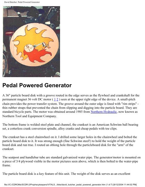
<strong>David</strong> <strong>Butcher</strong>: <strong>Pedal</strong> <strong>Powered</strong> <strong>Generator</strong><strong>Pedal</strong> <strong>Powered</strong> <strong>Generator</strong>A 36" particle board disk with a groove routed in the edge serves as the flywheel and crankshaft for thepermanent magnet 36 volt DC motor ( 1 2 ) seen at the upper right edge of the device. A small-pitchchain provides the power transfer system. The groove around the outer edge is lined with "rim strips" -thin rubber straps that prevented the chain from slipping and digging into the particle board. They arestandard bicycle parts. The motor was obtained around 1985 from Northern Hydraulic, now known asNorthern Tool and Equipment Company.The bottom frame is welded steel plate and channel, the crankset is an American Schwinn ball bearingset, a cotterless crank conversion spindle, alloy cranks and cheap pedals with toe clips.The crankset has a steel chainwheel on it. I drilled some larger holes in the chainwheel and bolted theparticle board disk to it. It was strong enough (fine Schwinn steel!) to hold the weight of the particleboard disk and run true. I routed an oblong hole through the particleboard disk for the "arm" of thecrankset.The seatpost and handlebar tube are standard galvanized water pipe. The generator/motor is mounted ona piece of 3/4 plywood visible in the motor pictures seen above, which is then bolted to the water-pipeframe.The particle board disk is a key feature of this unit. The weight of the disk serves as an excellentfile:///C:/CDROMs/SCDR-2/Prophecykeepers/VITALS.../bike/david_butcher_pedal_powered_generator.htm (1 of 7) [9/12/2004 11:44:02 PM]
<strong>David</strong> <strong>Butcher</strong>: <strong>Pedal</strong> <strong>Powered</strong> <strong>Generator</strong>flywheel. Human legs and pedals create an extremely "peaky" torque curve, resulting in jerky motion andlots of stress on parts. The flywheel smoothes this all out by absorbing part of the energy on the powerstroke, lowering peak torque, and releasing it on the "dead" part of the stroke, creating torque wherehuman legs/pedals cannot generate any. Another thing to remember is that human legs do not likeextreme stress. The flywheel allows the human to avoid having to generate extreme pressure during thepower stroke just to make it past the "dead" spots. Many "bicycle converters" lack the flywheelcharacteristic because tires/rims are designed to be so light.Noisy but extremely efficient, I have powered 12V CHAIN SAWS directly (yes, while someone else cutwood with them) with this unit.(1) <strong>Pedal</strong>ing position was similar to a bicycle. The seat is barely visible atthe upper left of the photo, and the handlebars (dropped, as on a ten speed road bike) are at the upperright.Burst output: 25 amps at 17 volts (425 Watts)30 minute average output (back when I was in shape) 150 WattsAccessories:A drill chuck threaded into the end of the motor shaft provided power for a flexible shaft drive. Drilling1/2" holes through 2x4 fir with this arrangement was easy. The flex-shaft was rated at 1/2 HP (acommercial unit, about 3/4 in. thick - not a "dremel" type!!) and I was still worried that the torque wouldbe too much for it.For immediate electrical use, cigarette lighter outlets provided ready access to the juice. I even had asmall 12v toaster oven, and pedaled my bagels to toast more than once. For storage I would charge a 12v100Ah fork-lift battery. I could approximate the output of a 10 amp battery charger.Be careful - I burned out several expensive 12v halogen bulbs powering them directly. I had no voltagecontrol and exuberant pedaling would fry the bulbs in short order. When the storage battery wasconnected, this was less of a problem because the bettery tended to even out the voltage, but sprintingwould still raise the voltage to the danger level.At one point a ball-bearing 3600 GPH pump was substituted for the generator, resulting in amazing waterpumping capacity. The suction from the pump was strong enough to collapse the heavy wall 1 inch vinyltubing used for the intake (radiator hose would have been better, with the wire reinforcement) and theoutput shot a stream of water about 25 feet across the street. A 5 gallon bucket was emptied using thispump in less than half the time it took a garden hose to fill it. I believe the pump was driven to capacity(1 gallon per seconds, emptying the bucket in five seconds) in sprints.Instrumentation consisted of a voltmeter and an ammeter, which together provided me with state ofbattery charge, output watts and somewhat of a "speedometer." The math was easy: VOLTS x AMPS =file:///C:/CDROMs/SCDR-2/Prophecykeepers/VITALS.../bike/david_butcher_pedal_powered_generator.htm (2 of 7) [9/12/2004 11:44:02 PM]
<strong>David</strong> <strong>Butcher</strong>: <strong>Pedal</strong> <strong>Powered</strong> <strong>Generator</strong>WATTS. A 50 amp silicon stud diode mounted to a four inch square piece of aluminum sheet metalprevented reverse current flows, and became satisfyingly warm after long sprints (it is mounted in thecenter of the aluminum plate visible in the first motor picture). For top efficiency (and safety), a switchwas also installed to completely isolate the diode and motor/generator from the battery.I never had a chance to determine how efficient the unit was in converting mechanical energy toelectrical energy, but I believe it was probably quite good. When running, only 4 ball bearings wereturning, the only high-speed part was the armature of the motor, and I know from research that chainscan be as high as 97% efficient in power transfer. The permag motor was probably better then average atpower generation, because it was designed to be efficient as a motor. In "reverse" tests, with the motordriving the unit with no load, the power consumed was less than an amp at 12 volts. This is negligible,and much of it was resistance loss in the motor windings, since the motor drew half an amp with no loadconnected to it.Status: The device outlasted me. I still have the motor and flex-shaft, but several job-related movesfinally forced me to dismantle the unit.Future: There are many other possibilities that I can think of for this device. The efficiency and variablespeed of the output are two features that can be exploited. Here are some other devices that could bepowered by the basic unit:●<strong>Pedal</strong> powered backup generator for solar electric systems. With the newly available white LEDas a light source, a few minutes of pedaling would be enough to create hours of light.●<strong>Pedal</strong> powered washing machine (this would be a tremendous workout, especially with thespin/sprint at the end!)●<strong>Pedal</strong> powered clothes dryer (when combined with a simple solar hot-air collector, the pedalswould tumble the clothes and move the air)●<strong>Pedal</strong> powered whole-house ventilation fan (15 minutes in the evening to cool off an entire house)●<strong>Pedal</strong> powered watering system when combined with a cistern to store rainwater●<strong>Pedal</strong> powered whole-house (central) vacuum cleaner - requires two people, of course●<strong>Pedal</strong> powered air compressor (compressing air takes a LOT of power, and is not very efficient.This would work for small jobs only, like staple guns, caulking guns, small hand tools - nojackhammers!!)●<strong>Pedal</strong> powered offset printing press, sewing machine (an ancient idea), hand tools (grinder, buffer,drill, reciprocating saw, lathe), mulch grinderfile:///C:/CDROMs/SCDR-2/Prophecykeepers/VITALS.../bike/david_butcher_pedal_powered_generator.htm (3 of 7) [9/12/2004 11:44:02 PM]
<strong>David</strong> <strong>Butcher</strong>: <strong>Pedal</strong> <strong>Powered</strong> <strong>Generator</strong>Basically, any device that was hand cranked, foot-powered, or powered by a fractional horsepowerelectric motor could potentially be converted to pedal power.Also note, if the base unit is being used to power an auxiliary device instead of producing electricity,adding a solar panel will result in additional power from the motor! That means whatever device you arepowering would receive the combined power of the human pedaler and the solar panel. Thiscombination makes the best of both power sources, as efficiency would be very high, because the solaroutput would not suffer the losses of being stored and then extracted from a battery. Charging a batteryand then extracting the same power is less than 80% efficient, and can be much worse. Direct utilizationcaptures that wasted power.Finally, keep in mind that a tandem setup for the pedals, with the pedals out-of-phase, doubles the powerand smoothes out the power flow. Only one "flywheel" is needed, so this enhancement needs only asimple pedal/seat addition to the basic unit. With out-of-phase pedals, peak torque is not increased, soother parts of the system are not stressed. The torque curve for a complete revolution of the flywheelsimply smoothes out, while RPM's stay constant, resulting in twice the power.Over time, a number of questions have asked about the information on the page. Here are someFrequently Asked Questions and answers/opinions:Do you have plans available?No. I am working on drawings of this generator and a recumbent version, but they are not yetavailable.Would a car alternator work better for generating power?No. Most automotive alternators have one ball/one sleeve bearing, a built-in power-robbingcooling fan, and they require external power to excite them at low-to moderate RPM's. They havenever been designed with efficiency in mind, since they were attached to monstrous motorscapable of producing orders of magnitude more power than the alternator required. They actuallyproduce AC power, which subsequently must be rectified to DC to charge batteries. This stepcauses significant power loss in the diodes (around 5%). As I noted above, I ran power outputaround the diode and directly into the battery to avoid this loss. In addition, alternators aredesigned to run at extremely high RPM's (alternator pulleys are smaller than the driving pulley onthe engine, meaning the alternator turns FASTER than the car engine. Look at your tachometerreading and double it. Whew!), and do not produce usable power until they are rotating quiterapidly, requiring high ratio's of step-up from your pedals. A well-designed permanent-magnetball-bearing motor, preferable one designed to squeeze every last bit of power out of a set ofbatteries, will beat an automotive alternator in efficiency.file:///C:/CDROMs/SCDR-2/Prophecykeepers/VITALS.../bike/david_butcher_pedal_powered_generator.htm (4 of 7) [9/12/2004 11:44:02 PM]
<strong>David</strong> <strong>Butcher</strong>: <strong>Pedal</strong> <strong>Powered</strong> <strong>Generator</strong>Wouldn't gears help generate more power? And what about belts instead of chains?Maybe. Humans can only pedal through a small speed range, about 40-120 RPM's. Below thatyou can strain your joints, and above that efficiency falls off. There is a "magic" speed (differentfor every human being) at which they can generate maximum power. The proper gear ratioenables the human to pedal at that speed. You may have noticed, though, that a human'smaximum power output can change quickly from fatigue, and slowly from changes inconditioning and age. The magic speed is always changing, so having a few closely-spaced"gears" or ratios may enable a better match of human to generator. No matter what, though, gearsdon't create energy, they waste energy, so having fewer of them is always better. The samegoes for bearings, even ball bearings. The pedal-power generator described on this page had veryfew of both, so it was very efficient.Regarding belts, the transfer efficiency of most belts is less than chains. This is mostly due toflexing energy loss within the belt material and friction losses at the engagement points betweenthe belt and the pulleys. Belts also work best when transferring low torque at high speed (theopposite of what a pair of legs produce!) which is why you do not see them on bicycles, forexample. There may be some exotic, thin, high strength belts that could approach the efficiency ofchains with the right design. For example, the "serpentine" belts used in modern automobileengines are much more efficient than the old "V-belts" from the past. Belts rely on friction totransfer power. Friction is bad. The best feature of belts is that they are quiet, so I can't say toavoid them completely. If you decide to use a belt to transfer power, use the thinnest, strongestbelt you can find, and place only enough tension on it to keep it from slipping during use. I do notknow whether equivalent "toothed" and "grooved" belts are equally efficient, but I believe thetoothed belt has slightly lower friction losses. If I can ever find some real research data on the webI will link it in here.How much power can one human being create?This is an opinion. I used to be a competitive swimmer, and for a number of years, I worked out 6hours a day, swimming approximately 13 miles. Yes, 13 miles a day. If you pedaled that hard forthat long you might be able to run one ordinary refrigerator for 24 hours. To make any kind ofsignificant contribution to your energy supply, you must use the most efficient devices youpossibly can. For example, a small refrigerator designed to be powered by solar power would bemuch more practical. A rule of thumb: if the device was designed to be powered by batteries, evenBIG batteries, you might be able to keep up with it.If your electric bill shows KWH (kilowatt-hours), take the number, multiply by 4 (assuming youcan crank out 250 watts for an hour) and that is how many hours you will have to be in the saddleto create the same amout of power. Sorry, it can be depressing. The moral: Using less power is asimportant, if not more important, than making more.file:///C:/CDROMs/SCDR-2/Prophecykeepers/VITALS.../bike/david_butcher_pedal_powered_generator.htm (5 of 7) [9/12/2004 11:44:02 PM]
<strong>David</strong> <strong>Butcher</strong>: <strong>Pedal</strong> <strong>Powered</strong> <strong>Generator</strong>There are numerous sources of efficient appliances on the web. One place I like to shop is RealGoods, and of course I have spent time inventing my own efficient devices. The white LED light Ibuilt shows how technology can create new solutions to increase efficiency. <strong>Pedal</strong>ing for an hourat the 200 watt pace, with 80% efficiency of generation/storage/extraction, would create enoughenergy to run that light for 320 hours!!!Can I generate 110V? Can I run my electric meter backwards?I don't recommend this! If someone were to replace the permanent magnet DC motor in a pedalgenerator (such as the one on this page) with a 1/4 to 1/2 horsepower 110V induction motor andpedal that it would result in an amazing thing. If the motor was hooked to the power lines and itwas "pedaled faster than it wanted to go", it would start generating 110V alternating current.Beautiful sine wave AC. If it was creating more energy than your clocks, refrigerator, all thoselittle square black power supplies you have plugged in around the house, your lights, and that 300watt stereo you are listening to while you pedal all use together, your electric meter would slowlycreep backwards. However, that same motor would generate exactly 0 power if it is not pluggedin to 110V AC.For very light duty "off the grid" use of 110V AC, you can try pedaling your 12V DC generatorinto a large battery and hooking up an inverter (12V DC - 110V AC) to get some pretty decent110V power. You CAN'T use this method to "run your meter backwards"!!!! In general, plan onbeing able to pedal about 100-250 watts for half an hour or so.For efficiency, however, you are much better off producing 12V DC for a 12V DC TV (forexample) than you are producing 12V DC to charge a battery to run an inverter to power a110V AC TV. The UPS (uninterruptable power supply) for my website computer system canpower the computer for about five minutes. The same battery (12v 1.5 AH) would power mylaptop computer for about 45 minutes. Everything (efficiency-wise) works FOR you when thedevice being powered is designed to be efficient (12V DC) and AGAINST you when it is not(110V AC).How big should my batteries be?If you are considering building a similar system, plan on using two batteries, and a simple switchwhich allows you to use one while charging the other. Flip this switch right before you begincharging to ensure that you are charging the battery with the lowest charge (the one most recentlyused). Also be sure to use a battery that is roughly equal to ten or twenty times your power outputfor a charging session. For example, if you crank out ten amps for an hour each time you charge,choose a 100-200 amp hour battery. Larger batteries will simply loose charge through selfdischargefaster, resulting is less efficiency for your system and more useless work for you.Remember:file:///C:/CDROMs/SCDR-2/Prophecykeepers/VITALS.../bike/david_butcher_pedal_powered_generator.htm (6 of 7) [9/12/2004 11:44:02 PM]
<strong>David</strong> <strong>Butcher</strong>: <strong>Pedal</strong> <strong>Powered</strong> <strong>Generator</strong>1. The most efficient way to use the power you create is not to create electricity at all, but topower your (pump, fan, hoist, winch, drill press, grinder, sewing machine, etc.) directly.2. The second most efficient way to use the power is to pedal a generator to electricallypower your (television, radio, floodlight, chain saw, laptop computer) directly, with nobattery. Be careful about voltage, or use a good regulator.3. The least efficient way to use your power is to generate electricity and store it in a battery,then extract it from the battery to power some device. Avoid this method in favor ofmethods 1 and 2!!For more information, read this excellent writeup giving details on a different design based on a bicycleand rollers. .(1) Three things about the chain saw. One, I was in great shape and probably was generating over onehorsepower in the sprint. Two, the branch/log was about three inches in diameter - not anything near the14 inch bar length. And three, the saw was a 12 volt saw, so it was designed to be efficient. The literaturefrom the saw said that the motor was a permanent magnet Bosch electric winch motor, which was a goodmatch for the maximum output of the pedal generator. It was great to see the chips fly!Back To: [ <strong>David</strong> <strong>Butcher</strong>'s Personal Page ]This page is hosted by The WEBworks * Copyright 1994, All Rights Reservedfile:///C:/CDROMs/SCDR-2/Prophecykeepers/VITALS.../bike/david_butcher_pedal_powered_generator.htm (7 of 7) [9/12/2004 11:44:02 PM]
<strong>David</strong> <strong>Butcher</strong>'s Micro Solar Energy System<strong>David</strong> <strong>Butcher</strong>'s Micro Solar Energy SystemI have always been a solar energy nut. I finally have a small photovoltaic system up and running,generating 12 volt power (though in very small amounts) and providing me with a way to learn what Ineed to know before I expand to a large scale "off the grid" system.I began the small solar lighting system to light one dark hallway and my garage. Of course, things haveprogressed from there. Solar electric systems are easily expanded, and I started with a very small system.I had plans to expand it over time. Here is the chronology:The project actually began in the 1970's when I begin building solar cell panels and teaching workshopson panel construction. Among the many small solar panels I built was a 12 volt, 1 amp panel built withsingle crystal 3 inch silicon cells. The panel had never really been put into service, but through all mytravels I kept it with me, and I finally decided to celebrate the new millennium by permanently installingit and finding something useful to do with the power it generated.The first installation consisted of a Trace C12 charge controller, two very small (4 AH at 6 volt) gell cellbatteries and a white LED light of my own design.The light has 6 white LED's, arranged in two circuits, with a fan switch which gives bank A, bank B andboth banks with successive pulls of the cord. The light tube is free to rotate, giving the light the ability tobe directed through a 180 degree arc. Power is 12v DC, and each bank of 3 LED's draws 20ma - yes,twenty milli-amps. The entire light, including switches, materials, LED's, screws to hook it to the roofand even the wire inside the light cost under $25 !!The light is a prototype. I will construct a brighter version when the next set of LED's arrives. Here is acloseup of one end of the light to show the two-way pull switch.It's not a twin tube 40 watt fluorescent shop light by any stretch, but it is impressive how much light canbe produced by running only half a watt through these little solid state lamps.I will create detailed plans if anyone is interested.Mon Sep 04 17:31:21 PDT 2000Well, the "micro" name may have to be dropped. I have added three more solar panels to the system.Here are the details:1. I bought a small (250ma, 12v) panel on sale at Real Goods for $39 (regularly $69) and wired it in.It is weatherproof, has it's own blocking diode, and it is now mounted fairly high up on the eaves.2. I took my oldest 12v panel, 30 200ma "satellite" cells assembled into a panel in 1982, andhttp://www.los-gatos.ca.us/davidbu/micro_solar/index.html (1 of 5) [9/12/2004 11:44:17 PM]
<strong>David</strong> <strong>Butcher</strong>'s Micro Solar Energy Systemmounted it in a clear skylight. This panel only produces about 15v instead of the usual 18v (36cells is typical), so it is more valuable when there is a load on the system or when the batteries arefairly low.3. About five years ago I bought 4 used solar panels for $75 each. In July I built a redwood frame(aluminum is sometimes referred to as "solid electricity" because of the amount of power (i.e.coal/oil/nuclear) required to produce it. Redwood is renewable.) to hold the panels. Everythingwent well, and I now have a 4 foot square panel. That is large enough to produce around 100watts! The panel lives on the roof of the garage, and I use the power it generates to rechargeeverything inside the house on "Sunday" every week.Now the system is starting to really produce some power! In fact, I found that the combination of smallpanels kept the batteries charged all week, running the LED lights I had in the hallway and in the kitchen,and I had enough power with the big panel to run a solar powered drip coffee maker on the weekend!Even after making coffee, there was power to spare.I am now cleaning up the system and considering adding more lights in several places in the house. With28AH of batteries and the panels I have, I can probably have two or three times as many LED lights as Ihave now. I will be building more lights soon, and I will also create a diagram of the system to show howall the pieces fit together.Sat Sep 16 23:06:50 PDT 2000Today I made some progress on system reliability. I followed instructions from Home Power magazine,and built a battery desulfator circuit. This circuit pulses the batteries with high current, high frequencycurrent which results in elimination of sulfate buildup. The circuit is small, and it looked easy to build. Ihave it working on an old 25AH Gell Cell battery that I bought new, never used, and is now severelysulfated. Something is definitely happening, as the charge current on the battery is gradually increasingfrom almost nothing (3 ma). I'll post the results here, but it may take several weeks to determine whetherthe battery can be saved.Sat Nov 25 09:43:12 PST 2000Big changes are taking place. The solar system has become a tangled mess of wires, inverters, alligatorclips and cords. Today I will work on organization. I will present photographs later today showing howthe different components fit together. To make a presentation, I have been attaching the components toone foot square ceramic tiles. While this will take up more space on the wall, it will also enable thesystem to be cleanly organized and modular.Sun Feb 17 19:42:39 PST 2002Wow. The time flies. I have had white LED's in our walk-in closet for almost a year. They are poweredby three Ray-O-Vac D Alkaline rechargeable batteries, charged weekly using a small (140 watt) 12v tohttp://www.los-gatos.ca.us/davidbu/micro_solar/index.html (2 of 5) [9/12/2004 11:44:17 PM]
<strong>David</strong> <strong>Butcher</strong>'s Micro Solar Energy System120v inverter, and an Ray-O-Vac battery charger. The system has worked like a dream. I have a smallmicroswitch (Radio Shack) on the door, and the LED's turn on automatically when the door is opened.90% of the time my wife and I use this light source instead of turning on the two 40 watt florescentlighting fixtures. Fabulous!Elsewhere in the house, I have created more LED "strip lights." Under the kitchen cabinets, I have threesets of three white LED's where I used to have 110v strip lights. These LED lights are wired (though thekitchen wall) to the 12 volt power source in the garage. A simple pull-switch turns them off and on. Withthese lights available, the 150 watt track lights in the kitchen are seldom turned on. Another big win forsolar energy!I have also created a 6 LED light fixture for the short hallway between our house and the garage. Thissimple fixture has two features. It is turned on by a microswitch, just like the closet lights, and it hasseveral large capacitors (about .1 farad) in the circuit with the LED's, so the light does not turn offimmediately! This allows me to walk out into the garage and then back after the door closes. The doorcloses automatically to comply with fire codes.These projects have enabled us to "kill" a number of 120v grid powered lights. While the 120v lights arestill available, the 12v solar LED lights are automatic, and they are almost always enough. Simple, easy,cheap, and hundreds of times less power-hungry than their 120v counterparts.Mon Oct 28 18:39:58 PST 2002Big changes! Since the last entry, my wife and I bought a house. In the process of moving, every solarsystem had to be taken apart. Little by little, I have been putting them back together. One of the systems Icannot live without is the under-counter lights in the kitchen. This time, as I built the system, I took somepictures of the process. I believe anyone could do what I did, and create similar lights. These lights arepowered by rechargeable batteries, and the batteries are charged with solar electricity, so they are "offgrid."Here are the details.Thu Nov 7 15:45:57 PST 2002A strange thing happened today. It is raining, so I figured it would be a good day to clean up some of thewires on the Microsine Inverters (OK4 for you NKF fans). When I did my ususal "finger test" to see ifthey were warm (active), one was stone cold. Now I admit it was raining, and I did not expect muchpower to be generated, but the other one was noticeable warmer. I went inside and got my laptopcomputer, hooked it to the OK485 computer interface, and checked up on the inverters. Sure enough, onewas putting out 15 watts and the other was at zero. Interestingly, the one at zero said that it could notread the "plug" voltage: 120 volts AC. After much fiddling, and switching wires around, and "rebooting"the inverter by unhooking it from both the 120 volt AC line and the 24 volt DC solar panel, I was readyto give up. Then I rememberd one of the old tricks I had learned back when I repaired computers for aliving. I took a screwdriver, held onto the metal end, and whacked the inverter with the handle. Ithttp://www.los-gatos.ca.us/davidbu/micro_solar/index.html (3 of 5) [9/12/2004 11:44:17 PM]
<strong>David</strong> <strong>Butcher</strong>'s Micro Solar Energy Systemimmediately fired up and began producing power. Sometimes the low-tech solution is the best solution. Ihave mailed NKF tech support for suggestions. It could be a cold solder joint, or some other problem.Whaterver is was, it is "fixed" for now.<strong>David</strong> "Photons, not Neutrons" <strong>Butcher</strong>DisclaimerThis information is provided in good faith but no warranty can be made for its accuracy. Follow thesesuggestions at your own risk! If you notice something incorrect or have any comments, or information toadd to these pages, feel free to mail me.First and Last Name:Email (Optional):Please enter any questions or suggestions you have in the area below:To send your comments to <strong>David</strong> <strong>Butcher</strong>, press this button: .<strong>David</strong> <strong>Butcher</strong>davidbu"at"www.los-gatos.ca.usTel (408) 978-5495Los Gatos, California 95030http://www.los-gatos.ca.us/davidbu/micro_solar/index.html (4 of 5) [9/12/2004 11:44:17 PM]
Bicycle <strong>Powered</strong> <strong>Generator</strong>Bicycle <strong>Powered</strong> <strong>Generator</strong>I skim a few Usenet newsgroupsdaily, among themmisc.survivalism andalt.energy.homepower. Frequentlyposters on these two groups willinquire about generatingelectricity using a stationary bikecoupled to some sort of generator.Most replies are to the effect thatwhile it's possible to do this, theamount of power output by such arig when pedaled by the averageperson wouldn't be worth theeffort. I wasn't convinced that thisidea was a lost cause. I decided tobuild one and see how well itworked.Because bikes are made in a range of sizes to match their rider's stature I wanted to build the generator asan accessory which could be driven by any ordinary bicycle. I used to work in a bicycle shop when I was13 and remember seeing the owner, Mr. Hank, ride his track bike on a set of rollers. While I was lookingthrough bike accessory catalogs for rollers that I could adapt to my purposes I came across anothersimilar device called a training stand. While rollers require a lot of skill to ride because there is nothingbut the gyroscopic force of the spinning wheels and the rider's balance to hold you upright, a trainingstand clamps on the rear axle of the bike and keeps you vertical.http://users.erols.com/mshaver/bikegen.htm (1 of 6) [9/12/2004 11:44:23 PM]
Bicycle <strong>Powered</strong> <strong>Generator</strong>To make a long story shortI bought the most versatiletraining stand I could findand then did extensivemodifications to the rollerassembly. Originally theball bearings were pressedinto the bore of the roller atthe outer ends. The rollerassembly spun on astationary axle fixed to theframe. The end of theroller, opposite the integralthree pound flywheel,drove the hub of acentrifugal clutch. Theshoes of the clutchengaged a stationary drumwhich provided resistanceincreasing with speed. I had to make a new axle which is locked to the roller and move the bearings tomachined aluminum plates outboard of the steel frame. The plates are made to a standard NEMA 42 sizeand provide the mounting surface for a permanent magnet DC motor that is driven as a generator througha flexible coupling. The other end of the axle exits from the bearing through an identical plate and isavailable for PTO use. You can see a black sprocket on that end of the axle in the pictures. I also had toweld in a brace to stiffen up the frame to allow carrying the extra weight of the generator. I'm pleasedwith the result. Even under heavy load it runs cool and relatively friction free. The part of the frame thatclamps to the rear axle of the bike pivots with respect to the ground so that the rider's entire weight forcesthe tire into contact with the roller reducing slippage to a minimum. The black object under the frontwheel is a contoured plastic block that levels the bike to avoid the feeling of riding downhill.http://users.erols.com/mshaver/bikegen.htm (2 of 6) [9/12/2004 11:44:23 PM]
Bicycle <strong>Powered</strong> <strong>Generator</strong>I have done quite a few tests to see how muchoutput power could be produced and whatpractical applications there were. See thetables below for a list of those tests and theresults. In summary I think the most practicalapplication of the bicycle powered generatorwould be battery charging. This applicationpresents a constant load to the rider whichallows them to select a single gear ratiowhich lets them pedal at their optimalcadence. Another practical application isrunning small appliances and tools which useuniversal series wound motors or permanentmagnet DC motors. All of the motorizeditems in the table below have universal serieswound motors and would run on DC eventhough their nameplates all said "120 VoltsAC Only". Induction type motors such asthose found in washing machines and shadedpole motors which are used in clocks reallyare AC only and won't work at all. I couldn'tget my variable speed drill to work, probablybecause the speed control electronics are incompatible with DC. Good candidates are appliances or toolsthat can perform their functions with 300 watts of input power or less and which present a narrow rangeof loads such as the mixer and electric drill. Although producing heat with electricity is usually a badidea, I think that small soldering irons might also work well since they are almost all are under 100 wattsand most are less than 50 watts. Since there is no voltage regulation at all, connecting the generatoroutput directly to the power input jack of battery powered TVs, radios, and similar devices will probablydestroy the sensitive electronics. Use the generator to charge the batteries, and power the electronicsfrom the batteries. Since the generator is capable of outputting several amps it may be best to charge onlybatteries that can accept a charging rate in this range, and then building an efficient switchmode regulatorto charge smaller cells and batteries off of the large battery. The final, and as yet unexplored, applicationis hitching mechanical loads such as a water pump or grain grinder to the PTO end of the axle usingroller chain. I expect a lot more useful work out of this arrangement as it avoids the inefficientconversion of the rider's mechanical energy into electricity and then back to mechanical energy viaelectric motors. Using 27" tire diameter on the bike and a 10 MPH "road speed" the roller will turn atabout 2600 RPM. The sprocket shown is the smallest I could find at 9 teeth for 1/2" pitch #41 chain, soyou would need to figure from there what size sprocket you need on the load to give the desired loadRPM. One suggestion that came up during testing was to drive a heavy flywheel to dampen out electricalload variations, but that was never tried.Electrical Tests:http://users.erols.com/mshaver/bikegen.htm (3 of 6) [9/12/2004 11:44:23 PM]
Bicycle <strong>Powered</strong> <strong>Generator</strong>Load Output CommentsOpen CircuitShort Circuit2 Ohm Wirewound Resistor65 Ohm Wirewound Resistor100 Ohm Wirewound Resistor230 Volts DC4 to 5 Amps DC5.5 to 6 Volts DC (15 to 18Watts)100 Volts DC (150 Watts)Continuous, 130 Volts DC (260Watts) Peak100 Volts DC (100 Watts)Continuous, 150 Volts DC (225Watts) PeakPractical tests:Spinning it as fast as possible in thehighest gear that the test bike hadand measuring the output with aDMM.<strong>Generator</strong> output shorted by theDMM on the 20A DC scale. Thismeasurement doesn't mean muchbecause it took a lot of torque to turnthe generator against a short circuit.It was hard to get consistent readingsdue to the speed fluctuations fromthe low rate of pedaling that couldbe achieved.This test had the same problem asthe short circuit current test, the loadimpedance was too low to allow therider to pedal effectively.The continuous figure is what therider felt he could keep up for 15 to30 minutes. The peak value was afew second burst of speed.The difference between this test andthe previous one could be variabilityof effort on the part of the rider,perhaps as a result of fatigue.Another possibility is impedancemismatch between the source(generator) and load. The generatorhas a very low output impedanceand the ideal load would be thelowest resistance that will still allowthe rider to pedal at an effective rate.Load (Nameplate Data)Results Commentshttp://users.erols.com/mshaver/bikegen.htm (4 of 6) [9/12/2004 11:44:23 PM]
Bicycle <strong>Powered</strong> <strong>Generator</strong>Battery ChargingWaring Multispeed HandmixerBlack & Decker 3/8" Drill Model 7104Type 1 (2.9 Amps 1200 RPM)Black & Decker 7-1/4" Circular SawModel 7308 Type 5(1-1/2 HP 9 Amps1200 RPM)GreatGoodFairPoorAble to push a continuous 4 to 6 amps into a 12Volt automobile battery. The best setup was toput a rectifier diode in series with the generatoroutput. This stopped the battery current fromdriving the generator backwards and enabled therider to start pedaling without any initialresistance. It was then possible to take up thecharging current load gradually as the generatoroutput exceeded the battery voltage plus theforward voltage drop across the diode.Moderate pedaling effort was required to run thisappliance up to operating speed. I loaded themotor by trying to slow the rotation of the beatersby hand. There was plenty of available torque touse the mixer in its typical applications. I'mcertain that similar appliances such as blendersand food processors would work just as well.Lots of 1/4" holes were drilled through a 2" thickpiece of framing lumber with a standard highspeed twist drill and I'm sure that larger holeswould be possible. The only special considerationwas to ensure a steady feed rate while drilling toavoid load fluctuations.Considerable pedaling effort was required to getthe saw up to operating speed and it bogged downto a standstill when a cut through a 2 x 4 wastried. We might have been able to cut 1/4"plywood or luan. I think the problem is that themotor in this tool is designed for maximum poweroutput regardless of conversion efficiency. I'msure a person has enough power to saw a board,after all, I can do it with a hand saw using onlythe muscles in one arm! I would like to try thistest with a saw designed to run efficiently on DCsuch as the battery operated ones made byDeWalt.http://users.erols.com/mshaver/bikegen.htm (5 of 6) [9/12/2004 11:44:23 PM]
Bicycle <strong>Powered</strong> <strong>Generator</strong>McCulloch ElectraMac Chainsaw ModelEM14ES (2 HP 11Amps)UselessThis tool's motor has the same characteristics asthe circular saw. It was impossible to get it up tofull speed, and the blade merely bounced off thesurface of the log and stalled when anymeaningful cutting force was applied. Thenameplate claimed 2 horsepower and the motor'ssize was perhaps 3" in diameter and 6" long.Acknowledgements:During my "what if" phase of research on the internet I was directed to <strong>David</strong> <strong>Butcher</strong>'s <strong>Pedal</strong> <strong>Generator</strong>page which provided me with the proof of concept I needed to justify building my own version of abicycle powered generator. I think my results correlate well with his.I would also like to thank my long time friend Mike who spent several hours with his Paramountmountain bike clamped in my contraption pedaling diligently while I measured and fiddled around. Forreference he is in his mid 50's, in good physical health, a non-smoker and semi-regular recreationalcyclist, so you can scale your own expectations accordingly.http://users.erols.com/mshaver/bikegen.htm (6 of 6) [9/12/2004 11:44:23 PM]
http://www.got.net/~davidbu/davidbu/micro_solar/bar_light.jpghttp://www.got.net/~davidbu/davidbu/micro_solar/bar_light.jpg [9/12/2004 11:44:45 PM]
http://www.got.net/~davidbu/davidbu/micro_solar/light_end.jpghttp://www.got.net/~davidbu/davidbu/micro_solar/light_end.jpg [9/12/2004 11:44:46 PM]
http://www.got.net/~davidbu/davidbu/micro_solar/desulfator.jpghttp://www.got.net/~davidbu/davidbu/micro_solar/desulfator.jpg [9/12/2004 11:44:46 PM]
<strong>David</strong> <strong>Butcher</strong>'s Micro Solar Energy System: Under Cabinet LED LightMicro Solar Energy System: Under Cabinet LEDLightAs in many kitchens, we have lights under the cabinets to light the kitchen counters. These lights arepowered by 110v (the grid) and are fluorescent. They are relatively efficient, but they are all wired to thesame switch, and they all come on at once. They are too bright for the gentle "ambient light" my wife andI like to have in mornings and evenings, when we are just making coffee or drifting in and out of thekitchen to visit the sink or refrigerator. We wanted a light that was solar powered, efficient, based onwhite LED technology, and much less bright. With a little effort, we built one! This page is for the do-ityourselfsolar light enthusiast. Anyone could build one of these lights! While it does not have to be solarpowered, simply recharging the batteries from a solar panel is all it takes to keep the lights "off the grid."This project is an excellent starter project for a small solar system, and it would make an excellent schoolscience fair project as well! Here are the details:The light has 3 white LEDs, with a pull switch used to turn it on an off. The light body is free to rotate,giving the light the ability to be directed through a 180 degree arc. Power is 4.5v DC, and the 3 LED'sdraw 20ma - yes, twenty milli-amps. The entire light, including switches, materials, LED's, and even thewire connecting the batteries to the light the light cost under $25 !!It's not as bright as the 40 watt fluorescent lights next to it by any stretch, but it is impressive how muchlight can be produced by running only one tenth of a watt through these little solid state lamps.The LED lamps are powered by three Ray-O-Vac D Alkaline rechargeable batteries, charged weeklyusing a small (140 watt) 12v to 120v inverter powered by a solar panel and battery, and a Ray-O-Vacbattery charger. The system has worked flawlessly. 90% of the time my wife and I use this light sourceinstead of turning on the five 20 watt florescent lighting fixtures. In other words, we are using 1000times less energy to produce the light we need for many of the activities in the kitchen.This single project enabled us to dramatically reduce the use of a number of 120v grid powered lights.While the 120v lights are still available, the solar LED lights are convenient, and they are almost alwaysenough. They are simple, easy to build, cheap, and hundreds of times less power-hungry than their 120vcounterparts.Are you ready to build your light? Let's begin!●Materials required:❍ Wooden dowel 36in./1 meter long, and 1/2in./1.25cm in diameter(1)❍ "D" Cell battery holders (sufficient for 3 cells)❍ White LED's (3 or more)❍ Pull chain switch (1)http://www.los-gatos.ca.us/davidbu/micro_solar/bar_light.html (1 of 5) [9/12/2004 11:44:50 PM]
<strong>David</strong> <strong>Butcher</strong>'s Micro Solar Energy System: Under Cabinet LED Light●●❍ Terminal block (1)❍ Small gauge wire, 2 conductor "zip cord" is ideal (6 feet/2 meters)❍ Fuse holder and 250ma fuse (1 each)❍ 50 Ohm 1/2 watt resistor (other values may be required, will be explained later)❍ Large cup hooks (2)❍ Electrical tape (36 in/90 cm)❍ Block of wood to hold parts (6in x 6in x 1/2 in, 15cm x 15 cm x 1cm)Tools required:❍ Small screwdriver❍ Drill - 3/8 inch bit❍ Soldering iron (25-30 watt)❍ Wire cutters, or "Xacto Knife" - any small sharp knife (gloves recommended)❍ Small wood or metal saw, if dowel needs to be trimmed for lengthTime required to assemble and install: 2-3 hours1. Understanding the design, and theory of operationThe design of the light is extremely simple. The light itself is constructed of a wooden dowel. TheLED's are attached to the dowel, using electrical tape. One is attached in the middle, and the othertwo are attached at each end. The wire runs the length of the dowel. The dowel is then placedunderneath the cabinet and suspended from the two cup hooks. That cup hooks should be fairlyloose, allowing the dowel to be rotated. This will allow the light to be aimed in the most effectivedirection.The light is powered by three rechargeable D cell batteries. The LED's require 4.5 volts tooperate. The three D cell batteries provide this when they are connected in series. The maximumcurrent the LED's can tolerate on a long term basis is 20 ma. Three freshly charged D cells willdrive more than that much current through the LED's, shortening the life of the LED's. To controlthis current, a resistor is inserted between the batteries and the light. For safety, a small fuse isalso installed.2. Choosing a location for the lightThe best place to install the light is in the work area that does not require bright light, but isfrequently used. I usually set my light up close to appiliances I use early in the morning, such asthe coffee maker. These lights are not really bright enough for complicated cooking tasks, butthey might be enough for loading a dishwasher, and they are certainly bright enough to help youfind the 'fridge!3. Assembling the lightAfter you have determined where the light will be, measure the length of the space and cut thehttp://www.los-gatos.ca.us/davidbu/micro_solar/bar_light.html (2 of 5) [9/12/2004 11:44:50 PM]
<strong>David</strong> <strong>Butcher</strong>'s Micro Solar Energy System: Under Cabinet LED Lightdowel to fit, if necessary.Now begin to wire the light by taping the wire down the length of the dowel. Flatten it out (notwists) so the conductoes do not "switch sides" as the wire travels down the dowel. Tape the wireto the dowel in three places: the middle, and both ends. Wrap the tape around the dowel an inch orsoA from the ends of the dowel. The wire should end at the end of the dowel on one end, and theremaining wire should continue for several feet past the other end of the dowel.Next prepare the wire for soldering on the LED's. Examine the wire closely. If it is "zip cord", itwill have two conductors joined together by the insulation surrounding them. One of the twoconductors will be identified in some manner. The wire will be a different color, or have a coloredstripe on the insulation. This will be the "positive" wire. Each LED will be attached between thepositive and negative wire. In the next step, you will cut through the insulation exposing the barewire at each point that an LED will be attached, enabling the LED's to be soldered to the wire.Beginning at the end of the dowel with the long piece of wire extending from it, cut into thecenter of the wire about one inch (closer to the middle of the dowel) from the electrical tape.Carefully pull the two individual wires apart intil they are far enough apart to stick your fingercomfortably between them. Do this step at each location you are planning on having an LED. Atthe other end of the dowel, simply separate the two wire for about 1/2 in. (1 cm.).Take a moment to check your work before the next step. You should have a dowel that is the rightlength to fit easily in the space you have chosen. It should have a wire taped to it, with one end ofthe wire stopping right at the end of the dowel, and the other end extending past the end of thedowel by at least 1 foot (30 cm). The wire should be laying flat on the dowel, with no twists. Atevery place along the length of the wire where you are planning on attaching an LED, you shouldhave cut through the insulation and separated the conductors a bit. There should be no bare wiresat this point. Ready for the next step?The conductors in the wire must be exposed so the LED's can be soldered onto them. Theinsulation must be cut away from the wire to allow this. There are two possible ways toaccomplish this:1. Cut the wire completely at each LED position, and strip the insulation off the cut ends.2. Carefully "carve" the insulation away from one side of the wire, leaving the conductorsintact. If you have patience, carve all the insulation away from 1/4 in (1 cm.) of the wire -both conductors.If you choose option 1, your soldering job will be cleaner, but you may need three hands to holdeverything while soldering. You will need to hold both ends of the wire, the LED, the solderingiron, and possibly the solder! If you have a helper, this is probably the better technique.http://www.los-gatos.ca.us/davidbu/micro_solar/bar_light.html (3 of 5) [9/12/2004 11:44:50 PM]
<strong>David</strong> <strong>Butcher</strong>'s Micro Solar Energy System: Under Cabinet LED LightIf you choose option 2, the wire itself will not be cut, so you will be able to hold the LED onto itwith one hand and hold the soldering iron with the other hand. You can probably assemble thelight without a helper if you choose option 2. One possible problem with this technique is that anyremaining insulation on the back side of the wire (if you could not cut it completely away) willprobably melt during the soldering, so the finished work may look a little messy.At the end of the dowel where the wire stops, simply trim the insulation back 1/4 in. (1/2 cm.) sothe bare wire is exposed.It is time to prepares the LED's for soldering. Handle the LED's with care. If you happen todevelop a sharge of static electricity, and touch a LED, it could be "zapped!" That means nopetting the cat during this next activity!LED's have two wires (also called "leads") coming out of the bottom, and lens on the top thatfocuses the light. Look closely at the leads - one is longer than the other! Not by much, but theredefinitely is a difference. The longer lead will be attached to the positive wire on the light, and theshorter lead will be attached to the negative wire.Before soldering the LED's onto the wires, bend the leads on each LED to make the job easier.Bend the leads about 1/4 inch (.5 cm.) from the bottom of the led. bend them in oppositedirections, intil they are at 90 degrees from their original position. You should be able to gentlyset the LED on to the wires you stripped, with each lead going to its respective wire. It won't saythere, of course - that is what the solder is for. Don't bend the leads on all your LED's yet, or youwill loose track of which lead is positive! Bend them one at a time, right before you are ready tosolder them, and keep track of which lead is which.4. Assembling the power source5. Testing6. Installing the switch7. Installing the light and power source8. Testing and troubleshooting9. Maintenance<strong>David</strong> "Photons, not Neutrons" <strong>Butcher</strong>DisclaimerThis information is provided in good faith but no warranty can be made for its accuracy. Follow thesesuggestions at your own risk! If you notice something incorrect or have any comments, or information tohttp://www.los-gatos.ca.us/davidbu/micro_solar/bar_light.html (4 of 5) [9/12/2004 11:44:50 PM]