Infrared readout electronics for space science sensors - Eric Fossum
Infrared readout electronics for space science sensors - Eric Fossum
Infrared readout electronics for space science sensors - Eric Fossum

Create successful ePaper yourself
Turn your PDF publications into a flip-book with our unique Google optimized e-Paper software.
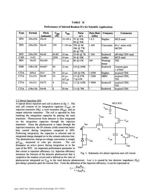
Type Format Pitch(jtmxjtm)TABLE IIPer<strong>for</strong>mance of Selected Readout ICs <strong>for</strong> Scientific ApplicationsC1(if)T.tNoise(e)SFD 256x256 30x30 ? 10-100 s 55 10K48 @ 50KSFD 256x256 30x30 270 > 150 ms 700 @ 4K186@77K60 @ 77KData Rate Company Comments(kHz)> 6.5 Hughes MCS used< 400 Cincinnati 60 e noise withMCDSSFD 256x256 40x40 60-85 10 ms 19-40 @ 7K < 300 Rockwell off-chip CDS usedCAD 1x32 ? 2200 10 sec 10 @ 20K ? Amber MCS usedBDI 30x92 50x100 ? 3 12 ts 80 @ 67K 300 WestinghouseTDIGMI 128x128 60x60? 40 22 ms 4.8 @ 200K ? Rockwell Current gain> 47000CTIA 260x1 25x? 30 42 ts 120 67K < 6500 Hughes in-pixel CDSCTIA 32x134 50x50 10 42 ts 1.9 @ 67K < 3200 SBRC in-pixel CDS;167s 7@67KmlCTIA 10x132 25x75 4 25 ts 3.3 145K < 5000 Rockwell in-pixel CDS;mlCTIA 128x128 50x50 4 20 ms 3.4 78K ? Rockwell in-pixel CDS3.2 Direct Injection (DI)A typical direct injection unit cell is shown in fig. 3. Theunit cell consists of an integration capacitor (Cint), aninjection transistor (M1), a reset transistor (Mrst) and anoutput selection transistor. The cell is operated by firstresetting the integration capacitor by pulsing the resettransistor. Photocurrent from detector is then integratedon the integration capacitor through the injectiontransistor. Since the photocurrent is input through theinjection transistor, the DI scheme yields somewhat betterbias control during integration compared to SFD.Following integration, the capacitor is selected and itsintegrated charge dumped on to the column selection line.The photoelectron charge-to-voltage conversion is simplymeasured in volts per electron. The celldissipates no active power during integration as in thecase of the SFD. An important per<strong>for</strong>mance parameter inthis circuit is injection efficiency (i). Injection efficiencymeasures the fraction of the detector photocurrent that is11= gR01 +'detVbiC busMUX BUSFig. 3 . Schematic of a direct injection unit cell circuit.coupled to the <strong>readout</strong> circuit and is defined as the ratio ofphotocurrent integrated on Cint to the total detector photocurrent. Low r is caused by low detector impedance (Re),providing a parasitic path <strong>for</strong> current flow. From the definition of the injection efficiency, it can be expressed as:CdetVddHrst268 ISPIE Vol. 2020 <strong>Infrared</strong> Technology XIX (1993)