Infrared readout electronics for space science sensors - Eric Fossum
Infrared readout electronics for space science sensors - Eric Fossum
Infrared readout electronics for space science sensors - Eric Fossum

Create successful ePaper yourself
Turn your PDF publications into a flip-book with our unique Google optimized e-Paper software.
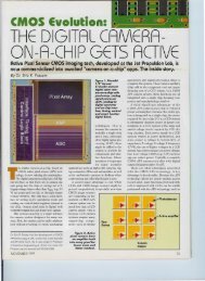
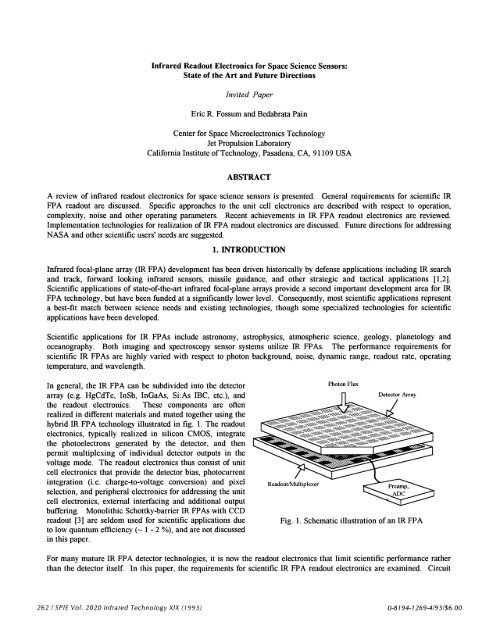
<strong>Infrared</strong> Readout Electronics <strong>for</strong> Space Science Sensors:State of the Art and Future DirectionsJnvited Paper<strong>Eric</strong> R. <strong>Fossum</strong> and Bedabrata PainCenter <strong>for</strong> Space Micro<strong>electronics</strong> TechnologyJet Propulsion LaboratoryCali<strong>for</strong>nia Institute of Technology, Pasadena, CA, 9 1 109 USAABSTRACTA review of infrared <strong>readout</strong> <strong>electronics</strong> <strong>for</strong> <strong>space</strong> <strong>science</strong> <strong>sensors</strong> is presented. General requirements <strong>for</strong> scientific IRFPA <strong>readout</strong> are discussed. Specific approaches to the unit cell <strong>electronics</strong> are described with respect to operation,complexity, noise and other operating parameters. Recent achievements in JR FPA <strong>readout</strong> <strong>electronics</strong> are reviewed.Implementation technologies <strong>for</strong> realization of IR FPA <strong>readout</strong> <strong>electronics</strong> are discussed. Future directions <strong>for</strong> addressingNASA and other scientific users' needs are suggested.1. INTRODUCTION<strong>Infrared</strong> focal-plane array (IR FPA) development has been driven historically by defense applications including IR searchand track, <strong>for</strong>ward looking infrared <strong>sensors</strong>, missile guidance, and other strategic and tactical applications [1,2].Scientific applications of state-of-the-art infrared focal-plane arrays provide a second important development area <strong>for</strong> JRFPA technology, but have been funded at a significantly lower level. Consequently, most scientific applications representa best-fit match between <strong>science</strong> needs and existing technologies, though some specialized technologies <strong>for</strong> scientificapplications have been developed.Scientific applications <strong>for</strong> JR FPAs include astronomy, astrophysics, atmospheric <strong>science</strong>, geology, planetology andoceanography. Both imaging and spectroscopy sensor systems utilize JR FPAs. The per<strong>for</strong>mance requirements <strong>for</strong>scientific JR FPAs are highly varied with respect to photon background, noise, dynamic range, <strong>readout</strong> rate, operatingtemperature, and wavelength.In general, the JR FPA can be subdivided into the detectorarray (e.g. HgCdTe, InSb, JnGaAs, Si:As IBC, etc.), andthe <strong>readout</strong> <strong>electronics</strong>. These components are oftenrealized in different materials and mated together using thehybrid JR FPA technology illustrated in fig. 1 . The <strong>readout</strong><strong>electronics</strong>, typically realized in silicon CMOS, integratethe photoelectrons generated by the detector, and thenpermit multiplexing of individual detector outputs in thevoltage mode. The <strong>readout</strong> <strong>electronics</strong> thus consist of unitcell <strong>electronics</strong> that provide the detector bias, photocurrentintegration (i.e. charge-to-voltage conversion) and pixelselection, and peripheral <strong>electronics</strong> <strong>for</strong> addressing the unitcell <strong>electronics</strong>, external interfacing and additional outputbuffering. Monolithic Schottky-barrier JR FPAs with CCD<strong>readout</strong> [3] are seldom used <strong>for</strong> scientific applications dueto low quantum efficiency (-' 1 - 2 %), and are not discussedin this paper.Photon FluxFig. 1, Schematic illustration of an JR FPAFor many mature JR FPA detector technologies, it is now the <strong>readout</strong> <strong>electronics</strong> that limit scientific per<strong>for</strong>mance ratherthan the detector itself. In this paper, the requirements <strong>for</strong> scientific JR FPA <strong>readout</strong> <strong>electronics</strong> are examined. Circuit262 ISPJE Vol. 2020 <strong>Infrared</strong> Technology XIX (1993) 0-8194-1269-4/93/$6.00
typically obtained in state-of-the-art low background IR FPAs. Lower noise levels have been reported in a few papersdiscussed below. As a rule of thumb, <strong>for</strong> a given focal-plane power dissipation, <strong>readout</strong> noise increases with <strong>readout</strong> rate.There are several noise processes introduced by the <strong>readout</strong> <strong>electronics</strong> 16]. The 1/f noise (sometimes called excess orflicker noise, and whose power spectrum is given by 1/f°, x 1-2) in <strong>readout</strong> unit cell <strong>electronics</strong> is an important issue <strong>for</strong>low background applications involving long integration times (greater than 100 milliseconds). For most unit cell circuitsused in JR FPAs, the input-referred noise electrons due to the 1/f noise is directly proportional to integration time, makingthe JR FPA noise significantly larger <strong>for</strong> longer integration times.Other temporal noise sources that are of concern <strong>for</strong> <strong>readout</strong> <strong>electronics</strong> are transistor white noise (or channel thermalnoise), and reset noise. The effect of transistor white noise can be minimized by reducing the integration capacitances.Reset noise is introduced whenever a switch is used to preset a voltage on a capacitor, and has a voltage r,m.s. value equalto (kT/C)2, where C is the capacitor value, and T is the temperature. This so-called kTC noise can be eliminated bycorrelated double sampling discussed later.Fixed pattern noise (FPN) is associated with randomly distributed, time-invariant offsets in unit cell circuits (in additionto FPN associated with detector arrays). FPN due to gain non-uni<strong>for</strong>mity and non-linearity can ultimately lead to lessthan-BLIPper<strong>for</strong>mance [7]. FPN and temporal noise can also be introduced by on-chip clocking signals used to drive theJR FPA <strong>readout</strong> <strong>electronics</strong>. Careful layout and separation of digital and analog circuits are required to minimizeclocking noise. Low FPN is desirable <strong>for</strong> scientific sensor <strong>readout</strong> <strong>electronics</strong>.Another source of noise is the so-called amplifier glow problem. Due to hot electrons in the output amplifier transistor(s),photons that are approximately at the semiconductor band gap energy are emitted. These photons can travel a significantdistance be<strong>for</strong>e being reabsorbed by the semiconductor, giving rise to a pseudo-dark current (with associated shot noise) inthe general vicinity of the <strong>readout</strong> amplifier. In addition to being absorbed in the <strong>readout</strong> <strong>electronics</strong> circuits, thesephotons can also be sensed by the infrared detectors. In general, reduction of bias currents and voltages can ameliorateamplifier glow.2.4 Dynamic RangeDynamic range is defined as the ratio of the maximum signal that can be integrated to the r.m.s. noise floor. If this ratiois R, then dynamic range is in decibels (dB) is 20 log R. The required dynamic range is determined by the application,and is typically the ratio of the brightest feature to be observed to the weakest. Users prefer the largest possible dynamicrange, but are often limited by either available analog to digital (A/D) converters to under 16 bits (96 dB), by the <strong>readout</strong><strong>electronics</strong> unit cell storage capacitor technology to a lesser value, typically 70-80 dB, or by requirements of linearity,which can be very stringent <strong>for</strong> scientific applications (e.g. less than 1% integral non-linearity).2.5 Readout RateReadout rate is typically related to the allowed on-focal-plane power dissipation <strong>for</strong> high <strong>readout</strong> rates, array <strong>for</strong>mat,integration time, and by practical system considerations <strong>for</strong> low read out rates. For large <strong>for</strong>mat ( 256x256) staringarrays, simple integrate and <strong>readout</strong> JR FPAs often require data rates in excess of 100 kpixels/sec. The data rate can alsobe high <strong>for</strong> JR FPAs operating at LWJR band, where the integration time can be short. Usually, <strong>for</strong> simple integrate and<strong>readout</strong> JR FPAs, <strong>readout</strong> rates of the order of 10-100 kpixels per second are utilized. For JR FPAs with multiple, nondestructivesampling, and <strong>for</strong> high background applications, higher <strong>readout</strong> rates are required. Typically, scientific JRFPA <strong>readout</strong> does not exceed 1 Mpixel/sec.2.6 Operating TemperatureThe operating temperature of the IR FPA is typically set by the detector cutoff wavelength. Longer cutoff wavelengthsrequire colder operating temperatures to reduce detector dark current. Detector dark current introduces additional shotnoise and increases the dynamic range requirement since the dark current integration is summed with the photosignal andthe total charge must be accommodated by the unit cell capacitance. A practical lower bound on the operating264 / SPIE Vol. 2020 <strong>Infrared</strong> Technology XIX (1993)
temperature of the <strong>readout</strong> <strong>electronics</strong> is set by the increase in <strong>readout</strong> <strong>electronics</strong> noise and appearance of several deviceanomalies (such as hysteresis, kinks etc.) at the onset of carrier freezeout. In conventional silicon CMOS, this takes placeat temperatures below approximately 50 K. SIRTF and many LWIR scientific <strong>sensors</strong> require operation at sub-10Ktemperatures, posing a challenge in the design and realization of low noise <strong>readout</strong> <strong>electronics</strong>. In general, users tradeoperating temperature <strong>for</strong> IR FPA per<strong>for</strong>mance since a lower operating temperature increases system cost.2.7 PowerMost users would prefer to have no power dissipated on the focal-plane. The allowed power dissipation is determined bythe cryogenic cooling apparatus. Typical power levels range from sub-milliwatt to a few tens of milliwatts. Most of thispower is dissipated by the final output amplifier stage in the <strong>readout</strong> <strong>electronics</strong> since it must drive a large cablingcapacitance at a relatively high data rate. (Loral has demonstrated a low power highly linear output buffer amplifier usingsignal dependent adaptive biasing techniques. The buffer amplifier is reported to have achieved less than 0. 1% integralnonlinearity and 900 kHz unity gain frequency while dissipating only 125 W of power [8]). Additionally, if the <strong>readout</strong><strong>electronics</strong> is operated warmer than the detector, heater power required to maintain the <strong>electronics</strong> at a warmertemperature must be included as well.2. 8 Radiation HardnessTwo types of radiation hardness are considered. These are total dose hardness and ionizing radiation hardness, Totaldose causes threshold voltage shifts and a possible increase in noise ultimately resulting in FPA <strong>readout</strong> <strong>electronics</strong>failure. Cosmic rays and other high energy particles and photons result in "salted't images that are a problem <strong>for</strong> longintegration periods in <strong>space</strong>-based IR FPAs. Since defense applications generally require higher radiation hardness levelsthan scientific applications, the scientific radiation hardness requirement is not often a limiting one.2.9 Detector Bias ControlThe detector bias during photocurrent integration can affect the dark current, injection efficiency, detector 1/f noise, andresponsivity. The dynamic resistance R, and device area A product (R€A) is used to measure the susceptibility of thedetector array to dark current and injection efficiency effects. RA values typically decrease at longer cutoff wavelengths,causing a reduction in the injection efficiency and introducing non-linearity in the response of JR FPA [9]. To alleviatethe problem of reduced injection efficiency and concomitant increased non-linearity, a tight control of detector bias isrequired during integration. LW1R detectors typically benefit from a constant bias during integration with control of theorder of millivolts. For less mature detector technologies, detector 1/f noise can be affected by bias voltage so thatconstant bias is desired. In photoconductors, including superlattice devices, the bias voltage can affect the responsivity ofthe detector so that constant bias is also desired <strong>for</strong> these detectors.2. 10 Array Size and PitchAs a rule of thumb, scientific users generally prefer high resolution leading to large arrays sizes and small pixels. Arraysize and pixel pitch is often limited by the hybrid IR FPA technology. This limits detector pitch to approximately 30microns due to bump bond size, and array size to 5 12x512 <strong>for</strong> practical yield considerations. Larger array sizes(1024x1024) are under development and smaller pixel pitches have been demonstrated in limited quantity. In general, thearray size tends to decrease with increasing wavelength of operation mainly due to an absence of large detector array<strong>for</strong>mats in less mature materials used <strong>for</strong> longer cutoff wavelengths. Larger pixel pitches are desirable <strong>for</strong> integratingmore sophisticated unit cell <strong>electronics</strong>. Larger pixels are also required at longer wavelengths due to the increase in thediffraction limit with increasing wavelength.3. CIRCUIT APPROACHES FOR READOUT ELECTRONICSIR FPAs are operated both in staring mode and scanning mode. With the maturing of an IR detector technology nowcapable of yielding large <strong>for</strong>mat detector arrays, staring mode JR FPAs have become common. However, scanning JRSPIE Vol. 2020 <strong>Infrared</strong> Technology XIX (1993)! 265
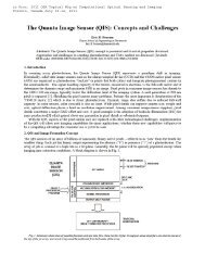
FPAs are often used in several applications such as earth observing satellites in which the sensor is airborne and movingwith respect to the earth. We will attempt to describe state-of-the-art per<strong>for</strong>mance of both types of arrays used inscientific applications.Micro<strong>electronics</strong> feature size has steadily decreased over the past few decades enabling increasingly sophisticated unit cell<strong>electronics</strong> design. Simple unit cell <strong>electronics</strong>, such as the source-follower per detector (SFD) approach, continue to beattractive because of the achievable small pixel pitches and low power dissipation. More complex unit cell <strong>electronics</strong>utilizing high gain amplifiers are gaining in acceptance and provide excellent bias control, linearity and noiseper<strong>for</strong>mance. A comparison of the per<strong>for</strong>mance characteristics of different types of unit cell circuits is shown in table 1.We now attempt to summarize some of the more common approaches to unit cell design.3 . 1 Source-Follower Per Detector (SFD)The source follower per detector unit cell is shown in fig. 2. The unit cell consists of an integration capacitance (Cint), areset transistor (Mrst) operated as a switch, the source-follower transistor (M1), and one or more selection transistors.The integration capacitance may just be the detector capacitance and source-follower input capacitance. If A is the gain ofthe source-follower (A < 1), the photoelectron charge-to-voltage conversion is A(q/C) measured in volts per electron.The cell dissipates no active power during integration. The integration capacitance is reset to a reference voltage bypulsing the reset transistor. The photocurrent is then integrated on the capacitance during the integration period. As thesignal is integrated, the detector bias changes since the signal is integrated directly on the same node as the detector. Forlarge detector capacitances, the voltage-dependent integration capacitance of the detector can result in non-linear chargeto-voltageconversion limiting the usable dynamic range <strong>for</strong> scientific applications. Readout is achieved by selecting thecell and reading the output of the source-follower. The cell is susceptible to threshold voltage non-uni<strong>for</strong>mities leading tofixed-pattern noise (FPN), and to kTC noise unless correlated double sampling (CDS) is used. Since SFD consumes verysmall real estate, SFD <strong>readout</strong> is often designed to include a CDS circuit in the unit cell.rst'detVddselThe main source of white noise in the SFD unit cell is thesource-follower transistor itself. The input-referred whitenoise electrons is given by:kT Hintc + 217iflt 1R0 j/ N2\ —mt\ 1 whitewhere CL is the load capacitance which the source-follower isrequired to drive, Tint is the integration time, and thesaturation frequency (sat) is given by: fsat=l/(2rtRCjnt).VdetC Since SFD is used in applications where the detectori: bus resistance (R0) is extremely small, the detector white noisecontribution to the <strong>readout</strong> noise is negligible. If the loadcapacitance is much larger than the integration capacitance(usually the case, since it is dominated by the multiplexer buscapacitance), low noise per<strong>for</strong>mance is possible by allowingFig. 2. Schematic of source-follower per detector Cint to be small. However, SFD topology is particularlyunit cellsusceptible to 1/f noise. This is due to the fact that, unlikeother unit cell <strong>readout</strong> circuits, the time period <strong>for</strong> which the source-follower transistor is turned on during multiplexing islonger than the response time of the source-follower. The effect of this is to enhance the low frequency noise contribution,an effect that has been reported by various authors I lOJ.SFD has been used as the unit cell <strong>for</strong> several IRFPAs such as NICMOS3, JR FPAs to be used <strong>for</strong> MWIR and LWIRSIRTF applications as well as <strong>for</strong> MWIR ground-based telescopes. Cincinnati Electronics, Hughes and Rockwell havedemonstrated 256x256 SFD <strong>readout</strong>s [11,12,13]. The Hughes SFD <strong>readout</strong> is designed to operate both with InSb andSi:As impurity band conductor (IBC) detectors operating at sub 10K over a spectral range of 5-28 .tm. Since the Hughes266 I SPIE Vol. 2020 <strong>Infrared</strong> Technology XIX (1993)
eadout is designed <strong>for</strong> background charge as high as 14,000 electrons (required by SIRTF at 12 tm band), the integrationcapacitance cannot be made very small. However, the required data rate is low, allowing the use of multiple samplingtechniques to reduce broad band noise. The noise per<strong>for</strong>mance of the Hughes <strong>readout</strong> has been shown to be stable at lowtemperature (< 10K) [14]. The Cincinnati Electronics SFD <strong>readout</strong> uses an InSb detector and is capable of operation from4K - 77K, with the noise increasing rapidly below 15 K [151. A maximum data rate of 400 kHz has been achieved inthese JR FPAs.TABLE IComparison of Per<strong>for</strong>mance Characteristics of Different types of Readouts used in IR FPAsNumber of 3Transistors perUnit CellSm DI ED! GMI CTIA2 4 <strong>for</strong> ordinaryinverter in cell;5 <strong>for</strong>_cascode3 7 <strong>for</strong> duff. amp.;4 <strong>for</strong> cascode amp.Max. Intg. Time RijCj 1oCintAvm RtjC/(1+gpjRtj) A0LjCjMm. Intg. Time RC/(l+gjR,) RCd/A0(l+gjR)2aOperating limited by powerFrequency . . .dissipation and dataratelow, <strong>for</strong> r 1smallest < 1 IFNoise low-medium noise minimum limited by a large Chiic low noise low noiseBias Control none minimal very good minimal very goodFPNmoderate due to VTnonuni<strong>for</strong>mitylow low high due to biasinstability and VTnonuni<strong>for</strong>mityPower low low medium low to medium medium to highThe Rockwell SFD <strong>readout</strong> (NTCMOS3) has been used in several SWIR and MWIR astronomy applications and operatedat 77 K with PV HgCdTe detectors. Rockwell has also operated JR FPAs at 175 K using SWIR InGaAs/JnP detectors anda SFD unit cell [161. Work is underway in Rockwell to increase the NICMOS3 array size to 5 12x5 12 with a 25 tm pitchand a predicted read noise of less than 4 electrons [7]. NICMOS3 uses an off-chip CDS to reduce the reset noise and the1/f noise [17]. The relevant operating characteristics of SFD <strong>readout</strong>s built by Cincinnati Electronics, Hughes andRockwell are summarized in table 2.lowSPIE Vol. 2020 <strong>Infrared</strong> Technology XIX (1 993) I 267
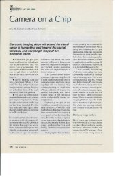
Type Format Pitch(jtmxjtm)TABLE IIPer<strong>for</strong>mance of Selected Readout ICs <strong>for</strong> Scientific ApplicationsC1(if)T.tNoise(e)SFD 256x256 30x30 ? 10-100 s 55 10K48 @ 50KSFD 256x256 30x30 270 > 150 ms 700 @ 4K186@77K60 @ 77KData Rate Company Comments(kHz)> 6.5 Hughes MCS used< 400 Cincinnati 60 e noise withMCDSSFD 256x256 40x40 60-85 10 ms 19-40 @ 7K < 300 Rockwell off-chip CDS usedCAD 1x32 ? 2200 10 sec 10 @ 20K ? Amber MCS usedBDI 30x92 50x100 ? 3 12 ts 80 @ 67K 300 WestinghouseTDIGMI 128x128 60x60? 40 22 ms 4.8 @ 200K ? Rockwell Current gain> 47000CTIA 260x1 25x? 30 42 ts 120 67K < 6500 Hughes in-pixel CDSCTIA 32x134 50x50 10 42 ts 1.9 @ 67K < 3200 SBRC in-pixel CDS;167s 7@67KmlCTIA 10x132 25x75 4 25 ts 3.3 145K < 5000 Rockwell in-pixel CDS;mlCTIA 128x128 50x50 4 20 ms 3.4 78K ? Rockwell in-pixel CDS3.2 Direct Injection (DI)A typical direct injection unit cell is shown in fig. 3. Theunit cell consists of an integration capacitor (Cint), aninjection transistor (M1), a reset transistor (Mrst) and anoutput selection transistor. The cell is operated by firstresetting the integration capacitor by pulsing the resettransistor. Photocurrent from detector is then integratedon the integration capacitor through the injectiontransistor. Since the photocurrent is input through theinjection transistor, the DI scheme yields somewhat betterbias control during integration compared to SFD.Following integration, the capacitor is selected and itsintegrated charge dumped on to the column selection line.The photoelectron charge-to-voltage conversion is simplymeasured in volts per electron. The celldissipates no active power during integration as in thecase of the SFD. An important per<strong>for</strong>mance parameter inthis circuit is injection efficiency (i). Injection efficiencymeasures the fraction of the detector photocurrent that is11= gR01 +'detVbiC busMUX BUSFig. 3 . Schematic of a direct injection unit cell circuit.coupled to the <strong>readout</strong> circuit and is defined as the ratio ofphotocurrent integrated on Cint to the total detector photocurrent. Low r is caused by low detector impedance (Re),providing a parasitic path <strong>for</strong> current flow. From the definition of the injection efficiency, it can be expressed as:CdetVddHrst268 ISPIE Vol. 2020 <strong>Infrared</strong> Technology XIX (1993)
where gmj S the transconductance of the injection transistor and R is the small signal resistance of the detector. Sincethe magnitude of the photocurrent is small, the injection transistor is biased in weak inversion, making its gm relativelysmall. For detectors with longer cutoff wavelengths, R reduces drastically (R can be as low 1 M) <strong>for</strong> a HgCdTe PVdetector with cutoff wavelength of 12 .tm), reducing the injection efficiency as well as making the injection efficiencyphotocurrent dependent. As a result, this circuit is less desirable <strong>for</strong> unit cell <strong>readout</strong> in JR detection in LWJR or beyond.Further, the injection efficiency is a function of frequency with a relatively small cutoff frequency, thereby limiting thecircuit's ability <strong>for</strong> high frequency (small integration time) operation [3].One of the problems of using injection-transistor-based <strong>readout</strong> circuits is that their per<strong>for</strong>mance degrades severely inapplications with low backgrounds. The transconductance of the injection transistor decreases in proportion with thebackground photocurrent, causing a degradation of injection efficiency, and making the injection transistor noisesubstantially large. The problem is further exacerbated by the increased demands on the d.c. bias stability of the injectiontransistor. There<strong>for</strong>e, a DI circuit is not preferred <strong>for</strong> operation in ultra-low background applications, as well as withdetectors having longer cutoff wavelengths (exhibiting small detector resistance).The maximum integration time is limited by the saturation frequency (sat) related to the integration capacitance (Cint)and resistance (R0) and is given by: fsath/(2intRoAvm), where A=gj/g5j, and gdsi is the output conductance ofthe injection transistor. The saturation frequency is lower than in SFD due to a certain degree of bias control offered bythe injection transistor. Compared to SFD, this cell is less susceptible to FPN, but still suffers from reset noise unlessexternal double correlated sampling is used. Ignoring the reset noise, it can be shown that the input-referred noiseelectrons is given by:(N2\ =21tTi+ 1\ 'white q2 R0 )[ gjR0I \ 2T2 ( 2c N 1/f q2 5fd gR0 ) 5fm 1nwhere 5fd and 5fm are the respective detector and injection transistor current 1/f noise power spectral densities at 1 Hz.Larger values of the integration capacitance (Cint) results in a larger input-referred noise <strong>for</strong> a given output noise power,while the output noise power itself is inversely related to Cint (since a larger Cint increases the noise bandwidth), therebymaking the noise independent of Cint, as indicated by the equation shown above.During multiplexing, the charge integrated on Cint is shared with the bus capacitance. There<strong>for</strong>e, DI circuits are usuallydesigned with large integration capacitors to prevent degradation of signal due to charge sharing, at the cost of reducedcharge sensitivity of the input circuit. Further, the presence of a large bus capacitance makes input-referred downstreamnoise (such as multiplexer noise, output driver noise, and clocking noise) large, since input-referred noise electrons due todownstream noise is given by:KN2)white= V2 (C + Cbus)where vnout is the r.m.s. downstream voltage noise, and Cbus is the bus capacitance. For a typical r.m.s. downstreamnoise of 25 pvolts, fig. 8 indicates that the downstream noise is dominant in DI, especially <strong>for</strong> smaller integrationcapacitance sizes, limiting the minimum noise floor to a higher value compared to SFD or CTIA.DI circuits are usually not used <strong>for</strong> scientific applications since a slightly modified circuit, called buffered direct injectioncircuit, exhibits much improved injection efficiency, and higher frequency operation capability.SPIE Vol. 2020 <strong>Infrared</strong> Technology XIX (1993) / 269
3.3 Buffered Direct Injection (BDI)Buffered direct injection 1181 is similar to direct injection except that inverting gain is provided between the detector andthe injection transistor gate, as shown in fig. 4. The gain can achieved, <strong>for</strong> example, by using a simple inverter circuit.The inverted gain provides feedback to yield better control over the detector bias at different photocurrent levels. As thephotocurrent increases, the input impedance of the injection transistor is decreased to maintain constant detector bias.The photoelectron charge-to-voltage conversion is still q/C measured in volts per electron. The cell now dissipatesactive power in the amplifier during integration. The injection efficiency (Ti) is improved compared to the direct injectioncase to:gmi(l Avo)Rol+gj(l+A0)R0where Avo is the low frequency gain of the inverting amplifier. Further, compared to a DI circuit with the same R0, Cjntand Cd, the cutoff frequency of the injection efficiency in BDI increases by (1+Ao), allowing much higher frequencyoperation of the unit cell.MUX BUSHC ṁtCdetVdet1VddFig. 4. Schematic of a buffered direct injectionunit cell circuit.Apart from an improvement in the injection efficiency, the inverting gain also helps to reduce the saturation frequencycompared with the DI circuit, thereby allowing longer integration times. The saturation frequency of a BDI circuit isgiven by: fsath/(2vmAvoPoCint), and is much smaller compared to the saturation frequency of DI and SFD. InBDI, improved injection efficiency, reduced saturation frequency and tighter bias control is achieved at the cost ofincreased power dissipation and added unit cell complexity. However, the inverting amplifier can be designed to operateat sufficiently low power, since it is required to drive only a small capacitance (approximately the gate capacitance of theinjection transistor).In spite of the increased injection efficiency achieved by BDI, it shares the same limitation with DI in terms of its use inultra low background applications, since the injection transistor has to operate at extremely low drain currents. The inputreferrednoise electrons of a BDI circuit (neglecting downstream noise and reset noise) is given by:270 / SPIE Vol. 2020 <strong>Infrared</strong> Technology XIX (1993)
I 2' kT(T 1 1(N ; =2—I—---l1+ +\ I white q2 R0 ) gjR0A2 gR0KN2)=2T2t[+Sfm[) +where gma is the transconductance of the amplifier, and Sfa is the amplifier input-referred 1/f noise power spectraldensity at 1 Hz. Due to the tighter bias control achieved by feedback in BDI, BDI unit cell white noise is smaller than thatof DI. However, typically, similar to a DI circuit, the input-referred noise is dominated by bus capacitance. BDI is mostsuited <strong>for</strong> high background applications, that require larger charge storage capacity, larger integration bandwidth, andmoderate <strong>readout</strong> noise.Westinghouse has built scanning MWIR JR FPA <strong>for</strong> high background applications, using wide bandwidth BDI unit cellcoupled to high dynamic range CCD with an additional blooming control circuit [2]. The unit cell pitch is 50 rim, and thearray consists of 92 column and 30 ThI stages. For 3 12.5 sec. integration time, the unit cell read noise has beenmeasured to be less than 80 electrons. The maximum charge storage capacity of each unit cell is less than 1x10⁵electrons.3.4 Gate Modulation Input (GMI)A gate modulation input circuit [19,20] is shown in fig. 5. A load device, typically a load transistor (M1), is placed inseries with the detector. The bias voltage developed across the load is used to modulate the gate voltage of an outputtransistor (Me). The output transistor and the load transistor are usually connected in current mirror-like configuration,with the respective source voltages V55 and Vbias adjusted <strong>for</strong> setting the current gain. The input transistor discharges acapacitor previously reset to a reference level. The photoelectron charge-to-voltage conversion in volts per electron isq g Rmo 0given by, where grno is the transconductance of the output transistor, and gmi is the transconductanceCint l+gjR0of the load transistor. Since the detector current flowing through the load transistor is much smaller than that in theoutput transistor, GMT circuit yields a large charge-to-voltage conversion gain compared to DI and BDI circuits. Theincreased current gain leads to higher charge detection sensitivity and reduced input-referred noise levels. The inputreferrednoise electrons <strong>for</strong> GMI is given by:IN2') =+miRo)[1+gjR0 A2 gjR0\ 'white q2 L R0 J[ g0R0 jvog0R0 Cd )22/ \2 I \2 7I 2 \ _ 'int I 1 + —gjR0 ' ' 2 1 Cint IN ,, I i 5fd +Sfm)A I\ I 5fo in1I 1/fvoq g0R0 ) Cd ,11mnt'satwhere 5fo is the output transistor drain current flicker noise power spectral density at 1 Hz, A0=g0/g50, andThe saturation frequency of GMI is higher than that achieved with DI and BDJ <strong>for</strong> a given Cdand thereby limiting the integration time. GMI can potentially yield very low input-referred noise due to the intrinsiccurrent gain that can easily be as high as iO' in medium to low background applications. Because of the large unit cellcurrent gain, GMI can operate with a larger integration capacitance compared to DI and BDI, and still obtain low noiseper<strong>for</strong>mance and high charge sensitivity. Fig. 8, which illustrates the dependence of the input-referred noise electrons onthe integration capacitance, indicates that GMI has the best white noise per<strong>for</strong>mance <strong>for</strong> a wide range of integrationcapacitance size (1 fF - 1 pF). The noise floor is limited by the detector noise to about 3 electrons r.m.s., <strong>for</strong> anintegration time of 10 msec. and detector dynamic resistance of 1014 çSPIE Vol. 2020 <strong>Infrared</strong> Technology XIX (1993) / 271
The GMI is susceptible to FPN due to thresholdvoltage variations in the input transistor causing theVddcurrent gain to vary from one cell to another. Further,<strong>for</strong> low noise operation of GMI, source biases of bothCdetthe load transistor and the input transistor requireexcellent bias control within 1 ppm. (to be providedi— i rstexternally) [2 1]. In spite of these stringent operatingrequirements, excellent noise per<strong>for</strong>mance has been "Idemonstrated by Rockwell using a 128x128 <strong>for</strong>mat 'detGMI <strong>readout</strong> mated to a InGaAs detector with 1.7 tmcutoff wavelength under low background [10]. Thecurrent gain was greater than 47000 and inputreferrednoise was measured at 4.8 electrons <strong>for</strong> a 22selmsec. integration time and 40 fF of detectorcapacitance.MUXBUSVssOne unique feature of GMI is that the current gainCv,iasbusself adjusts depending upon the background flux,since the current gain is approximately proportionalto the detector current level. The self adjusting gainFig. 5. Schematicofa gate modulationfeature can be used <strong>for</strong> background pedestalinput umt cell circuitsuppression leading to higher dynamic ranges, andhas been used by Rockwell to obtain dynamic range greater than 200 dB, albeit at the cost of increased non-linearity andfixed pattern noise [22].3.5 Cascode Amplifier Per Detector (CAD)Like the gate modulation input circuit, the cascode unit cell amplifier provides <strong>for</strong> increased photoelectron charge-tovoltageconversion, thus raising the unit cell output signal above a system noise floor, and making it much easier to avoidsystem noise degradation from subsequent stages. Conversely, <strong>for</strong> a given downstream noise level, integration time issmaller than SFD, yielding better bias control, required <strong>for</strong> longer cutoff wavelength detectors. The cascode unit cellamplifier is shown in fig. 6. The unit cell consists of an integration capacitance (Cint), a reset transistor (Mrst) operatedas a switch, the cascode amplifier transistors (M1, Mcasc, ML), and one or more selection transistors. The cascodeamplifier is an inverter with a cascode transistor (Mcasc) inserted to reduce the Miller capacitance and keep the inputcapacitance low (required to maintain high detection sensitivity). The load of the cascode inverting amplifier consists of atransistor (L) If silicon CMOS is unavailable, ML is of the same type as M, so that the voltage gain, A, of the cascodeamplifier circuit is given by the ratio of the input transconductance (gmi) to the load transconductance (g) and isexpressed as:A=--=1gmLi()\i LLwhere W is the gate width and L is the gate length. The voltage gain is relatively small (limited to about 10) since it isdependent on the ratio of the transconductances, but is independent of threshold voltage and bias current variations.Apart from providing voltage gain, SFD and cascode amplifier unit cell are remarkably similar in per<strong>for</strong>mance, and thecomments made earlier about the per<strong>for</strong>mance of SFD holds <strong>for</strong> the cascode amplifier unit cell as well.272 / SPIE Vol. 2020 <strong>Infrared</strong> Technology XIX (1993)
stVddFig. 6. Schematic of a cascode amplifier per detectorunit cell circuit.3.6 Capacitive Transimpedance Amplifier (CTIA)Amber Engineering has constructed and fabricated a1x32 cascode <strong>readout</strong> and multiplexer (AE-152) <strong>for</strong> usein SIRTF far-infrared (50-120 m) instruments withGe:Ga photoconductor detector arrays [23]. In order tocancel the offset introduced by threshold shifts in the unitcell, the unit cell also includes a DC restore circuit with a20 pF coupling capacitance from the cascode unit cell tothe unit cell source follower. Typical power dissipationis low, since each unit cell conducts current only 1/32 ofthe frame time, and is measured to be 156 .tW <strong>for</strong> all the32 channels. Operated above 20 K AE-152 has a readMUX BUS . .noise of 10 electrons <strong>for</strong> a large integration capacitanceof 2.2 pF. The low noise per<strong>for</strong>mance was achieved byTconstructing the signal with multiple slope samplingtechnique using 4 samples per channel, and 10 sec. longintegration times. Since only 32 unit cells occupy thefocal-plane, the transistors are designed with largedimensions, thereby reducing 1/f noise. However, theheater power is an additional heat burden, since AE-152operates at 20 K, while the photoconductor detectorarrays requires to be operated at less than 2 K 1241.The capacitive transimpedance amplifier is shown in fig. 7. The CTIA consists of an inverting amplifier with a gain of A,an integration capacitance (Cint) placed in a feedback ioop, a reset transistor (Mrst) in parallel with the integrationcapacitance, and one or more selection switches. The inverting amplifier is usually a cascode amplifier implemented in asingle input or differential input topology. While a single CMOS inverting amplifier is attractive because of real estatereasons, the differential amplifier topology offers superior power supply noise rejection and bandwidth control, which isimportant <strong>for</strong> power and noise optimization.At the outset of photocurrent integration, the integrationcapacitance is reset to a reference voltage (generated by theamplifier) by pulsing the reset transistor. During theintegration mode of operation, the photocurrent is integratedalmost solely on the integration capacitance, while thefeedback and the large gain of the amplifier holds the input atthe virtual ground, thereby almost entirely preventing anycharge integration on the detector capacitance. Since the inputis pinned to the virtual ground, a tight control on the detectorbias is maintained, facilitating its use with detectors havingrelatively small R0 (detectors with longer cutoff wavelengths).Since the output of the unit cell is connected to a lowimpedance node (the amplifier output), the integrationcapacitance of CTIA, unlike that of DI, BDI and GMI, can bemade extremely small, yielding excellent low noiseper<strong>for</strong>mance. However, the high detection sensitivity and lownoise is achieved at the cost of increased power dissipation andunit cell pitch. The photoelectron charge-to-voltageconversion is+C+Cdse1C busmeasured in volts per electron,IdetVdetrstICdetIselMUXBUSC busIFig. 7. Schematic of a capacitive transimpedanceamplifier unit cell.SPIE Vol. 2020 <strong>Infrared</strong> Technology XIX (1993)! 273
with A0 being the amplifier gain. As a result of the feedback, the effective saturation frequency of CTIA is decreasedcompared to that of SFD, and is given by:satC +C2voRo[Cint + ivod JCTIA is used <strong>for</strong> low noise, large bandwidth applications since the smallest integration time is limited by the unity gainfrequency of the amplifier. However, there is a trade-off between operating with a small integration time and focal-planepower dissipation.Ignoring the reset noise and the downstream noise (small <strong>for</strong> a low value of integration capacitance), the input-referrednoise electrons of CTIA is given by:KN2)white+ [Cjflt+CdCL +Ci+Cd]Cint +2T2 mt1KN2) 1/f q2 Sfdli{ sat"7int a "5)f)2lnhIIll.8fawhere Sfa is the amplifier 1/f noise drain current power spectral density at 1 Hz, a is the cutoff frequency of the amplifier,and typically limits the shortest integration time. CTIA input-referred noise is independent of amplifier gain, providedthe gain is large. The input-referred noise can be made small by making the integration capacitance small, whileincreasing the load capacitance at the same time to decrease the amplifier noise by reducing the noise bandwidth. Fig. 8indicates that CTIA white noise per<strong>for</strong>mance is slightly inferior to that of GMI <strong>for</strong> a given capacitance. However, GMIintegration capacitance cannot be made very small in practice because of the limitations imposed by bus charge sharing,while CTIA integration capacitance can be made as small as 1 fF, leading to ultra low noise per<strong>for</strong>mance.CTIA unit cells have been applied in a wide variety of circumstances and both in staring and in scanning modes. In earlyef<strong>for</strong>ts, 10 electron read noise was reported by Rockwell and Amber using a CTIA unit cell that was operated at 92 K [25J.Honeywell reported obtaining 70 electron read noise using CTIA unit cell and integration times as high as 100 seconds[26] <strong>for</strong> SWIR applications. With further advancements in IR detector technology, some of the lowest noise per<strong>for</strong>mancehave been achieved with CTIA as the <strong>readout</strong> unit cell, especially by incorporating a unit cell CDS circuit.Rockwell has demonstrated a SWIR JR FPA with an ultra low noise CTIA-CDS unit cell operated at very lowbackgrounds (< 106 photons/cm2/sec) in 1282 <strong>for</strong>mat 1101. The CTIA was biased at subthreshold in order to reducepower. With a 4 IF integration capacitance, 23 fF detector capacitance, 1.5 pF load capacitance, and a nominalintegration time of 20 msec., the read noise was measured to be 3.4 electrons. Rockwell has also demonstrated a highper<strong>for</strong>mance SWIR lOx 132 scanning IR FPA with a "sidecar" architecture. The unit cell consists of CTIA and CDS, andthe "sidecar" TDI stage is implemented with a (10x3)x132 CCD. The unit cell dimensions are 25x75 m2, A novelfeature of the CTIA is that no explicit integration capacitance was added to the unit cell. The integration capacitance274 / SPJE Vol. 2020 <strong>Infrared</strong> Technology XIX (1993)
consisted of the parasitic capacitance, contributed by the gate to drain of capacitance of the input FET and was smallerthan 1 IF, resulting in a high CTIA charge sensitivity of 200 tV/electron, and enhanced low noise per<strong>for</strong>mance. Becauseof the increased charge sensitivity, the downstream noise (e.g. in the CCD) was insignificant. The <strong>readout</strong> noise wasmeasured to be 9.4 electrons per TDI stage with 10 transfers, which translate to input-referred noise of less than 3electrons per CTIA unit cell [27J.Cincinnati Electronics is in the process of delivering an JR FPA <strong>for</strong> low background Visible and <strong>Infrared</strong> MappingSpectrometer (VIMS). The JR FPA uses CTIA unit cell and is expected to achieve
times, reaching as low as 1.88 electrons <strong>for</strong> the smallest integration time of 42 tsec. SBRC LWIR low background, highspeed, high sensitivity JR FPA was built as linear array with 260 elements and 25 m pitch [3 1]. Using a 30 ifintegration capacitance, and <strong>for</strong> an integration time of 42 isec., less than 120 electrons input-referred noise was obtainedat 65K operating temperature. The per<strong>for</strong>mance characteristics of a few selected CTIA <strong>readout</strong>s are presented in table 2.4. NOISE REDUCTION STRATEGIESIn this section, we present various noise reduction schemes that are used with JR FPAs. Most of the noise reductionschemes are complicated in implementation, and are usually carried out digitally off-chip.4. 1 Correlated Double Sampling (CDS)Correlated double sampling virtually eliminates kTC reset noise by measuring the output after the reset, and the outputwith the integrated signal, and computing the difference between the two [32], as shown schematically in fig. 9a. CDScan be implemented in the unit cell as a clamp-and-sample circuit. A clamp-and-sample circuit uses an a.c. coupledcapacitor in the unit cell to remove the amplifier offset (including reset noise) level. CDS is also implemented off-chip bycollecting two digital samples from the sense node, one representing the reset level and another, the level after thephotocharges have been integrated. Since the signal is generated by computing the difference of two data samples, CDScan also reduce 1/f noise and FPN, albeit at the cost of increased white noise contribution.The per<strong>for</strong>mance of the CDS circuit depends on the product of the correlation time (tc), defined as the time intervalbetween the collection of two data samples, and the output amplifier cut-offfrequency (f0) [33]. For a large tcfo, crosstalk and reset noise is reduced but the white noise and 1/f noise is increased. Since the correlation time is the same as thepixel integration time <strong>for</strong> most JR FPAs, the CDS scheme used in IR FPAs is constrained to operate with large ? values inlow background applications. There<strong>for</strong>e, the 1/f noise reduction potential of CDS in JR FPAs is somewhat limited,especially when the integration time is long, while the data rate is high.A modified CDS is often used to improve the 1/f noise reduction characteristics of a CDS circuit used in low backgroundJR FPAs. Jn the modified CDS circuit 1341, two sets of closely <strong>space</strong>d double samples are collected as shown in fig. 9b.Prior to photocurrent integration, the reset noise and the offset is measured by computing the difference between the resetlevel be<strong>for</strong>e and after the reset transistor is shut off. The signal, corrupted by the reset noise and offset, is measured at theend of the integration period by computing the difference between the data level be<strong>for</strong>e and after the unit cell is reset.Since the resultant correlation times are much smaller, superior 1/f reduction is achieved, while the white noiseapproximately doubles compared to simple integrate and read approach, and the power dissipation increases due toincreased data rate. The modified CDS has been used by Cincinnati Electronics in their 256x256 InSb JR FPA operatingbetween 4 -77 K, in order to reduce the excess noise [91.4.2 Multiple Correlated Sample Read (MCS)The analog multiplexer in the IR FPA <strong>readout</strong> can sometimes become a major contributor of noise, resulting fromspurious capacitive coupling. The multiplexer noise which is also dependent on the clocking scheme, can be as high as400 noise electrons even <strong>for</strong> a small 58x62 array [35]. For reduction of this clocking noise, multiple correlated sampling(MCS) technique has been suggested. In the MCS technique (illustrated schematically in fig. 9c), the signal is nondestructively sampled multiple times both at the beginning and at the end of the integration time. Jf a total of 2N samplesare collected, the signal to noise ratio improvement is approximately square root of N. For a 2OO sample MCS, 10electron read noise has been achieved [24]. One obvious disadvantage of this method is the vastly increased data rate,limiting its use <strong>for</strong> large <strong>for</strong>mat, high data rate JR FPAs.4.3 Non-Uni<strong>for</strong>mity Calibration (NUC)hR FPAs, like most other scientific <strong>sensors</strong>, require pixel by pixel calibration to eliminate the effects of both detector and<strong>readout</strong> <strong>electronics</strong> non-uni<strong>for</strong>mities. For example, both signal offset and gain vary from pixel to pixel. Unlike many276 / SPIE Vol. 2020 <strong>Infrared</strong> Technology XIX (1993)
- Trst< _3V = V - Vcds r sFig. 9aSchematic showing CDS <strong>readout</strong> data construction.Trst Trst< Tt >v = (v - vmcs ri SiFig. 9cSchematic showing MCS <strong>readout</strong> data construction.SPIE Vol. 2020 <strong>Infrared</strong> Technology XIX (1993)! 277
DoD applications where one or two-point non-uni<strong>for</strong>mity correction is per<strong>for</strong>med in real-time, non-uni<strong>for</strong>mity calibrationin scientific applications is often per<strong>for</strong>med with many data points both on the ground and sometimes in flight. Thecalibration is applied to the sensor data on the ground to minimize on-board data processing requirements. Futuremissions may benefit from on-board non-uni<strong>for</strong>mity calibration to enhance the compressibility of the data and to enableon-board feature extraction.4.4 Chopper-Stabilized Input Circuits (CSI)Chopper-stabilized unit cell circuits offer two significant improvements over conventional linear amplifiers: effects ofMOSFET threshold mismatch is vastly reduced and 1/f noise per<strong>for</strong>mance of the amplifier is improved. The chopperstabilized unit cell consists of a modulator that translates the input signal to higher frequency where the 1/f noise is low.Since the carrier amplifier is ac. coupled, d.c. offset components are removed. The output of the unit cell is thendownconverted in frequency by using synchronous demodulation. Amber Engineering has demonstrated operation of achopper-stabilized focal-plane <strong>readout</strong> in a 100 m pitch, dissipating
using conventional CMOS processes. Higher speed, lower leakage currents and higher subthreshold slope are the majorbenefits of operating CMOS at 77 K. Thus, there has been recent commercial interest in operating CMOS at 77 K,irrespective of any need to operate an IR FPA at low temperature.The smaller the design rule, the more circuits can be implemented within a given pixel pitch, or conversely, the smallerthe pixel pitch can be <strong>for</strong> a given circuit design. Several CMOS foundries offer processes at design rules down toapproximately 0.8 .tm, though many FPA <strong>readout</strong> circuits are designed with 2 m or 1.2 m CMOS. One reason is thatradiation-hard CMOS circuit technology tends to lag behind mainstream CMOS and generally has larger design rules.Another reason is that CMOS foundries catering to the needs of the aero<strong>space</strong> community have a lower production volumethan commercial foundries, and are thus undercapitalized and understaffed <strong>for</strong> state-of-the-art fabrication. It should benoted that a 5 12x5 12 <strong>readout</strong> <strong>electronics</strong> IC with 40 m pitch utilizing CTIA circuits is over 2 cm x 2 cm in size,andcontains over 2 million transistors and thus requires VLSI fabrication capability.At temperatures lower than 77 K, carrier freeze out becomes increasingly important. A transition in process technologyfrom conventional CMOS to cryogenic CMOS must be made <strong>for</strong> temperatures below approximately 50 K. ConventionalCMOS begins to exhibit some excess noise at these temperatures, but more importantly, hysteretic behavior and kinksdominate in large signal per<strong>for</strong>mance. Improved processes are required to overcome these limitations <strong>for</strong> operation atlower temperatures.5.2 Cryogenic CMOSCryogenic CMOS refers to a silicon CMOS technology that is optimized <strong>for</strong> low temperature operation. Only one or twofoundries offer a cryogenic CMOS process. The major changes involve a combination of higher doped substrates andwells, and a lower doped epitaxial layer. An excellent review of cryogenic CMOS was given recently by TRW [37].Un<strong>for</strong>tunately, TRW recently dropped its cryogenic CMOS fabrication foundry. Hughes Carlsbad Technology Center(HTC) is presently developing a low noise cryogenic CMOS foundry service that promises to restore a national cryogenicCMOS capability. Orbit Semiconductor has also indicated an interest in providing this service.Reasonable results have been reported <strong>for</strong> cryogenic CMOS operating down to 20 K. In the 20 K to 10 K range, somegood results have been sporadically reported. Below 10 K, noise reduction is an intense area of research. HTC reportsachieving 70 nVfHz"2 at 10 Hz and 5 K [121, presently believed to be a silicon record. Exploration of this technology <strong>for</strong>SIRTF application is underway.5.3 GermaniumGermanium technology predates silicon. The lack of a stable, native oxide (such as that af<strong>for</strong>ded by silicon as SiO2) hasrelegated discrete germanium devices to niche markets. Germanium WETs built more than a decade ago by TexasInstruments, and no longer being produced, are desired <strong>for</strong> many discrete low noise <strong>readout</strong> circuit designs <strong>for</strong> the 50 K -80 K temperature range. Noise as low as 60 nV/Hz"2 at 10 Hz <strong>for</strong> 4 K operation was reported by Ames [38]. Somelimited activity at SBRC and JPL has transpired, but a modern Ge WET technology remains unavailable.5.4 GaAsGaAs is interesting as a potential FPA <strong>readout</strong> technology <strong>for</strong> three reasons. First, the thermal expansion coefficient ofGaAs is a much better match to that of HgCdTe, compared to silicon, potentially permitting large hybrid FPAs to bereliably fabricated. Second, GaAs is a much more radiation-hard technology than silicon. Third, n-type GaAs deviceshave a donor level closer to the conduction band edge than silicon, making GaAs devices more immune to freezeouteffects at 4 K. There are several GaAs technologies that can be considered <strong>for</strong> <strong>readout</strong> application. These include metalsemiconductorfield effect transistors (MESFETs), junction FETs (JFETs), and two-dimensional electron gas (2DEG)devices, also known as high electron mobility transistors (HEMTs), or heterostructure FETs (HFETs). Due to the relativeimmaturity of GaAs, the full potential of GaAs <strong>readout</strong> is impeded by a lack of demonstration of VLSI circuits, and/or alack of engineers familiar with the details GaAs circuit design. Here, the potential of GaAs <strong>for</strong> low temperature <strong>readout</strong> isexamined.SPIE Vol. 2020 <strong>Infrared</strong> Technology XIX (1993)! 279
Commercially available GaAs MESFETs have been extensively measured by Kirschrnan [39,40]. Noise levels ofapproximately 50 nV/Hz"2 at 10 Hz <strong>for</strong> 4 K operation were reported. A 2x64 multiplexer was demonstrated by Rockwell[41J. Measured noise at 78 K was approximately 1 tV/Hz2 at 10 Hz. The major problems facing MIESFET <strong>readout</strong><strong>electronics</strong> are gate leakage current and power dissipation in integrated circuits. Unlike a silicon device that has a largeoxide barrier to gate leakage, GaAs MESFETs have a 0.8 eV barrier that permits some measurable currents even atcryogenic temperatures. However, improvement of the leakage current to levels acceptable <strong>for</strong> practical application isconsidered feasible. The lack of a true complementary circuit technology makes power levels in the <strong>readout</strong> circuits anissue <strong>for</strong> scientific applications though complementary enhancement/depletion mode MIESFET circuits are being explored<strong>for</strong> <strong>readout</strong> application [42].GaAs nJFETs were fabricated by Aerojet and measured by Ames [43]. These devices were reported to have a veiy lownoise level of 10 nV/Hz"2 at 10 Hz <strong>for</strong> 4 K operation, comparable to silicon WETs at 55K. While potentially anexcellent front end <strong>for</strong> silicon <strong>readout</strong> <strong>electronics</strong> or GaAs CHFET <strong>electronics</strong> (see below), GaAs n-JFET technology byitself suffers the same high power dissipation problem as GaAs MESFETs. However, the gate leakage current of a JIFETtechnology is expected to he low enough to be of practical use in low background JR applications since the gate barrier isgreater than I eV,GaAs complementary heterostructure FET (CHFET) technology is a demonstrated LSI circuit technology <strong>for</strong> high speeddigital circuits at 77 K and above [44]. JPL has explored this technology <strong>for</strong> possible application to scientific JR FPA<strong>readout</strong> [45,46]. The CHFET technology has noise levels of the order of 2 tV/Hz"2 at 10 Hz <strong>for</strong> 4 K operation --a valuetoo large to be of practical use in low background applications. The CHFET technology also has a gate leakage currentthat is considered still too high fOr use in the same application.5OtherTecjQgjesOther technologies that have been explored <strong>for</strong> <strong>readout</strong> of JR FPAs include silicon bipolar devices [47], InP HBT devices[48] and superconducting circuits [49,50]. The bipolar devices have low input impedance and higher noise. Thesuperconducting circuits are of interest to low temperature, low background applications due to their low power and noise,and intrinsic compatibility with low temperature JR detector operation. However, the extremely low input impedance(intrinsic to superconducting circuits) makes it difficult to interface these circuits with semiconductor detectors.6. FUTURE DIRECTIONSScientific JR EPA <strong>readout</strong> <strong>electronics</strong> will continue to benefit from continued DoD investment in JR FPAs. However, thetechnology is rapidly reaching a branch point. DoD JR FPAs are clustered in the atmospheric window wavelengths(3-5 .tm, 8-12 sm), and are aimed at convenient operating conditions. These include 77-80 K operating temperature andNTSC video <strong>for</strong>mats such as 640x480 <strong>for</strong> tactical applications. Some work continues in the longer wavelength, 20 KLWJR detector area <strong>for</strong> <strong>space</strong> applications. However, scientific <strong>sensors</strong> require increasingly lower noise floors, with subelectronread noise desired by the turn of the century. The need <strong>for</strong> large <strong>for</strong>mats with long integration times increases thedisparity between DoD-funded development and scientific requirements. To some extent, DoD is becoming moreinterested in infrared spectroscopy as a surveillance and reconnaissance technique, so that some leverage might beexpected in the future <strong>for</strong> the development of scientific infrared imaging spectroscopy instruments. These will be lownoise, high data bandwidth instruments.NASA's current needs in sensor <strong>electronics</strong> were identified during the Astrotech '2 1 Workshop series [5 1] . These needsinclude sub-electron read noise, cryogenic 4 K <strong>readout</strong> <strong>electronics</strong> <strong>for</strong> SIRTF, low noise discrete transistors <strong>for</strong> 80K,advanced packaging techniques (e.g. thermal compartmentalization), advanced interfaces such as analog-to-digitalconverters and optical links, and advanced architectures such as event-driven <strong>readout</strong>. Some technical areas that areemerging as future directions are described briefly below.280 / SPIE Vol. 2020 infrared Technology XIX (1993)
6. 1 On-Chip A/D ConversionAnalog-to-digital (A/D) conversion circuit technology has progressed rapidly in the past few years. In particular, lowpower circuit technologies <strong>for</strong> audio bandwidth A/D conversion, similar to the bandwidth <strong>for</strong> JR FPA <strong>readout</strong>, haveroutinely reached the 16-bit level, with resolution as high as 20 bits reported. For example, a 4th order incremental AIDconverter with 18-bit resolution at 50 kHz has been proposed <strong>for</strong> <strong>space</strong> applications [52].The advantages of on-chip A/D conversion are simplified system design, reduced susceptibility to system and cablingnoise, including electromagnetic interference (EMI), reduced cable count, reduced IC count, and reduced system mass andvolume. However, <strong>for</strong> many applications, the additional power dissipation on the focal-plane negates the advantages. Forlow background linear arrays <strong>for</strong> spectroscopic applications, reduction in focal-plane cable count can be a significantreliability advantage. For cryogenic systems, the additional power dissipation on the focal-plane can be offset byreduction in the parasitic heat load of cabling, and the power required on-chip to drive the high cabling capacitance atsufficient voltage to allow 16 bit resolution to be realized at the system level. Thus, a realistic trade-off at the system levelmust be per<strong>for</strong>med be<strong>for</strong>e the advantages of on-chip A/D are fully assessed.6.2 Photon-CountingPhoton counting in an JR FPA can be achieved two ways. One is to amplify photoelectrons prior tc the <strong>readout</strong>, and thesecond is to count individual photoelectrons using high gain in the unit cell <strong>electronics</strong>. Solid-state photomultiplier(SSPM) devices have been developed <strong>for</strong> some specialized low background, long wavelength application, but similaramplification in a broad range of wavelengths would be very useful.In the area of <strong>readout</strong> <strong>electronics</strong>, preliminary work by JPL has indicated that it may be possible to achieve sufficient gainand noise rejection with advanced unit cell <strong>electronics</strong> to permit the detection of individual photoelectrons [53,54]. In thiscase, one or more bits representing the photon count must be stored in the unit cell. Practical application of this approachto area arrays will be possible <strong>for</strong> design rules below 0.8 microns. In this approach, multiplexing of the unit cells isnoiseless, but the noise process is transferred to the unit cell amplifier and discriminator circuits.6.3 Background SuppressionPedestal removal in tactical JR FPA <strong>readout</strong> has been approached in several ways. Scientific <strong>sensors</strong> can also benefit fromthe suppression of the background signal, provided that suppression of the background does not introduce significantadditional noise into a nearly BLIP signal. Without background suppression, large charge integration must beaccommodated within the unit cell, implying a large integrating capacitor -- a problem facing present JR EPA circuits.Typical pedestal removing circuits require integrating the complete signal prior to background suppression and wouldthus not alleviate the present problem. If done in the charge domain, the background suppression must thus be per<strong>for</strong>medon a short time basis compared with the total integration time.A unique background suppression circuit was proposed by JPL that operates in the current domain. Utilizing a highaccuracy current memory device in the feedback loop of a CTIA circuit, background and FPN can suppressed, resulting inan orders of magnitude larger effective dynamic range and improved FPA per<strong>for</strong>mance [52].6.4 Optical ReadoutThe capacitance and parasitic heat load associated with typical dewar cabling has initiated an exploration of optical<strong>readout</strong> of focal-plane arrays. Aerojet has proposed using optical signals to provide timing and power to a cryogenic FPA[551. JPL has been investigating the use of on-focal-plane optical modulators <strong>for</strong> analog optical <strong>readout</strong> of an FPA 1561.In this configuration, a laser diode outside the dewar is optically connected by fiber to an analog optical modulator on thefocal-plane. The modulated optical signal is then received via optical fiber outside the dewar and processed. Significantreduction in heat load and on-focal-plane power dissipation is achieved. Additional benefits can be attained by convertingthe FPA signal to digital <strong>for</strong>mat prior to utilizing the optical link, but at the likely expense of additional power dissipation.SPIE Vol. 2020 <strong>Infrared</strong> Technology XIX (1993)! 281
6.5 Smart Focal-PlanesIncreasing the amount of on-focal-plane processing can, in principle, reduce the data transmission requirements of aremote <strong>space</strong>borne <strong>science</strong> sensor. In general, the <strong>science</strong> community is not appreciative of altering the raw detector arraysignal on the focal-plane [57]. However, some future spectroscopic mapping missions may benefit from integratingfeature extraction circuitry either in the instrument, or on the focal-plane itself to reduce deep <strong>space</strong> communicationsbandwidth requirements. Neural network circuits might be used efficiently on the focal-plane to recognize certain spectralsignatures and classify or tag particular data in order to reduce transmission bandwidth or initiate other higher levelfunctions. Such spectro-cognitive neuroprocessing <strong>for</strong> imaging spectrometers was recently proposed by JPL.Other "smart" functions that could be per<strong>for</strong>med on the focal-plane include event-driven <strong>readout</strong>, where the <strong>readout</strong> isdriven by the data itself, not by scanning circuits. Additional processing could include on-chip cosmic-ray circumvention,on-chip multiple sampling <strong>for</strong> read noise reduction, non-uni<strong>for</strong>mity correction and micromotion stabilization. The lattermight be achieved by integrating a fine guidance sensor function on same EPA as the detectors to actuate "adaptive" opticsor piezoelectric transducers.7. SUMMARYThis paper has attempted to summarize the major issues associated with infrared <strong>readout</strong> <strong>electronics</strong> <strong>for</strong> <strong>space</strong> <strong>science</strong><strong>sensors</strong>. For many mature JR detector technologies, it is now the <strong>readout</strong> <strong>electronics</strong> that limit scientific per<strong>for</strong>mancerather than the detector itself. The general requirements <strong>for</strong> scientific JR FPA <strong>readout</strong> <strong>electronics</strong> were discussed. Thestate-of-the-art has been reviewed <strong>for</strong> both circuit approaches and technologies. The paper has reviewed source-followerper detector, direct injection, buffered direct injection, gate modulation input, cascode amplifier per detector, andcapacitive transimpedance amplifier circuits. Noise reduction strategies were identified. Future directions <strong>for</strong> continuedR&D have been suggested.8. ACKNOWLEDGMENTSThe authors are grateful to their numerous colleagues <strong>for</strong> providing technical material <strong>for</strong> this paper including M.Blessinger, A. Hoffman, D. McCann, R. Kelchner, T. Lomheim, and R. Kirschman. In particular, the authors wish tothank L. Kozlowski of Rockwell <strong>for</strong> many useful discussions. The authors would also like to thank their colleagues at JPL<strong>for</strong> providing suggestions <strong>for</strong> the improvement of this manuscript. The authors appreciate the support of C. Stevens, M.Herring, and V. Sarohia of JPL, and G. Johnston of NASA HQ.The research described in this paper was carried out by the Center <strong>for</strong> Space Micro<strong>electronics</strong> Technology, Jet PropulsionLaboratory, Cali<strong>for</strong>nia Institute of Technology, under a contract with the National Aeronautics and Space Administration.Reference herein to any specific commercial product, process, or service by trade name, trademark, manufacturer, orotherwise, does not constitute or imply endorsement by the United States Government or the Jet Propulsion Laboratory,Cali<strong>for</strong>nia Institute of Technology.9. REFERENCES1. D. Scribner, M. Kruer, and J. Killiany, "<strong>Infrared</strong> focal-plane array technology," Proc. IEEE, vol. 79 (1), pp. 66-85(1991).2. P. Norton, "<strong>Infrared</strong> image <strong>sensors</strong>," Opt. Eng., vol. 30 (11), pp. 1649-1660 (1991).3. W. Kosonocky, "A review of infrared image <strong>sensors</strong> with schottky-barrier detectors," Optoelectron. Dev. and Tech.,vol. 6 (2), pp. 173-203 (1991).4. F. Low, "Unfulfilled needs in JR astronomy focal-plane <strong>readout</strong> <strong>electronics</strong>," in <strong>Infrared</strong> Readout Electronics, Proc.SPIE, vol. 1684, pp. 168-174 (1992).282 / SPIE Vol. 2020 <strong>Infrared</strong> Technology XIX (1993)
c J. 'S)IOUUOH J 'UOSPM Q 'doqst 'SiAj1qj pwi j 'DSMo)jSiq5 Ui p.nuJuI sJoioioQ pui pooJ UjJ SAUJy 'fl°°d 'HIdS•!Oi -cs91'uosuqoç j(z661)'uos.j f 'wiqtuo'j siou sssooid uiopuqCq pouujui omjd-pooj 'sAu idO 'u J0A'(jj) dd 6691-Z891 (1661)L 'AuooJAJ j 'pi9qdq 'UiM f 'iininj UE f 'u1wiAIis (pAisuodsj Xpuuojrun-uou ppwq ourniuojiodjo p.nujui uuis 'suwio 2d0 •u:1u 'ioi 'iojn 'iqo io'IoA j) '(j dd I i-ici 191 (6861)8 N pui ç'1Mod _______________________61-Z81 (z661)pq .IU!! nd2no 'ijjnq U! p'j'i 2nopBoa 'SOiUOflOOj °°1d'RIdS 1°" 't'891 dd6 N JOZflj pui 'y 'USUOf UJ1fl IflOPBOJ JO pJ1UJUi 'S1OOOO d(J U[ ' 10A 9Z '(c) dd 8t'Z-It'Z (L861)01 •a 'iCwnJAIoI1T •J4 'XAjNO J '2qJDOF\I •j 'stnqu!1N •d 'MO'J P" •S iCjsoj 9cZX9cZ Jd-pqO!MSioxjdijnw ioj uioqoods'suoipo!jddB UI ______________________pOJ1UJU flOBOJ 'SO!UO1Oj °°1d 'HIdS •I°" 'f89I dd -Ot8f' (z661)j j 'iuissojg 'iidy f 'S!'3 'pIq!N V. 9ZX9Z'qsuj uijd-jiooj Auii 1oJpsrq-punoJ 'i(uiouoJsi o rnddi UI pOJl3JJUJ SJOO9OQ P' '°°d 'HIdS 1°" 60-9t'61 (66T)N 'wn' f 'poiqsy j 'i'v i 'zjoqo 'i'rn j j'wBq j 'iouqoj pui 'wn'-j 'osiou-o' 'Jnw1dw-Moj9ZX9Z c-z )j UUS 'Vdd o nodd UI pOJBJJUJ S1O2OOJ pui'isozo i'UOiB4UOWflJSUJ °°1d 'TIdS'j 'tA upt u Sfl pU jOA ZT-91'61 (E66T)'Xojn 'idoo3 'uosuoqdSUOIOOJ!p JO 1-DYdLPDH SVdd ioj 'Awouoiisi o iiodd U fOJ1UJU SJOPO2OJ PU 'UOi1EUOWttISU °1dj 'pq'RIdS jOA 8i-9i'6T (66T)t'i N 'wn' f 'ooiqsy'ouisnny v 'uBwJJoH pu s 'WO1SXN 'SiOU-MO'J '9çx9ç UTAION-OTUUBS 'Vdd UI PIIJUI P'°'I 'SO!UOJOOJ °°1d '1IdS jOA 'j9j dd t'c-6f' (z661)çj 'si oj iniis pu'fJ,44 'iouissojj pui 'pqipno'j y 9çx9ç i°qio pofluoUoils1'suoioijddi o J1?dd1 pui'sojzo ijxid qq Vd1UI pO.flUJU SJOOOOQ 'UOiBUU1UJSUJ °°1d 'EEIdS 1°" 89-9t61 (66T)9J s 'ijpqjj 'n'iodooj pu 'punspuqq uijd-jiooj Aiii'UOZUO13JIflOPiø' punoijoiq panujuiZ-9f'6JLJ 'doo ciO 1BddE UI OJ1UJUJ SJOOO2J 'UOIUUiflJSU '°°1d 'RIdS jOA (66J)'ins'srn.uojojj j stou-o' ouruuojid pui )jJ1 iuaiinoSUOUI.IflS13UI UO 41 SOJ'JIN 'Vdd o iiddi UI ____________________________________XUtUJUJ SJOOO jMD? 'UOi3UOWflJSUJ °°1d 'EIdS jOA OZ-9t'61(66J)81 N izn pu i 'jps paijjn onp'uoip1rn jo s2uoi.inoooqd oui otqo pjdnoo 'soAp [THI .suJIUOLOOj[ 'SOOIAU jOA cz-u '(i) 'dd 991-091 (SL6T)61 '(ouptij 'DjSMOZO pui j 'Cqthnpuq'q gu1d s(wi .ioj uuts 'suoipoijddr U!snii (2pnod dnoi UO p.I1UJU 'sJo2oU °°1d snii (z861)OZ T1 'DfSMOfZON S 'UOSU4Of M '°!"°I°J" V '°'-'P'"A •Q 'Jodoo3 s 'jjqj .J 'pISM*Z?IH •N 'PA UB'uuuj SZJX8ZI I-IDVd OLPH puq'q SVdd .iojpojooo 'suoipoijddi U! ______ po1uJuIS1OOOQ U1 j1OOJ SABiI 'II °°1d 'HIdS IOA ZZ-c891 (z66J)' 'isozo M 'iojojj y 'OXPUA 'U '.idooD 'UOSU14Of N 'PA P' M 'L 4!HUouruuojid PI0°-ELL X8ZI 8zI I-HDVd OIPDH puqCq oimjd 'Xui ui ____________________________kijjriod dnoi pJiuju'S1OOOJ snii Uo(z661)•ZZ •'l 'PISMOIZON •N 'PA •'-J 'oiqoqn •1 'JUio PU •A '2UI3uuL UOiUfljEA jo 2ndu! s:l!noi!o 0J q!t1punoiotq LPDH Vdd 'suoipoiddB ui ________________________________________snii AttnoodS dnoi UO pOIIUJUJ 'SiO3OJ 001d SDH(686T)CZçj OpOOSOUI ______________pOJ1UJUJ 2flOpOJ9zE1 UflOA i 'i(1ME1OOMnopii 0J uid-IEooj'SOiUOiJOOJJ °d 'IIdS IOA 'j,9j dd z9-cc'pj j'(z661)'unoA'iujij, j 'o 'piBqqn pu1 •futudotoAop iOJ 'dJHS UI piiujuj 2nop1oa 'SO!UOJPt °°1d 'HIdS •jOi '9j •dd'DjSMOflO) A 'UOSU4Of f 'U043 U 'IPMPi V 'Wfl!H •I 'S!JO9MO' OStOU HMS LPH Vdd 4PM OUBAi puis uissooidpaiiju 'SiOOOc °°1d snii (8861)'iqOi v 'uo1siH N 'PH d 'utui.iuuu i U!'sddiD pui Uoj ioj punoijorq (wouois 'suoiiiotjddioiouii(L861)'ons 'H-J'SA131J1'SIABUouijd-jBoojSL-E9 (z661)'IRmA M 'qSWtd PU1 .1 'IpM)Io1IHSOID 'flOp1O1 UI ______________________SDH A3jrnoodSdnoi uo'IIRH 3'°4S 4UOIOA1M O1PH ouijdui ______________________________________snii ki!odS dnoi9 UO pO1IUJU 'SJOOOO °1d sf113IdS ionozoz piijuj A2ojouqj XIX (E661) I _gz
27. L. Kozlowski, S. Cabelli, R. Kezer, and W. Kleinhans, "10x132 CMOS/CCD <strong>readout</strong> with 25 .tm pitch and on-chipsignal processing including CDS and TDI, " in <strong>Infrared</strong> Readout Electronics, Proc. SPIE, vol. 1684, pp. 222-230(1992).28. C. Staller, L. Ramirez, C. Niblack, M. Blessinger, and W. Kleinhans, "A radiation hard, low backgroundmultiplexer design <strong>for</strong> <strong>space</strong>craft imager applications, " in <strong>Infrared</strong> Readout Electronics, Proc. SPIE, vol. 1684, pp.175-181 (1992).29. K. Pettijohn, G. Orias, M. Hewitt, D. Newman, P. Love, I. Kasai, B. Page!, M. Kelly, C. Fisher, "Producibilityand per<strong>for</strong>mance of MWIR HgCdTe SCAs utilizing CTIA <strong>readout</strong> circuits, " in IRIS Specialty Group Meeting on<strong>Infrared</strong> Detectors, Proc. IRIS (1988).30. A. Hoffman, B. Krashefski, J. Stineman, J. Toman, and J. Holt, "High per<strong>for</strong>mance InSb scanning sensor chipwith 26 in TDI, " in IRIS Specialty Group on <strong>Infrared</strong> Detectors, Proc. IRIS (1992).3 1 . M. Goodnaugh, K. Bushnell, L. Desprez, and R. Wo!fshagen, "Linear PV HgCdTe LWIR high-speed CMOSsensor chip development, " in IRIS Specialty pp Meeting on <strong>Infrared</strong> Detectoi, Proc. IRIS (1988).32. M. White, D. Lampe, F. Blaha, and I. Mack, "Characteristics of surface channel CCD image arrays at low lightlevels, " IEEE J. Solid-State Circuits, vol. SC-9 (1), pp. 1-13 (1974).33. H. Wey and W. Guggenbuhi, "An improved correlated double sampling circuit <strong>for</strong> low noise charge coupleddevices, " IEEE Trans. Circuits and Systems, vol. 37 (12), pp. 1559-1565 (1990).34. L. Ramirez, R. Hickok, B. Pain, and C. Staller, "Implementation of a noise reduction circuit <strong>for</strong> <strong>space</strong>flight IRspectrometers, " in <strong>Infrared</strong>_Readout Electronics, Proc. SPIE, vol. 1684, pp. 247-256 (1992).35. A. Fowler and I. Gatley, "Noise reduction strategy <strong>for</strong> hybrid JR focal plane arrays, "in <strong>Infrared</strong> Sensors: Detectors,ElectronicsandSjgiial Procejg, Proc. 1541, pp. 62-67 (1991).36. A. Lockwood and W. Parrish, "Predicted per<strong>for</strong>mance of indium antimonide focal plane arrays, " Opt. Eng. , vol. 26(3), pp. 228-231, 1987.37. R. Glidden, S. Lizotte, J. Cable, L. Mason, and C. Cao, "Optimization of cryogenic CMOS processes <strong>for</strong> sub-10 Kapplications, " in <strong>Infrared</strong> ReadoutElectronics, Proc SPIE, vol. 1684, pp. 2-39 (1992).38. R. Arentz, D. Stecker, J. Goebel, and C. McCreight, "A brief characterization of germaniumjunction FETs at 77, 4and 1.8 K," Proc. SPIE, vol. 364, pp. 76-87 (1982).39. R. Kirschman, S. Lemoff, and J. Lipa, "Evaluation of GaAs FETs <strong>for</strong> cryogenic <strong>readout</strong>, " in <strong>Infrared</strong> ReadoutElectronics, Proc SPIE, vol. 1684, pp. 1 10-130 (1992).40. R. Kirschman and J. Lipa, "Further evaluation of GaAs FETs <strong>for</strong> cryogenic <strong>readout</strong>, " to appear in <strong>Infrared</strong>Detectors and Instrumentation, Proc. SPIE, vol. 1946-36 (1993).41 . L. Koz!owski and R. Kezer, "2x64 GaAs <strong>readout</strong> <strong>for</strong> JR FPA applications, " in <strong>Infrared</strong> Readout Electronics, ProcSPIE, vol. 1684, pp. 131-138 (1992).42. T. Vu, P. Nguyen, L. Vu, C. Nguyen, and J. Vu, "GaAs <strong>readout</strong> and preprocessing <strong>electronics</strong> <strong>for</strong> astronomy<strong>space</strong>borne infrared focal-plane arrays, " in Proc. 1992 Government Microcircuit Applications Conference, Las Vegas,Nevada, 10-12 Nov. 1992.43. J. Goebel, T. Weber, A. Rheenen, L. Jostad, J. Kim, B. Gable, "Cryogenic measurements of Aerojet GaAs n-JFETs, " in <strong>Infrared</strong> Readout Electronics, Proc SPIE, vol. 1684, pp. 93-109 (1992).44. S. Baier, J. Stronczer, B. Grung, D. Gnder, A. Fraasch-Vold, J. Nohava, R. Schulze, "Complementaryheterostructure FET technology <strong>for</strong> infrared focal-plane arrays, " in <strong>Infrared</strong> Readout Electronics, Proc SPIE, vol.1684, pp. 76-83 (1992).45. T. Cunningham, E. <strong>Fossum</strong>, and S. Baier, "Noise and current-voltage characterization of CHFET structures below8 K, " in <strong>Infrared</strong> Readout Electronics, Proc SPIE, vol. 1684, pp. 84-29 (1992).46. T. Cunningham, R. Gee, E. <strong>Fossum</strong>, and S. Baier, "Noise and electrical characteristics below 10 K of small CHFETcircuits and discrete devices, " to appear in <strong>Infrared</strong> Detectors and Instrumentation, Proc. SPIE, vol. 1946-39 (1993).47. J. Jayadev, "Cryogenic bipolar technology <strong>for</strong> on-focal-plane signal processing, "in <strong>Infrared</strong> Detectors, Focal-PlaneArrays, and Imaging Sensors, Proc. SPIE, vol. 1107, pp. 78-84 (1989).48. 5. Nystrom, W. Peterson, P. Nayer, R. Walden, W. Stanchina, W. Hooper, "InP-based heterostructure devicetechnology <strong>for</strong> ultra-cold <strong>readout</strong> applications," in <strong>Infrared</strong> Readout Electronics, Proc SPIE, vol. 1684, pp. 139-147(1992).284 I SPIE Vol. 2020 <strong>Infrared</strong> Technology X1X (1993)
49. T. Pham, M. Leung, B. Dairymple, L. Abelson, J. Spargo, S. Ou, H. Chan, and A. Silver, "A three terminalsemiconductor-superconductor transimpedance amplifier, " in <strong>Infrared</strong> Readout Electronics, Proc SPIE, vol. 1684, pp.148-156 (1992).50. D. Durand, L. Abelson, B. Dalrymple, L. Eaton, L. Heflinger, M. Leung, 1. Pham, R. Sandell, A. Silver and J.Spago, "Superconductive digital <strong>readout</strong> <strong>for</strong> IR FPA <strong>sensors</strong>, " in <strong>Infrared</strong> Readout Electronics, Proc SPIE, vol. 1684,pp. 157-166 (1992).51 . E. <strong>Fossum</strong>, "Report of the sensor <strong>electronics</strong> panel, " in Workshop Proceedings: Sensor Systems <strong>for</strong> SpaceAstrophysics in the 21st Century, Pasadena, CA January 23-25, 1991 , JPL Pub. 91-24, vol. 2, pp. 58-67, Aug. 1991.52. D. Thelen, "An 18 bit 50 kHz ADC <strong>for</strong> low earth orbit, " in Proc. 4th NASA Symposium on VLSI Design,Moscow, Idaho, pp. 2.5.1-2.5.11 (1992).53. B. Pain, "Low noise CMOS circuits <strong>for</strong> on-chip signal processing in focal-plane arrays, " Ph.D. Thesis, ColumbiaUniversity (1993).54. B.Pain, S. Mendis, R. Schober, R. Nixon, and E. <strong>Fossum</strong>, "Low-power, low-noise analog circuits <strong>for</strong> on-focalplanesignal processing of infrared <strong>sensors</strong>, " to appear in <strong>Infrared</strong> Detectors and Instrumentation, Proc. SPIE vol.1946-37 (1993).55. E. Linder, T. Bartolac, C. Haapala, and C. Rutschow, "Optically interconnected focal-plane architecture <strong>for</strong> lownoiseinfrared <strong>sensors</strong>," to appear in Surveillance Technologies and Imaging Components, Proc. SPIE vol. 1952-22(1993).56. D. Liu, S. Forouhar, A. Johnston, J. Maserjian, and E. <strong>Fossum</strong>, "Optical links <strong>for</strong> cryogenic focal-plane array<strong>readout</strong>," to appear in <strong>Infrared</strong> Detectors and Instrumentation, Proc. SPIE vol. 1946-38 (1993).57. E. <strong>Fossum</strong>, "Future directions in focal-plane signal processing <strong>for</strong> <strong>space</strong>-borne scientific imagers," in <strong>Infrared</strong>Sensors: Detectors, Electronics, and Signal Processing, Proc. SPIE vol. 1541, pp. 62-67 (1991).SPIE Vol. 2020 <strong>Infrared</strong> Technology XIX (1993)! 285