where gmj S the transconductance of the injection transistor and R is the small signal resistance of the detector. Sincethe magnitude of the photocurrent is small, the injection transistor is biased in weak inversion, making its gm relativelysmall. For detectors with longer cutoff wavelengths, R reduces drastically (R can be as low 1 M) <strong>for</strong> a HgCdTe PVdetector with cutoff wavelength of 12 .tm), reducing the injection efficiency as well as making the injection efficiencyphotocurrent dependent. As a result, this circuit is less desirable <strong>for</strong> unit cell <strong>readout</strong> in JR detection in LWJR or beyond.Further, the injection efficiency is a function of frequency with a relatively small cutoff frequency, thereby limiting thecircuit's ability <strong>for</strong> high frequency (small integration time) operation [3].One of the problems of using injection-transistor-based <strong>readout</strong> circuits is that their per<strong>for</strong>mance degrades severely inapplications with low backgrounds. The transconductance of the injection transistor decreases in proportion with thebackground photocurrent, causing a degradation of injection efficiency, and making the injection transistor noisesubstantially large. The problem is further exacerbated by the increased demands on the d.c. bias stability of the injectiontransistor. There<strong>for</strong>e, a DI circuit is not preferred <strong>for</strong> operation in ultra-low background applications, as well as withdetectors having longer cutoff wavelengths (exhibiting small detector resistance).The maximum integration time is limited by the saturation frequency (sat) related to the integration capacitance (Cint)and resistance (R0) and is given by: fsath/(2intRoAvm), where A=gj/g5j, and gdsi is the output conductance ofthe injection transistor. The saturation frequency is lower than in SFD due to a certain degree of bias control offered bythe injection transistor. Compared to SFD, this cell is less susceptible to FPN, but still suffers from reset noise unlessexternal double correlated sampling is used. Ignoring the reset noise, it can be shown that the input-referred noiseelectrons is given by:(N2\ =21tTi+ 1\ 'white q2 R0 )[ gjR0I \ 2T2 ( 2c N 1/f q2 5fd gR0 ) 5fm 1nwhere 5fd and 5fm are the respective detector and injection transistor current 1/f noise power spectral densities at 1 Hz.Larger values of the integration capacitance (Cint) results in a larger input-referred noise <strong>for</strong> a given output noise power,while the output noise power itself is inversely related to Cint (since a larger Cint increases the noise bandwidth), therebymaking the noise independent of Cint, as indicated by the equation shown above.During multiplexing, the charge integrated on Cint is shared with the bus capacitance. There<strong>for</strong>e, DI circuits are usuallydesigned with large integration capacitors to prevent degradation of signal due to charge sharing, at the cost of reducedcharge sensitivity of the input circuit. Further, the presence of a large bus capacitance makes input-referred downstreamnoise (such as multiplexer noise, output driver noise, and clocking noise) large, since input-referred noise electrons due todownstream noise is given by:KN2)white= V2 (C + Cbus)where vnout is the r.m.s. downstream voltage noise, and Cbus is the bus capacitance. For a typical r.m.s. downstreamnoise of 25 pvolts, fig. 8 indicates that the downstream noise is dominant in DI, especially <strong>for</strong> smaller integrationcapacitance sizes, limiting the minimum noise floor to a higher value compared to SFD or CTIA.DI circuits are usually not used <strong>for</strong> scientific applications since a slightly modified circuit, called buffered direct injectioncircuit, exhibits much improved injection efficiency, and higher frequency operation capability.SPIE Vol. 2020 <strong>Infrared</strong> Technology XIX (1993) / 269
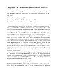
3.3 Buffered Direct Injection (BDI)Buffered direct injection 1181 is similar to direct injection except that inverting gain is provided between the detector andthe injection transistor gate, as shown in fig. 4. The gain can achieved, <strong>for</strong> example, by using a simple inverter circuit.The inverted gain provides feedback to yield better control over the detector bias at different photocurrent levels. As thephotocurrent increases, the input impedance of the injection transistor is decreased to maintain constant detector bias.The photoelectron charge-to-voltage conversion is still q/C measured in volts per electron. The cell now dissipatesactive power in the amplifier during integration. The injection efficiency (Ti) is improved compared to the direct injectioncase to:gmi(l Avo)Rol+gj(l+A0)R0where Avo is the low frequency gain of the inverting amplifier. Further, compared to a DI circuit with the same R0, Cjntand Cd, the cutoff frequency of the injection efficiency in BDI increases by (1+Ao), allowing much higher frequencyoperation of the unit cell.MUX BUSHC ṁtCdetVdet1VddFig. 4. Schematic of a buffered direct injectionunit cell circuit.Apart from an improvement in the injection efficiency, the inverting gain also helps to reduce the saturation frequencycompared with the DI circuit, thereby allowing longer integration times. The saturation frequency of a BDI circuit isgiven by: fsath/(2vmAvoPoCint), and is much smaller compared to the saturation frequency of DI and SFD. InBDI, improved injection efficiency, reduced saturation frequency and tighter bias control is achieved at the cost ofincreased power dissipation and added unit cell complexity. However, the inverting amplifier can be designed to operateat sufficiently low power, since it is required to drive only a small capacitance (approximately the gate capacitance of theinjection transistor).In spite of the increased injection efficiency achieved by BDI, it shares the same limitation with DI in terms of its use inultra low background applications, since the injection transistor has to operate at extremely low drain currents. The inputreferrednoise electrons of a BDI circuit (neglecting downstream noise and reset noise) is given by:270 / SPIE Vol. 2020 <strong>Infrared</strong> Technology XIX (1993)