P.13A-6 - LIL EVO
P.13A-6 - LIL EVO
P.13A-6 - LIL EVO

Create successful ePaper yourself
Turn your PDF publications into a flip-book with our unique Google optimized e-Paper software.
13A-1GROUP 13AMULTIPORT FUELINJECTION (MFI)CONTENTSGENERAL DESCRIPTION. . . . . . . . . 13A-3MULTIPORT FUEL INJECTION (MFI)DIAGNOSIS . . . . . . . . . . . . . . . . . . . . 13A-6TROUBLESHOOTING STRATEGY . . . . . . 13A-6DIAGNOSTIC FUNCTION . . . . . . . . . . . . . 13A-6FAIL-SAFE FUNCTION REFERENCETABLE. . . . . . . . . . . . . . . . . . . . . . . . . . . . . 13A-24DIAGNOSTIC TROUBLE CODE CHART. . 13A-25SYMPTOM CHART. . . . . . . . . . . . . . . . . . . 13A-27DIAGNOSTIC TROUBLE CODEPROCEDURES. . . . . . . . . . . . . . . . . . . . . . 13A-30SYMPTOM PROCEDURES . . . . . . . . . . . . 13A-551DATA LIST REFERENCE TABLE . . . . . . . 13A-723ACTUATOR TEST REFERENCE TABLE. . 13A-732CHECK AT THE ENGINE CONTROLMODULE (ECM) . . . . . . . . . . . . . . . . . . . . . 13A-734INSPECTION PROCEDURE USING ANOSCILLOSCOPE . . . . . . . . . . . . . . . . . . . . 13A-739SPECIAL TOOLS. . . . . . . . . . . . . . . . 13A-751ON-VEHICLE SERVICE. . . . . . . . . . . 13A-753COMPONENT LOCATION . . . . . . . . . . . . . 13A-753THROTTLE BODY (THROTTLE VALVE AREA)CLEANING . . . . . . . . . . . . . . . . . . . . . . . . . 13A-758THROTTLE POSITION SENSORADJUSTMENT . . . . . . . . . . . . . . . . . . . . . . 13A-758BASIC IDLE SPEED ADJUSTMENT . . . . . 13A-760FUEL PRESSURE TEST . . . . . . . . . . . . . . 13A-762FUEL PUMP CONNECTOR DISCONNECTION(HOW TO REDUCE PRESSURIZEDFUEL LINES) . . . . . . . . . . . . . . . . . . . . . . . 13A-765FUEL PUMP OPERATION CHECK . . . . . . 13A-766MULTIPORT FUEL INJECTION (MFI) RELAYCONTINUITY CHECK . . . . . . . . . . . . . . . . . 13A-767FUEL PUMP RELAY CONTINUITYCHECK . . . . . . . . . . . . . . . . . . . . . . . . . . . . 13A-768FUEL PUMP RESISTOR CHECK . . . . . . . . 13A-769INTAKE AIR TEMPERATURE SENSORCHECK . . . . . . . . . . . . . . . . . . . . . . . . . . . . 13A-769ENGINE COOLANT TEMPERATURE SENSORCHECK . . . . . . . . . . . . . . . . . . . . . . . . . . . . 13A-769THROTTLE POSITION SENSOR CHECK . 13A-770HEATED OXYGEN SENSOR CHECK . . . . 13A-771CLUTCH PEDAL POSITION SWITCHCHECK . . . . . . . . . . . . . . . . . . . . . . . . . . . . 13A-773INJECTOR CHECK . . . . . . . . . . . . . . . . . . . 13A-773INJECTOR RESISTOR CHECK . . . . . . . . . 13A-774IDLE AIR CONTROL MOTOR (STEPPER MOTOR)CHECK . . . . . . . . . . . . . . . . . . . . . . . . . . . . 13A-774FUEL PRESSURE SOLENOID CHECK . . . 13A-776EVAPORATIVE EMISSION PURGE SOLENOIDCHECK . . . . . . . . . . . . . . . . . . . . . . . . . . . . 13A-776EGR VACUUM REGULATOR SOLENOID VALVECHECK . . . . . . . . . . . . . . . . . . . . . . . . . . . . 13A-776EVAPORATIVE EMISSION VENTILATIONSOLENOID CHECK . . . . . . . . . . . . . . . . . . 13A-776TURBOCHARGER WASTEGATE SOLENOIDCHECK . . . . . . . . . . . . . . . . . . . . . . . . . . . . 13A-776INJECTOR . . . . . . . . . . . . . . . . . . . . . 13A-777REMOVAL AND INSTALLATION . . . . . . . . 13A-777THROTTLE BODY ASSEMBLY . . . . . 13A-779REMOVAL AND INSTALLATION . . . . . . . . 13A-779DISASSEMBLY AND ASSEMBLY . . . . . . . 13A-780Continued on next page
13A-2ENGINE CONTROL RESISTOR, RELAY 13A-782ENGINE CONTROL RESISTOR, RELAY REMOVALAND INSTALLATION . . . . . . . . . . . . . . . . . 13A-782ENGINE CONTROL MODULE (ECM) 13A-783ENGINE CONTROL MODULE (ECM) REMOVAL ANDINSTALLATION. . . . . . . . . . . . . . . . . . . . . . 13A-783SPECIFICATIONS . . . . . . . . . . . . . . . 13A-783FASTENER TIGHTENINGSPECIFICATIONS. . . . . . . . . . . . . . . . . . . . 13A-783GENERAL SPECIFICATIONS . . . . . . . . . . 13A-784SERVICE SPECIFICATIONS . . . . . . . . . . . 13A-784SEALANT AND ADHESIVE . . . . . . . . . . . . 13A-785
.The Multiport Fuel Injection System consists of sensors,actuators and the engine control module(ECM). The sensors detect the engine condition. Themodule controls the system based on signals fromthese sensors. The actuators work under the controlof the ECM. The ECM carries out activities such asfuel injection control, idle air control, and ignition timingcontrol. In addition, the ECM is equipped withseveral diagnostic test modes which simplify troubleshootingwhen a problem develops..FUEL INJECTION CONTROLThe ECM controls injection drive times and injectortiming to supply the optimum air/fuel mixture to theengine according to the continually-changing engineoperation conditions. A single injector is mounted atthe intake port of each cylinder. The fuel pump suppliespressurized fuel from the fuel tank to the fuelinjectors. The fuel pressure regulator controls thefuel pressure. Thus, the regulated fuel is distributedto each injector. Fuel is normally injected for eachcylinder every two rotations of the crankshaft. The firingorder is 1-3-4-2. Each cylinder has a dedicatedfuel injector. This is called "multiport". The ECM providesa richer air/fuel mixture by carrying out "openloop"control when the engine is cold or runningunder high load conditions. Thus, engine performanceis maintained. In addition, when the engine isunder normal operating temperature after warmingup,the ECM controls the air/fuel mixture according tothe heated oxygen sensor signal. This control is a"closed-loop" control. The closed-loop controlachieves the theoretical air/fuel mixture ratio wherethe catalytic converter can obtain the maximumcleaning performance..IDLE AIR CONTROLThe engine control module controls the amount of airthat bypasses the throttle valve according tochanges in idling conditions and engine load duringidling. Thus, idle speed is kept at an optimum speed.The ECM drives the idle air control (IAC) motoraccording to engine coolant temperature, A/C, andother electrical load. Thus, idle speed is kept at anoptimum speed. In addition, when the A/C switch isturned off and on while the engine is idling, the IACmotor adjusts the throttle valve bypass air amount.Thus, idle speed is maintained at constant speedregardless of various engine load conditions..MULTIPORT FUEL INJECTION (MFI)13A-3GENERAL DESCRIPTIONGENERAL DESCRIPTIONTSB RevisionM1131000100615IGNITION TIMING CONTROLThe ignition power transistor located in the ignitionprimary circuit turns on and off to control primary currentflow to the ignition coil. This maintains ignitiontiming at an optimum level regardless of variousengine operating conditions. The ECM determinesthe ignition timing according to engine speed, intakeair volume, engine coolant temperature, and atmosphericpressure..DIAGNOSTIC TEST MODE• When a fault is detected in any of the sensors oractuators related to emission control, the MalfunctionIndicator Lamp (SERVICE ENGINESOON) illuminates to warn the driver.• When a fault is detected in one of the sensors oractuators, a diagnostic trouble code correspondingto the fault is stored in the ECM.• The RAM data inside the ECM that is related tothe sensors and actuators can be read with thescan tool. In addition, the actuators can be controlledby the scan tool MB991502 (MUT-II) orMB991958 (MUT-III sub assembly) under certaincircumstances..OTHER CONTROL FUNCTIONSFuel Pump Control• Turns the fuel pump relay ON so that current issupplied to the fuel pump while the engine iscranking or running.A/C Compressor Clutch Relay Control• Turns the compressor clutch of the A/C ON andOFF.Fan Motor Control• The radiator fan and condenser fan speeds arecontrolled in response to the engine coolant temperatureand vehicle speed.Fuel Pressure Control• Supplies current to fuel pressure solenoid coil toraise the fuel pressure so that the fuel does notvaporize when the engine is started while it iswarm.Intake Charge Pressure Control• Control the intake charge pressure by controllingthe duty of the turbocharger wastegate solenoid.Generator Output Current Control• Prevents generator output current from increasingsuddenly and idle speed from dropping attimes such as when the headlights are turned on.
13A-4MULTIPORT FUEL INJECTION (MFI)GENERAL DESCRIPTIONEvaporative Emission Purge Control• (Refer to GROUP 17, Emission Control System −Evaporative Emission System − General InformationP.17-12.)EGR Control• (Refer to GROUP 17, Emission Control System −Exhaust Gas Recirculation (EGR) System − GeneralInformation P.17-16.)TSB Revision
MULTIPORT FUEL INJECTION (MFI)13A-5GENERAL DESCRIPTIONMULTIPORT FUEL INJECTION (MFI) SYSTEM DIAGRAMSENSE DECIDE ACT1 HEATED OXYGEN SENSOR (FRONT)2 VOLUME AIRFLOW SENSOR3 INTAKE AIR TEMPERATURE SENSOR4 THROTTLE POSITION SENSOR5 CAMSHAFT POSITION SENSOR6 CRANKSHAFT POSITION SENSOR7 BAROMETRIC PRESSURE SENSOR8 ENGINE COOLANT TEMPERATURE SENSOR9 KNOCK SENSOR10 HEATED OXYGEN SENSOR (REAR)11 MANIFOLD DIFFERENTIAL PRESSURE SENSOR12 FUEL TANK DIFFERENTIAL PRESSURE SENSOR13 FUEL TEMPERATURE SENSOR14 FUEL LEVEL SENSORPOWER SUPPLYVEHICLE SPEED SENSORA/C SWITCHPOWER STEERING PRESSURE SWITCHCLUTCH SWITCHIGNITION SWITCH - ST ECM1 INJECTOR2 EVAPORATIVE EMISSION PURGE SOLENOID3 IDLE AIR CONTROL MOTOR4 EGR SOLENOID5 EVAPORATIVE EMISSION VENTILATION SOLENOID6 FUEL PRESSURE SOLENOID7 TURBO CHARGER WASTEGATESOLENOIDFUEL PUMP RELAY 1, 2, 3MULTIPORT FUEL INJECTION(MFI) RELAYA/C COMPRESSER CLUTCH RELAYMALFUNCTION INDICATOR LAMP (SERVICE ENGINE SOON) DIAGNOSTIC OUTPUTIGNITION COIL, IGNITION POWER TRANSISTERFUEL TANK DIFFERENTIAL PRESSURE SENSOR12FUEL13TEMPERATURE2SENSOREVAPORATIVE 14 FUEL EMISSIONLEVELPURGE SENSORSOLENOID5 EVAPORATIVE EMISSIONVENTILATION SOLENOID FUEL TANKEVAPORATIVEEMISSIONCANISTER INTAKE AIR TEMPERATURESENSOR3BY-PASSVALVECHECKVALVE6FUELPRESSURESOLENOIDFUELPRESSUREREGULATORTOFUELTANK4 THROTTLEPOSITIONSENSOR3 IDLE AIR CONTROL MOTOR5 CAMSHAFTPOSITIONFROMSENSOR FUELPUMPINJECTOR1EGRVALVEMANIFOLDDIFFERENTIALPRESSURESENSOR114 EGR SOLENOIDAIR INLET2, 7VOLUME AIRFLOW SENSOR(WITH BAROMETRICPRESSURE SENSOR)7 TURBO CHARGERWASTEGATESOLENOIDTURBO CHARGERWASTEGATEACTUATOR1HEATED OXYGENSENSOR (FRONT)NOTE: For the vacuum hose routing, refer to GROUP 17, Vacuum Hoses P.17-8.8 ENGINE COOLANTTEMPERATURESENSOR6 CRANKSHAFT POSITION SENSOR9 KNOCK SENSOR10HEATED OXYGENSENSOR (REAR)AK200202ABTSB Revision
13A-6MULTIPORT FUEL INJECTION (MFI)MULTIPORT FUEL INJECTION (MFI) DIAGNOSISMULTIPORT FUEL INJECTION (MFI) DIAGNOSISTROUBLESHOOTING STRATEGYM1131150000308Use these steps to plan your diagnostic strategy. Ifyou follow them carefully, you will be sure to haveexhausted most of the possible ways to find an MFIfault.1. Gather as much information as possible about thecomplaint from the customer.2. Verify that the condition described by thecustomer exists.3. Check the vehicle for any MFI Diagnostic TroubleCode (DTC).4. If you cannot verify the condition and there are noDTCs, the malfunction is intermittent. Forinformation on how to cope with intermittentmalfunctions, refer to GROUP 00, How to UseTroubleshooting/Inspection Service Points − Howto cope with Intermittent Malfunction P.00-6.5. If you can verify the condition but there are noDTCs, or the system cannot communicate withthe scan tool, refer to the trouble symptomclassification table.6. If there is a DTC, record the number of the code,then erase the code from the memory using thescan tool.NOTE: If a DTC is erased, its "freeze frame" data willbe also erased and the system readiness test statuswill be reset. If necessary, store the "freeze frame"data before erasing the DTC.7. Reconfirm the malfunction symptom and carry outa test drive with the drive cycle pattern.8. If DTC is set again, carry out an inspection withappropriate diagnostic trouble code procedures.9. If DTC is not set again, the malfunction isintermittent. For information on how to cope withintermittent malfunctions, refer to GROUP 00,How to Use Troubleshooting/Inspection ServicePoints − How to cope with Intermittent MalfunctionP.00-6.10.After repairs are completed, conduct a road testduplicating the complaint set conditions to confirmthe malfunction has been corrected.DIAGNOSTIC FUNCTIONM1131155500029MALFUNCTION INDICATOR LAMP(SERVICE ENGINE SOON) AK202418AB.MALFUNCTION INDICATOR LAMP (SERVICE ENGINESOON)Among the on-board diagnostic items, a Malfunction IndicatorLamp (SERVICE ENGINE SOON) illuminates to notify thedriver of an emission control malfunction.However, when an irregular signal returns to normal and theengine control module (ECM) judges that it has returned to normal,the Malfunction Indicator Lamp (SERVICE ENGINESOON) is switched off.Moreover, when the ignition switch is turned off, the lamp isswitched off. Even if the ignition switch is turned on again, thelamp does not illuminate until the malfunction is detected.Immediately after the ignition switch is turned on, the MalfunctionIndicator Lamp (SERVICE ENGINE SOON) is lit for 20seconds to indicate that the Malfunction Indicator Lamp (SER-VICE ENGINE SOON) operates normally..TSB Revision
MULTIPORT FUEL INJECTION (MFI)MULTIPORT FUEL INJECTION (MFI) DIAGNOSIS13A-7Items Indicated by the Malfunction Indicator Lamp (SERVICE ENGINE SOON)DTC NO. ITEMS−Engine control module (ECM) malfunctionP0090 Fuel pressure solenoid circuitP0101* Volume airflow circuit range/performance problemP0102* Volume airflow circuit low inputP0106* Barometric pressure circuit range/performance problemP0107* Barometric pressure circuit low inputP0108* Barometric pressure circuit high inputP0111* Intake air temperature circuit range/performance problemP0112* Intake air temperature circuit low inputP0113* Intake air temperature circuit high inputP0116* Engine coolant temperature circuit range/performance problemP0117* Engine coolant temperature circuit low inputP0118* Engine coolant temperature circuit high inputP0121* Throttle position sensor circuit range/performance problemP0122* Throttle position sensor circuit low inputP0123* Throttle position sensor circuit high inputP0125* Insufficient coolant temperature for closed loop fuel controlP0128 Coolant thermostat (Coolant temperature below thermostat regulating temperature)P0130 Heated oxygen sensor circuit (sensor 1)P0131 Heated oxygen sensor circuit low voltage (sensor 1)P0132 Heated oxygen sensor circuit high voltage (sensor 1)P0133 Heated oxygen sensor circuit slow response (sensor 1)P0134* Heated oxygen sensor circuit no activity detected (sensor 1)P0135 Heated oxygen sensor heater circuit (sensor 1)P0136 Heated oxygen sensor circuit (sensor 2)P0137 Heated oxygen sensor circuit low voltage (sensor 2)P0138 Heated oxygen sensor circuit high voltage (sensor 2)P0139 Heated oxygen sensor circuit slow response (sensor 2)P0141 Heated oxygen sensor heater circuit (sensor 2)P0171 System too leanP0172 System too richP0181 Fuel tank temperature sensor circuit range/performanceP0182 Fuel tank temperature sensor circuit low inputP0183 Fuel tank temperature sensor circuit high inputP0201 Injector circuit-cylinder 1P0202 Injector circuit-cylinder 2P0203 Injector circuit-cylinder 3P0204 Injector circuit-cylinder 4P0234 Turbocharger wastegate system malfunctionTSB Revision
13A-8MULTIPORT FUEL INJECTION (MFI)MULTIPORT FUEL INJECTION (MFI) DIAGNOSISDTC NO.ITEMSP0243 Turbocharger wastegate solenoid circuitP0300 Random/multiple cylinder misfire detectedP0301 Cylinder 1 misfire detectedP0302 Cylinder 2 misfire detectedP0303 Cylinder 3 misfire detectedP0304 Cylinder 4 misfire detectedP0325 Knock sensor circuitP0335* Crankshaft position sensor circuitP0340* Camshaft position sensor circuitP0401 Exhaust gas recirculation flow insufficient detectedP0403 Exhaust gas recirculation control circuitP0421 Warm up catalyst efficiency below thresholdP0441 Evaporative emission system incorrect purge flowP0442 Evaporative emission system leak detected (Small leak)P0443 Evaporative emission system purge control valve circuitP0446 Evaporative emission system vent control circuitP0451 Evaporative emission system pressure sensor range/performanceP0452 Evaporative emission system pressure sensor low inputP0453 Evaporative emission system pressure sensor high inputP0455 Evaporative emission system leak detected (Gross leak)P0456 Evaporative emission system leak detected (Very small leak)P0461 Fuel level sensor circuit range/performance (sensor 1)P0500 Vehicle speed sensorP0506 Idle control system RPM lower than expectedP0507 Idle control system RPM higher than expectedP0551 Power steering pressure sensor circuit range/performanceP0554 Power steering pressure sensor circuit intermittentP1400 Manifold differential pressure sensor circuit malfunctionP1603* Battery backup circuit malfunctionP2066 Fuel level sensor circuit range/performance (sensor 2)NOTE: If the Malfunction Indicator Lamp (SERVICE ENGINE SOON) illuminates because of a malfunction ofthe engine control module (ECM), communication between the scan tool and the ECM is impossible. In thiscase, the diagnostic trouble code (DTC) cannot be read.NOTE: After the ECM has detected a malfunction, the Malfunction Indicator Lamp (SERVICE ENGINESOON) illuminates when the engine is next turned on and the same malfunction is re-detected. However, foritems marked with a "*" in the DTC NO column, the Malfunction Indicator Lamp (SERVICE ENGINE SOON)illuminates on the first detection of the malfunction.NOTE: After the Malfunction Indicator Lamp (SERVICE ENGINE SOON) illuminates, it will be switched offunder the following conditions..• When the ECM monitored the power train malfunction three times* it met set condition requirements, itdetected no malfunction. *: In this case, "one time" indicates from engine start to stop.TSB Revision
MULTIPORT FUEL INJECTION (MFI)13A-9MULTIPORT FUEL INJECTION (MFI) DIAGNOSIS• For misfiring or a fuel trim malfunction, when driving conditions (engine speed, engine coolant temperature,etc.) are similar to those when the malfunction was first recorded.NOTE: Sensor 1 indicates the sensor mounted at a position closest to the engine, and sensor 2 indicates thesensor mounted at the position second closest to the engine.HOW TO CONNECT THE SCAN TOOL (MUT-lll)16-PINMB991824MB991827MB991911AK204071ABRequired Special Tools:• MB991958: Scan Tool (MUT-lll Sub Assembly)• MB991824: V.C.I• MB991827: USB Cable• MB991911: Main Harness BCAUTIONTo prevent damage to scan tool MB991958, always turn theignition switch to the "LOCK" (OFF) position before connectingor disconnecting scan tool MB991958.1. Ensure that the ignition switch is at the "LOCK" (OFF)position.2. Start up the personal computer.3. Connect special tool MB991827 to special tool MB991824and the personal computer.4. Connect special tool MB991911 to special tool MB991824.5. Connect special tool MB991911 to the data link connector.6. Turn the power switch of special tool MB991824 to the "ON"position.NOTE: When the special tool MB991824 is energized, specialtool MB991824 indicator light will be illuminated in agreen color.7. Start the MUT-Ill system on the personal computer.NOTE: Disconnecting the scan tool MB991958 is thereverse of the connecting sequence, making sure that theignition switch is at the "LOCK" (OFF) position.16-PINHOW TO READ AND ERASE DIAGNOSTICTROUBLE CODE.Required Special Tool:• MB991502: Scan Tool (MUT-II)CAUTIONTo prevent damage to scan tool MB991502, always turn theignition switch to the "LOCK" (OFF) position before connectingor disconnecting scan tool MB991502.NOTE: If Battery positive voltage is low, diagnostic troublecodes may not be output. Be sure to check the battery andcharging system before continuing.MB991502AK204070ABTSB Revision
13A-10MULTIPORT FUEL INJECTION (MFI)MULTIPORT FUEL INJECTION (MFI) DIAGNOSISNOTE: If battery cable is disconnected or if the engine controlmodule (ECM) connector is disconnected, the diagnostic troublecodes will be erased. Do not disconnect the battery cable orECM connector until the diagnostic trouble codes have beenrecorded.NOTE: If a DTC is erased, its "freeze frame" data will be alsoerased and the system readiness test status will be reset. Ifnecessary, store the "freeze frame" data before erasing theDTC.1. Connect scan tool MB991502 to the data link connector.2. Turn the ignition switch to the "ON" position.3. Read the diagnostic trouble codes for MFI.4. Refer to the DIAGNOSTIC TROUBLE CODECHART(<strong>P.13A</strong>-25).5. Turn the ignition switch to the "LOCK" (OFF) position andthen back to "ON" again.6. Erase the diagnostic trouble code(s) using MB991502screen prompts.7. Confirm that the diagnostic trouble code output is normal.8. Turn the ignition switch to the "LOCK" (OFF) position.9. Disconnect scan tool MB991502 from the data linkconnector.16-PINMB991824MB991911.Required Special Tools:• MB991958: Scan Tool (MUT-lll Sub Assembly)• MB991824: V.C.I• MB991827: USB Cable• MB991911: Main Harness BCAUTIONTo prevent damage to scan tool MB991958, always turn theignition switch to the "LOCK" (OFF) position before connectingor disconnecting scan tool MB991958.NOTE: If the battery voltage is low, diagnostic trouble codes willnot be set. Check the battery if scan tool MB991958 does notdisplay.1. Connect scan tool MB991958 to the data link connector.2. Turn the ignition switch to the "ON" position.3. Select "Interactive Diagnosis" from the start-up screen.4. Select "System select."5. Choose "MFI" from the "POWER TRAIN" tab.6. Select "MITSUBISHI."7. Select "Diagnostic Trouble Code"8. If a DTC is set, it is shown.9. Choose "Erase DTCs" to erase the DTC.MB991827AK204071ABTSB Revision
MODE 6 REFERENCE TABLEThe engine control module (ECM) monitors the conditionof emission control system.TESTIDMONITORINGITEM01 CatalystmonitorMULTIPORT FUEL INJECTION (MFI)13A-11MULTIPORT FUEL INJECTION (MFI) DIAGNOSISSIMPLE TECHNICALDESCRIPTIONECM monitors the deterioration ofcatalyst by the output frequencyratio between heated oxygensensor (front) and heated oxygensensor (rear).03 EGR monitor ECM monitors the operation ofEGR system by the pressuredifference of intake manifoldbetween before and afterintroduction of EGR using themanifold differential pressuresensor.06 Evaporationleak monitor(Small leak)07 Evaporationleak monitor(Gross leak)After PCM vacuumizes the fueltank and the fuel line and then thespecified time is passed, PCMmonitors the leak of fuelevaporation gas through the fueltank differential pressure sensorto check the reduction of vacuumin the fuel tank.ECM monitors the leak of fuelevaporation gas by checkingwhether the pressure can bereduced (the amount of pressurereduction) using the fuel tankdifferential pressure sensor aftersealing the fuel tank and the fuelline.TSB RevisionPROVISIONAL DTCs [SCAN TOOL MB991502 orMB991958 OBD-II Test Mode − Results (Mode 7)]The scan tool will display the Provisional DTCs reported byengine control module (ECM) if the ECM detects some malfunctionfor "Misfire", "Fuel System" and "Comprehensive"monitoring during a SINGLE Driving Cycle. The intended use ofthis data is to assist the technician after a vehicle repair, andafter clearing diagnostic information, by reporting test resultafter a SINGLE Driving Cycle. Note that the test resultsreported by this mode do not necessarily indicate a faulty component/system.If test results indicate a failure after ADDI-TIONAL (consecutive) driving, then the Malfunction IndicatorLamp (SERVICE ENGINE SOON) will be illuminated and aDTC will set.By selecting MODE 6 using scan tool, Test Resultand Limit Value (minimum) *1 or (maximum) *2 aboutthe main items of emission control system whichECM monitors can be confirmed. The value at thelast monitoring is output by ECM as a test result.INDICATION OF SCANTOOLCatalyst Frequency RatioTest Result and LimitValue (max.)EGR Monitor PressureValue Test Result andLimit Value (min.) kPaEVAP Leak Mon. 1 mmPressure Value TestResult and Limit Value(max.) kPaEVAP Leak Mon. GrossPressure Value TestResult and Limit Value(min.) kPaCONVERSIONCOEFFICIENT INUSING GENERALSCAN TOOL× 0.0039× 0.43 kPa× 0.032 kPa× 0.032 kPa
13A-12MULTIPORT FUEL INJECTION (MFI)MULTIPORT FUEL INJECTION (MFI) DIAGNOSISTESTIDMONITORINGITEMSIMPLE TECHNICALDESCRIPTIONINDICATION OF SCANTOOLCONVERSIONCOEFFICIENT INUSING GENERALSCAN TOOL08 Evaporationleak monitor(Very smallleak)After PCM vacuumizes the fueltank and the fuel line and then thespecified time is passed, PCMmonitors the leak of fuelevaporation gas through the fueltank differential pressure sensorto check the reduction of vacuumin the fuel tank.EVAP Leak Mon. 0.5 mmPressure Value TestResult and Limit Value(max.) kPa× 0.032 kPa09 Heated oxygensensor (front)monitor (Rich/LeanSwitching)ECM monitors the deterioratedcondition of the heated oxygensensor (front) by checking thelean/rich switching frequency ofthe heated oxygen sensor (front).HO2S B1 SENSOR1Rich/Lean SwitchingCount Test Result andLimit Value (min.)× 1 count0BHeated oxygensensor (rear)monitor(VoltageChange)The engine control unit checksthe output voltage of the heatedoxygen sensor (rear) in order tomonitor whether the heatedoxygen sensor (rear) output isstuck.HO2S B1 SENSOR2Change in Volt Test Resultand Limit Value (min.)× 19.5 mVNOTE: *1: Minimum value: The test fails if test value is less than this value.NOTE: *2: Maximum value: The test fails if test value is greater than this value.DIAGNOSTIC BY DIAGNOSTIC TEST MODE II(INCREASED SENSITIVITY)Required Special Tools:• MB991502: Scan Tool (MUT-II)• MB991958: Scan Tool (MUT-III Sub Assembly)• MB991824: V.C.I.• MB991827: USB Cable• MB991911: Main Harness BTSB Revision
MULTIPORT FUEL INJECTION (MFI)13A-13MULTIPORT FUEL INJECTION (MFI) DIAGNOSIS16-PIN16-PINMB991824MB991827MB991502AK204070ABMB991911AK204071ABCAUTIONTo prevent damage to scan tool MB991502 or MB991958,always turn the ignition switch to the "LOCK" (OFF) positionbefore connecting or disconnecting scan toolMB991502 or MB991958.NOTE: When mode II is selected with scan tool MB991502(MUT-II) or MB991958 (MUT-III sub assembly), the MalfunctionIndicator Lamp (SERVICE ENGINE SOON) will light when theengine control module (ECM) first detects the trouble (Note thatthis is only for emission-related trouble). At the same time, therelevant diagnostic trouble codes will be registered. In respectto the comprehensive component electrical faults (opens/shorts), the time for the diagnostic trouble code to be registeredafter the fault occurrence is four seconds → one second.Therefore, the confirmation of the trouble symptom and theconfirmation after completing repairs can be reduced. To returnto the normal mode I after mode II has been selected once, theignition switch must be turned "OFF" once or mode I must bereselected with scan tool MB991502 (MUT-II) or MB991958(MUT-III sub assembly). The diagnostic trouble code, systemreadiness test status and freeze frame data, etc., will be erasedwhen mode I is returned to, so record these before returning tomode 1.1. Connect scan tool MB991502 or MB991958 to the data linkconnector.2. Turn the ignition switch to the "ON" position.3. Change the diagnostic test mode of the ECM toDIAGNOSTIC TEST MODE II (INCREASED SENSITIVITY).4. Road test the vehicle.5. Read the diagnostic trouble code and repair themalfunctioning part.6. Turn the ignition switch to the "LOCK" (OFF) position.7. Disconnect scan tool MB991502 or MB991958 from the datalink connector.INSPECTION USING SCAN TOOL MB991502 orMB991958, DATA LIST AND ACTUATOR TESTING.Required Special Tool:• MB991502: Scan Tool (MUT-II)TSB Revision
13A-14MULTIPORT FUEL INJECTION (MFI)MULTIPORT FUEL INJECTION (MFI) DIAGNOSIS16-PINMB991502AK204070ABCAUTIONTo prevent damage to scan tool MB991502, always turn theignition switch to the "LOCK" (OFF) position before connectingor disconnecting scan tool MB991502.1. Connect scan tool MB991502 to the data link connector.2. Turn the ignition switch to the "ON" position.3. Carry out inspection by means of the data list and theactuator test function. If there is an abnormality, check andrepair the chassis harnesses and components. Refer toData List Reference Table (<strong>P.13A</strong>-723).Refer to Actuator Test Reference Table (<strong>P.13A</strong>-732).4. Re-check using scan tool MB991502 and check to be surethat the abnormal input and output have returned to normalbecause of the repairs.5. Erase the diagnostic trouble code(s).6. Turn the ignition switch to the "LOCK" (OFF) position.7. Disconnect scan tool MB991502 from the data linkconnector.8. Start the engine again and do a test drive to confirm that theproblem is eliminated.16-PINMB991824MB991911.Required Special Tools:• MB991958: Scan Tool (MUT-lll Sub Assembly)• MB991824: V.C.I.• MB991827: USB Cable• MB991911: Main Harness BCAUTIONTo prevent damage to scan tool MB991958, always turn theignition switch to the "LOCK" (OFF) position before connectingor disconnecting scan tool MB991958.1. Connect scan tool MB991958 to the data link connector.2. Turn the ignition switch to the "ON" position.3. Select "Interactive Diagnosis" from the start-up screen.4. Select "System select."5. Choose "MFI" from the "POWER TRAIN" tab.6. Select "MITSUBISHI."7. Select "Data List" or "Actuator Test."8. Choose an appropriate item and select the "OK" button.MB991827AK204071ABTSB Revision
MULTIPORT FUEL INJECTION (MFI)13A-15MULTIPORT FUEL INJECTION (MFI) DIAGNOSISON-BOARD DIAGNOSTICSThe engine control module (ECM) monitors the input/output signals (some signals all the time and othersunder specified conditions) of the ECM. When a malfunction continues for a specified time or longer after theirregular signal is initially monitored, the ECM judges that a malfunction has occurred. After the ECM firstdetects a malfunction, a diagnostic trouble code is recorded when the engine is restarted and the same malfunctionis re-detected. However, for items marked with a "*", a diagnostic trouble code is recorded on the firstdetection of the malfunction. There are 71 diagnostic items. The diagnostic results can be read out with ascan tool. Since memorization of the diagnostic trouble codes is backed up directly by the battery, the diagnosticresults are memorized even if the ignition key is turned off. The diagnostic trouble codes will, however,be erased when the battery terminal or the ECM connector is disconnected. In addition, the diagnostic troublecode can also be erased by turning the ignition switch to ON and sending the diagnostic trouble code erasesignal from scan tool to the ECM.NOTE: If the sensor connector is disconnected with the ignition switch turned on, the diagnostic trouble codeis memorized. In this case, send the diagnostic trouble code erase signal to the ECM in order to erase thediagnostic memory. The 71 diagnostic items are all indicated sequentially from the smallest code number.The ECM records the engine operating condition when the diagnostic trouble code is set. This data is called"Freeze-frame" data. This data can be read by using the scan tool, and can then be used in simulation testsfor troubleshooting. Data items are as follows:NOTE: If the ECM detects multiple malfunctions, the ECM stores the data for only the first item that wasdetected.However, if the ECM detects a misfire or a fuel system malfunction, the ECM stores the data by giving priorityto the misfire or fuel system malfunction, regardless of the order in which the malfunction was detected.NOTE: As for Diagnostic trouble code P1603, "freeze frame" data is not memorized.SCAN TOOL DISPLAY ITEM DATA ITEMUNIT or STATENO.ECT SENSOR 21 Engine coolant temperature sensor °C or °FENGINE LOAD 87 Calculated load value %ENGINE SPEED 22 Crankshaft position sensor r/minIAT SENSOR 13 Intake air temperature sensor °C or °FIG. TIMING ADV 44 Ignition coils and ignition power degtransistorLONG TRIM B1 81 Long-term fuel trim %SHORT TRIM B1 82 Short-term fuel trim %SYS. STATUS B1 88 Fuel system status • Open loop• Closed loop• Open loop-drivecondition• Open loop-DTC set• Closed loop-O 2 (rear)failedTP SENSOR 8A Throttle position sensor %VAF SENSOR 12 Volume airflow sensor (mass airflow gm/srate)VSS 24 Vehicle speed sensor km/h or mphTSB Revision
13A-16MULTIPORT FUEL INJECTION (MFI)MULTIPORT FUEL INJECTION (MFI) DIAGNOSISOBD- II DRIVE CYCLEAll kinds of diagnostic trouble codes (DTCs) can be monitored by carrying out a short drive according to thefollowing six drive cycle pattern. In other words, doing such a drive regenerates any kind of trouble whichinvolves illuminating the Malfunction Indicator Lamp (SERVICE ENGINE SOON) and verifies the repair procedurehas eliminated the trouble (the Malfunction Indicator Lamp (SERVICE ENGINE SOON) is no longerilluminated).CAUTIONTwo technicians should always be in the vehicle when carrying out a test drive.NOTE: Check that the diagnosis trouble code (DTC) is not output before driving the OBD-II drive cycle. Erasethe DTC if it has been output.DRIVE CYCLE PATTERN LISTPROCEDURE MONITOR ITEM DIAGNOSTIC TROUBLECODE (DTC)1 Evaporative emission system leak monitor P0441, P0442, P0451,P0452, P0453, P0455,P04562 Fuel trim monitor P0171,P01723 Catalytic converter monitor P04214 Heated oxygen sensor monitor P0133, P01395 Exhaust gas recirculation (EGR) system monitor P04016 Other monitor Main components P0134, P0300, P0301,P0302, P0303, P0304,P0506, P0507, P1400Sensors and switches P0101, P0102, P0106,P0107, P0108, P0111,P0112, P0113, P0116,P0117, P0118, P0121,P0122, P0123, P0125,P0181, P0182, P0183,P0335, P0340, P0461,P2066Wire breakage and shortcircuitP0090, P0130, P0131,P0132, P0135, P0136,P0137, P0138, P0141,P0201, P0202, P0203,P0204, P0243, P0403,P0443, P0446.TSB Revision
MULTIPORT FUEL INJECTION (MFI)13A-17MULTIPORT FUEL INJECTION (MFI) DIAGNOSISPROCEDURE 1EVAPORATIVE EMISSION SYSTEM LEAK MONITORDTC P0441, P0442, P0451, P0452, P0453, P0455, P0456Drive cyclepatternThis monitor [from start to ignition switch to the "LOCK" (OFF) position] will be completed while driving the vehiclewith the following drive cycle pattern. It will take 8 minutes. You must complete this drive twice.NOTE: Vehicle speed and throttle opening angle should be within the shaded range.97(60)200 SECONDSOR MORE150 SECONDSOR MORE89 - 97 km/h (55 - 60 mph)M/T: 5TH SPEEDVEHICLE SPEEDkm/h (mph)64(40)32(20)(2)(3)PREPARATIONPERIOD(4)DURINGMONITOR(5)0(1)100ENGINE STARTIGNITION SWITCH:"LOCK" (OFF) positionCALCULATEDLOAD (%)500AKX01345ACInspectionconditions• Engine coolant temperature: 45°C (113°F) or less (The engine is stopped before the test drive is started)• Atmospheric temperature: 5 − 45°C (41 − 113°F)TSB Revision
13A-18MULTIPORT FUEL INJECTION (MFI)MULTIPORT FUEL INJECTION (MFI) DIAGNOSISEVAPORATIVE EMISSION SYSTEM LEAK MONITORTest procedure1. Engine: start2. Accelerate until the vehicle speed is 89 − 97 km/h (55 − 60 mph).3. Travel for 200 seconds or more while keeping the vehicle speed at 89 − 97 km/h (55 − 60 mph). (M/T: 5th speed)4. While keeping the accelerator pedal opening degree constant, keep the vehicle speed at 89 − 97 km/h (55 − 60 mph) andtravel for 150 seconds or more. (During monitor)5. Return the vehicle to the shop, then turn the ignition switch to "LOCK" (OFF) position.6. Confirm that the diagnostic trouble code (DTC) is not output.7. If DTC P0441 is output, refer to GROUP 13A, DTC P0441 − Evaporative Emission System Incorrect Purge Flow <strong>P.13A</strong>-358.If DTC P0442 is output, refer to GROUP 13A, DTC P0442 − Evaporative Emission System Leak Detected (Small Leak)<strong>P.13A</strong>-345.If DTC P0451 is output, refer to GROUP 13A, DTC P0451 − Evaporative Emission System Pressure Sensor Range/performance <strong>P.13A</strong>-380.If DTC P0452 is output, refer to GROUP 13A, DTC P0452 − Evaporative Emission System Pressure Sensor Low Input<strong>P.13A</strong>-397.If DTC P0453 is output, refer to GROUP 13A, DTC P0453 − Evaporative Emission System Pressure Sensor High Input<strong>P.13A</strong>-414.If DTC P0455 is output, refer to GROUP 13A, DTC P0455 − Evaporative Emission System Leak Detected (Gross Leak)<strong>P.13A</strong>-431.If DTC P0456 is output, refer to GROUP 13A, DTC P0456 − Evaporative Emission System Leak Detected (Very SmallLeak) <strong>P.13A</strong>-447..TSB Revision
MULTIPORT FUEL INJECTION (MFI)13A-19MULTIPORT FUEL INJECTION (MFI) DIAGNOSISPROCEDURE 2FUEL TRIM MONITORDTC P0171, P0172Drive cyclepatternThis monitor [from start to ignition switch to the "LOCK" (OFF) position] will be completedwhile driving the vehicle with the following drive cycle pattern. It will take 35 minutes. Youmust complete this drive twice.NOTE: Vehicle speed and throttle opening angle should be within the shaded range.30 MINUTES OR MORE89 - 97 km/h (55 - 60 mph)M/T: 5TH SPEED97(60)(3)VEHICLE SPEEDkm/h (mph)64(40)32(20)(2)WITH 120 SECONDSDURING MONITOR(4)0(1)ENGINE START100IGNITION SW-ITCH: "LOCK"(OFF) positionCALCULATEDLOAD (%)500AKX01346 ACInspectionconditionsTestprocedure• Engine coolant temperature: 80 − 97°C (176 − 207°F)• Atmospheric temperature: −10 − 60°C (14 − 140°F)1. Engine: start2. Accelerate until the vehicle speed is 89 − 97 km/h (55 − 60 mph).3. Travel for 30 minutes or more while keeping the vehicle speed at 89 − 97 km/h (55 − 60mph). (M/T: 5th speed) Carry out one gradual deceleration/acceleration returning to 89 −97 km/h (55 − 60 mph) within 120 seconds. (During monitor)4. Return the vehicle to the shop, then turn the ignition switch to "LOCK" (OFF) position.5. Confirm that the diagnostic trouble code (DTC) is not output.If DTC P0171 is output, refer to GROUP 13A, DTC P0171 − System too lean <strong>P.13A</strong>-232..If DTC P0172 is output, refer to GROUP 13A, DTC P0172 − System too rich <strong>P.13A</strong>-240..TSB Revision
13A-20MULTIPORT FUEL INJECTION (MFI)MULTIPORT FUEL INJECTION (MFI) DIAGNOSISPROCEDURE 3CATALYTIC CONVERTER MONITORDTC P0421Drive cyclepatternThis monitor [from start to ignition switch to the "LOCK" (OFF) position] will be completed while drivingthe vehicle with the following drive cycle pattern. It will take 20 minutes. You must complete this drivetwice.NOTE: Vehicle speed and throttle opening angle should be within the shaded range.300 SECONDS OR MORE72 - 97 km/h (45 - 60 mph)M/T: 5TH SPEED97(60)(3)90 SECONDS OR MORE56 - 64 km/h (35 - 40 mph)M/T: 4TH SPEEDVEHICLESPEEDkm/h (mph)64(40)32(20)0(1)(2)PREPARATIONPERIOD(4)(5) (5)1 STMON-ITOR(5) (5)(6) (6) (6)2 NDMON-ITOR6 THMON-ITOR(7)100CALCULATEDLOAD (%)50ENGINESTARTIGNITIONSWITCH:"LOCK"(OFF) position0FULLDECEL-ERATIONFULLDECEL-ERATIONFULLDECEL-ERATIONAKX01347ACInspectionconditionsTest procedure• Atmospheric temperature: −10°C (14°F) or more• A/C switch: OFF1. Engine: start2. Accelerate until the vehicle speed is 72 km/h (45 mph).3. Travel for 300 seconds or more while keeping the vehicle speed at 72 − 97 km/h (45 − 60 mph). (M/T: 5th speed)4. Decelerate until the vehicle speed is within 56 − 64 km/h (35 − 40 mph).5. While keeping the accelerator pedal opening degree constant (M/T: 4th speed), keep the vehiclespeed at 56 − 64 km/h (35 − 40 mph) and travel for 90 seconds or more. (During monitor)6. Fully close the throttle and decelerate, and keep the deceleration state for 10 seconds. Then,quickly accelerate until the vehicle speed reaches 56 − 64 km/h (35 − 40 mph). Then, repeat steps5 and 6, and complete six monitor sessions.7. Return the vehicle to the shop, then turn the ignition switch to "LOCK" (OFF) position.8. Confirm that the diagnostic trouble code (DTC) is not output.9. If DTC P0421 is output, refer to GROUP 13A, DTC P0421 − Warm Up Catalyst Efficiency BelowThreshold (Bank 1) <strong>P.13A</strong>-337..TSB Revision
MULTIPORT FUEL INJECTION (MFI)13A-21MULTIPORT FUEL INJECTION (MFI) DIAGNOSISPROCEDURE 4HEATED OXYGEN SENSOR MONITORDTC P0133, P0139Drive cyclepatternThis monitor [from start to ignition switch to the "LOCK" (OFF) position] will be completedwhile driving the vehicle with the following drive cycle pattern. It will take 5 minutes. You mustcomplete this drive twice.NOTE: Vehicle speed and throttle opening angle should be within the shaded range.97(60)120 SECONDS OR MORE56 - 64 km/h (35 - 40 mph)M/T: 4TH SPEED64(40)(3)VEHICLE SPEEDkm/h (mph)32(20)(2)DURING MONITOR(4)0(1)100ENGINESTARTIGNITIONSWITCH: "LOCK"(OFF) positionCALCULATEDLOAD (%)500AKX01348 ACInspectionconditionsTestprocedure• Engine coolant temperature: 80°C (176°F) or more• Atmospheric temperature: −10°C (14°F) or more1. Engine: start2. Accelerate until the vehicle speed is 56 − 64 km/h (35 − 40 mph).3. While keeping the accelerator pedal opening degree constant (M/T: 4th speed), keep thevehicle speed at 56 − 64 km/h (35 − 40 mph) and travel for 120 seconds or more. (Duringmonitor)4. Return the vehicle to the shop, then turn the ignition switch to "LOCK" (OFF) position.5. Confirm that the diagnostic trouble code (DTC) is not output.6. If DTC P0133 is output, refer to GROUP 13A, DTC P0133 − Heated oxygen SensorCircuit Slow Response (Sensor 1) <strong>P.13A</strong>-180.If DTC P0139 is output, refer to GROUP 13A, DTC P0139 − Heated oxygen SensorCircuit Slow Response (Sensor 2) <strong>P.13A</strong>-220..TSB Revision
13A-22MULTIPORT FUEL INJECTION (MFI)MULTIPORT FUEL INJECTION (MFI) DIAGNOSISPROCEDURE 5EXHAUST GAS RECIRCULATION (EGR) SYSTEM MONITORDTC P0401Drive cyclepatternThis monitor [from start to ignition switch to the "LOCK" (OFF) position] will be completedwhile driving the vehicle with the following drive cycle pattern. It will take 10 minutes. Youmust complete this drive twice.NOTE: Vehicle speed and throttle opening angle should be within the shaded range.20 SECONDS OR MORE56 - 64 km/h (35 - 40 mph)M/T: 4TH SPEED20 SECONDS OR MOREVEHICLESPEEDkm/h (mph)64(40)32(20)0(1)(2)(3) (5) (5) (5) (5)(4) (4) (4) (4) (4)1 STMON-ITOR2 NDMON-ITOR7 THMON-ITOR8 THMON-ITOR100ENGINE STARTIGNITIONSWITCH:"LOCK"(OFF) positionCALCULATEDLOAD (%) 500FULL FULLDECEL- DECEL-ERATION ERATIONFULLDECEL-ERATIONFULL FULLDECEL- DECEL-ERATION ERATIONAKX01349ACInspectionconditionsTest procedure• Engine coolant temperature: 80°C (176°F) or more• Atmospheric temperature: 5°C (41°F) or more• A/C switch: OFF1. Engine: start2. Accelerate until the vehicle speed is 56 − 64 km/h (35 − 40 mph).3. Travel for 20 seconds or more while keeping the vehicle speed at 56 − 64 km/h (35 − 40 mph). (M/T: 4th speed)4. Fully close the throttle from an engine speed of 2,000 − 3,000 r/min, and while keeping the clutchengaged, decelerate to approximately 900 r/min without applying the brakes. Do not steer thehandle or turn the light ON/OFF during this time. (During monitor)5. Accelerate until the vehicle speed reaches 56 − 64 km/h (35 − 40 mph), and travel for 20 secondsor more (M/T: 4th speed). Then, repeat steps 4 and 5 and complete 8 monitor sessions.6. Return the vehicle to the shop, then turn the ignition switch to "LOCK" (OFF) position.7. Confirm that the diagnostic trouble code (DTC) is not output.8. If DTC P0401 is output, refer to GROUP 13A, DTC P0401 − Exhaust Gas Recirculation FlowInsufficient detected <strong>P.13A</strong>-328.TSB Revision
MULTIPORT FUEL INJECTION (MFI)13A-23MULTIPORT FUEL INJECTION (MFI) DIAGNOSIS.PROCEDURE 6OTHER MONITOR (Main components, sensors and switches, wire breakage and short circuit)DTC • Main components: P0134, P0300, P0301, P0302, P0303, P0304, P0506, P0507, P1400• Sensors and switches: P0101, P0102, P0106, P0107, P0108, P0111, P0112, P0113, P0116, P0117, P0118,P0121, P0122, P0123, P0125, P0181, P0182, P0183, P0335, P0340, P0461, P2066• Wire breakage and short circuit: P0090, P0130, P0131, P0132, P0135, P0136, P0137, P0138, P0141, P0201,P0202, P0203, P0204, P0243, P0403, P0443, P0446Drive cyclepatternThis monitor [from start to ignition switch to the "LOCK" (OFF) position] will be completed while drivingthe vehicle with the following drive cycle pattern. It will take 10 minutes. You must complete this drivetwice.NOTE: Drive according to the graph below.300 SECONDS OR MORE56 - 64 km/h (35 - 40 mph)M/T: 4TH SPEED64(40)(3)VEHICLESPEEDkm/h (mph)32(20)(2)(4)ENGINE: IDLINGTRANSMISSION: NEUTRAL300 SECONDS0(1)100ENGINE STARTIGNITIONSWITCH:"LOCK"(OFF) positionCALCULATEDLOAD (%)500AKX01350 ACInspectionconditionsTest procedure• Engine coolant temperature: 80°C (176°F) or more• Atmospheric temperature: 5°C (41°F) or more1. Engine: start2. Accelerate until the vehicle speed is 56 − 64 km/h (35 − 40 mph), and travel for 300 seconds or more. (M/T:4th speed)3. Return the vehicle to the shop.4. After stopping the vehicle, continue idling for 300 seconds, and then turn the ignition switch to the "LOCK"(OFF) position. Moreover, the vehicle should be set to the following conditions for idling.• A/C switch: OFF• Lights and all accessories: OFF• Transmission: Neutral• Steering wheel: Straightforward position5. Confirm that the diagnostic trouble code (DTC) is not output.6. If a DTC is displayed, refer to Diagnostic Trouble Code Chart <strong>P.13A</strong>-25.TSB Revision
13A-24SYSTEM READINESS TEST STATUS.PURPOSEThe Readiness function (also referred to as I/MReadiness or I/M Flags) indicates if a full diagnosticcheck has been "Completed" (is "Ready") for eachnon-continuous monitor. Enhanced I/M State EmissionPrograms will use the Readiness status (Codes)to see if the vehicle is ready for OBD-II testing."Incomplete" (Not Ready) codes will be one of thetriggers for I/M failure..OVERVIEWThe engine control module (ECM) monitors the followingmain diagnosis items and records whether theevaluation was completed or is incomplete. TheReadiness codes were established for the I/M programs,thereby confirming that the vehicle was nottampered with by erasing the diagnostic troublecode(s) (DTC's) before I/M testing. The Readinessand DTC codes can be reset by disconnecting thebattery or by erasing the codes with a scan tool. Forthis reason all Readiness codes must read "Complete"before I/M testing.FAIL-SAFE FUNCTION REFERENCE TABLEMULTIPORT FUEL INJECTION (MFI)MULTIPORT FUEL INJECTION (MFI) DIAGNOSISTSB RevisionWhen the monitors run and complete, the scan toolwill record the Readiness Code as "Complete" (GeneralScan Tools record as "Ready"). If the monitor didnot run completely, the system then reads as "Incomplete"(General Scan Tools record as "Not Ready").When the vehicle is operating normally and the OBD-II Drive Cycle is carried out, Readiness Code will setas "Complete" on the first drive cycle. If during thefirst drive cycle a fault is detected then, a seconddrive is required before the Readiness Code will"Complete." If the fault is still there, then a DTC willset.• Catalyst: P0421• Evaporative system: P0442, P0455, P0456• Heated oxygen sensor: P0133• Heated oxygen sensor heater: P0135, P0141• EGR system: P0401After the Readiness is "Complete," the technician isassured that any DTC's associated with that monitorwill be displayed if the system has a problem. That iswhy some State's I/M programs require the ReadinessCode as "Complete" before they check forDTC's.NOTE: After a repair is mode for a DTC the technicianshould drive the OBD-II drive cycle checkingthat the MB991502 or MB991958 records all Readinessas "Complete".M1131153000181When the main sensor malfunctions are detected by the diagnostic test mode, the vehicle is controlled bymeans of the following defaults.MALFUNCTION ITEMVolume airflow sensorIntake air temperaturesensorThrottle position sensorEngine coolanttemperature sensorCONTROL CONTENTS DURING MALFUNCTION• Uses the throttle position sensor signal and engine speed signal (crankshaftposition sensor signal) for basic injector drive time and basic ignition timingfrom the pre-set mapping.• Fixes the IAC motor in the appointed position so idle air control is notperformed.Controls as if the intake air temperature is 25°C (77°F).No increase in fuel injection amount during acceleration due to the unreliablethrottle position sensor signal.Controls as if the engine coolant temperature is 80°C (176°F). (This control willbe continued until the ignition switch is turned to the "LOCK" (OFF) positioneven though the sensor signal returns to normal.)Camshaft position sensor Injects fuel into the cylinders in the order 1-3-4-2 with irregular timing. (After theignition switch is turned to the "ON," the No.1 cylinder top dead center is notdetected at all.)Barometric pressure Controls as if the barometric pressure is 101 kPa (30 in Hg).sensorKnock sensorSwitches the ignition timing from ignition timing for high octane to ignition timingfor standard octane fuel.
MULTIPORT FUEL INJECTION (MFI)13A-25MULTIPORT FUEL INJECTION (MFI) DIAGNOSISMALFUNCTION ITEMHeated oxygen sensorHeated oxygen sensorGenerator FR terminalMisfire detectionCONTROL CONTENTS DURING MALFUNCTIONAir/fuel ratio closed loop control is not performed.Performs the closed loop control of the air/fuel ratio by using only the signal ofthe heated oxygen sensor (front) installed on the front side of the catalyticconverter.Does not restrict the generator output with respect to electrical load (to beoperated as an ordinary generator).The ECM stops supplying fuel to the cylinder with the highest misfiring rate if amisfiring that could damage the catalytic converter is detected.DIAGNOSTIC TROUBLE CODE CHARTTSB RevisionM1131151000453DTC DIAGNOSTIC ITEMS REFERENCEPAGEP0090 Fuel pressure solenoid circuit <strong>P.13A</strong>-30P0101* Volume airflow circuit range/performance problem <strong>P.13A</strong>-38P0102* Volume airflow circuit low input <strong>P.13A</strong>-45P0106* Barometric pressure circuit range/performance problem <strong>P.13A</strong>-53P0107* Barometric pressure circuit low input <strong>P.13A</strong>-59P0108* Barometric pressure circuit high input <strong>P.13A</strong>-73P0111* Intake air temperature circuit range/performance problem <strong>P.13A</strong>-83P0112* Intake air temperature circuit low input <strong>P.13A</strong>-90P0113* Intake air temperature circuit high input <strong>P.13A</strong>-94P0116* Engine coolant temperature circuit range/performance problem <strong>P.13A</strong>-101P0117* Engine coolant temperature circuit low input <strong>P.13A</strong>-111P0118* Engine coolant temperature circuit high input <strong>P.13A</strong>-115P0121* Throttle position sensor circuit range/performance problem <strong>P.13A</strong>-123P0122* Throttle position sensor circuit low input <strong>P.13A</strong>-132P0123* Throttle position sensor circuit high input <strong>P.13A</strong>-140P0125* Insufficient coolant temperature for closed loop fuel control <strong>P.13A</strong>-147P0128 Coolant thermostat (coolant temperature below thermostat regulating <strong>P.13A</strong>-155temperature)P0130 Heated oxygen sensor circuit (sensor 1) <strong>P.13A</strong>-156P0131 Heated oxygen sensor circuit low voltage (sensor 1) <strong>P.13A</strong>-170P0132 Heated oxygen sensor circuit high voltage (sensor 1) <strong>P.13A</strong>-176P0133 Heated oxygen sensor circuit slow response (sensor 1) <strong>P.13A</strong>-180P0134* Heated oxygen sensor circuit no activity detected (sensor 1) <strong>P.13A</strong>-185P0135 Heated oxygen sensor heater circuit (sensor 1) <strong>P.13A</strong>-192P0136 Heated oxygen sensor circuit (sensor 2) <strong>P.13A</strong>-201P0137 Heated oxygen sensor circuit low voltage (sensor 2) <strong>P.13A</strong>-211P0138 Heated oxygen sensor circuit high voltage (sensor 2) <strong>P.13A</strong>-216
13A-26MULTIPORT FUEL INJECTION (MFI)MULTIPORT FUEL INJECTION (MFI) DIAGNOSISDTC DIAGNOSTIC ITEMS REFERENCEPAGEP0139 Heated oxygen sensor circuit slow response (sensor 2) <strong>P.13A</strong>-220P0141 Heated oxygen sensor heater circuit (sensor 2) <strong>P.13A</strong>-224P0171 System too lean <strong>P.13A</strong>-232P0172 System too rich <strong>P.13A</strong>-240P0181 Fuel tank temperature sensor circuit range/performance <strong>P.13A</strong>-246P0182 Fuel tank temperature sensor circuit low input <strong>P.13A</strong>-254P0183 Fuel tank temperature sensor circuit high input <strong>P.13A</strong>-259P0201 Injector circuit-Cylinder 1 <strong>P.13A</strong>-267P0202 Injector circuit-Cylinder 2 <strong>P.13A</strong>-267P0203 Injector circuit-Cylinder 3 <strong>P.13A</strong>-267P0204 Injector circuit-Cylinder 4 <strong>P.13A</strong>-267P0234 Turbocharger wastegate system malfunction <strong>P.13A</strong>-277P0243 Turbocharger wastegate solenoid circuit <strong>P.13A</strong>-279P0300 Random/multiple cylinder misfire detected <strong>P.13A</strong>-286P0301 Cylinder 1 misfire detected <strong>P.13A</strong>-292P0302 Cylinder 2 misfire detected <strong>P.13A</strong>-292P0303 Cylinder 3 misfire detected <strong>P.13A</strong>-292P0304 Cylinder 4 misfire detected <strong>P.13A</strong>-292P0325 Knock sensor circuit <strong>P.13A</strong>-296P0335* Crankshaft position sensor circuit <strong>P.13A</strong>-302P0340* Camshaft position sensor circuit <strong>P.13A</strong>-317P0401 Exhaust gas recirculation flow insufficient detected <strong>P.13A</strong>-328P0403 Exhaust gas recirculation control circuit <strong>P.13A</strong>-330P0421 Warm up catalyst efficiency below threshold <strong>P.13A</strong>-337P0441 Evaporative emission system incorrect purge flow <strong>P.13A</strong>-358P0442 Evaporative emission system leak detected (Small leak) <strong>P.13A</strong>-345P0443 Evaporative emission system purge control valve circuit <strong>P.13A</strong>-363P0446 Evaporative emission system vent control circuit <strong>P.13A</strong>-371P0451 Evaporative emission system pressure sensor range/performance <strong>P.13A</strong>-380P0452 Evaporative emission system pressure sensor low input <strong>P.13A</strong>-397P0453 Evaporative emission system pressure sensor high input <strong>P.13A</strong>-414P0455 Evaporative emission system leak detected (Gross leak) <strong>P.13A</strong>-431P0456 Evaporative emission system leak detected (Very small leak) <strong>P.13A</strong>-447P0461 Fuel level sensor circuit range/performance (sensor 1) <strong>P.13A</strong>-459P0500 Vehicle speed sensor <strong>P.13A</strong>-465P0506 Idle control system RPM lower than expected <strong>P.13A</strong>-477TSB Revision
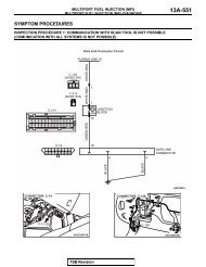
MULTIPORT FUEL INJECTION (MFI)13A-27MULTIPORT FUEL INJECTION (MFI) DIAGNOSISDTC DIAGNOSTIC ITEMS REFERENCEPAGEP0507 Idle control system RPM higher than expected <strong>P.13A</strong>-487P0513 Immobilizer malfunction <strong>P.13A</strong>-496P0551 Power steering pressure sensor circuit range/performance <strong>P.13A</strong>-500P0554 Power steering pressure sensor circuit intermittent <strong>P.13A</strong>-510P0622 Generator FR terminal circuit malfunction <strong>P.13A</strong>-516P0830 Clutch pedal position switch circuit range/performance <strong>P.13A</strong>-523P1400 Manifold differential pressure sensor circuit malfunction <strong>P.13A</strong>-530P1603* Battery backup circuit malfunction <strong>P.13A</strong>-538P2066 Fuel level sensor circuit range/performance (sensor 2) <strong>P.13A</strong>-523P2263Intake charge system malfunctionNOTE: Do not replace the engine control module (ECM) until a through terminal check reveals there are noshort/open circuits.NOTE: Check that the ECM ground circuit is normal before checking for the cause of the problem.NOTE: After the ECM detects a malfunction, a diagnostic trouble code is recorded the next time the engine isstarted and the same malfunction is re-detected. However, for items marked with a "*," the diagnostic troublecode is recorded on the first detection of the malfunction.NOTE: Sensor 1 indicates the sensor mounted at a position closest to the engine, and sensor 2 indicates thesensor mounted at the position second closest to the engine.SYMPTOM CHARTM1131151500447.NOTE: Check that the engine control module (ECM) ground circuit is normal before checking for the cause ofthe problem.SYMPTOMSCommunicationwith scan tool isimpossibleMalfunctionIndicator Lamp(SERVICEENGINESOON) andrelated partsINSPECTIONPROCEDUREREFERENCEPAGECommunication with all systems is not possible 1 <strong>P.13A</strong>-551Communication with ECM only is not possible 2 <strong>P.13A</strong>-554The malfunction indicator lamp (SERVICE ENGINESOON) does not illuminate right after the ignitionswitch is turned to the "ON" positionThe malfunction indicator lamp (SERVICE ENGINESOON) remains illuminated and never goes out3 <strong>P.13A</strong>-5574 <strong>P.13A</strong>-562Starting Cranks, won't start 5 <strong>P.13A</strong>-565Starts up and dies 6 <strong>P.13A</strong>-570Hard starting 7 <strong>P.13A</strong>-577Idling stability(improperidling)Unstable idle (rough idle, hunting) 8 <strong>P.13A</strong>-582Idle speed is high (improper idle speed) 9 <strong>P.13A</strong>-590Idle speed is low (improper idle speed) 10 <strong>P.13A</strong>-593TSB Revision
13A-28MULTIPORT FUEL INJECTION (MFI)MULTIPORT FUEL INJECTION (MFI) DIAGNOSISSYMPTOMSINSPECTIONPROCEDUREREFERENCEPAGEIdling stability When the engine is cold, it stalls at idle (die out) 11 <strong>P.13A</strong>-596(engine stalls)When the engine is hot, it stalls at idle (die out) 12 <strong>P.13A</strong>-601The engine stalls when accelerating (pass out) 13 <strong>P.13A</strong>-608The engine stalls when decelerating 14 <strong>P.13A</strong>-610Driving Hesitation, sag or stumble 15 <strong>P.13A</strong>-614Acceleration shock 16 <strong>P.13A</strong>-620Deceleration shock 17 <strong>P.13A</strong>-621Poor acceleration 18 <strong>P.13A</strong>-623Surge 19 <strong>P.13A</strong>-629Knocking 20 <strong>P.13A</strong>-635Dieseling (Run-on) 21 <strong>P.13A</strong>-637Too high CO and HC concentration when idling 22 <strong>P.13A</strong>-637IM240 test Transient, mass emission tailpipe test failure 23 <strong>P.13A</strong>-641failurePurge flow test of the evaporative emission canister 24 <strong>P.13A</strong>-648failurePressure test of the evaporative system failure 25 <strong>P.13A</strong>-649Generator output voltage is low (approximately 12.3 volts) 26 <strong>P.13A</strong>-651Improper idle speed when the A/C is on (A/C switch 2 signal) 27 <strong>P.13A</strong>-655Radiator fan is inoperative 28 <strong>P.13A</strong>-657A/C condensor fan is inoperative 29 <strong>P.13A</strong>-660Power supply system and ignition switch-IG system 30 <strong>P.13A</strong>-663Fuel pump system 31 <strong>P.13A</strong>-671Ignition switch − ST system 32 <strong>P.13A</strong>-688Ignition circuit system 33 <strong>P.13A</strong>-695A/C system 34 <strong>P.13A</strong>-703Charge air cooler water spray system 35 <strong>P.13A</strong>-706Charge air cooler water spray lamp system 36 <strong>P.13A</strong>-718.PROBLEM SYMPTOMS TABLE (FOR YOUR INFORMATION)ITEMSSYMPTOMStarting Won't start The starter is used to crank the engine, but there is no combustionwithin the cylinders, and the engine won't start.Starts up and The engine starts, but then the engine soon stalls.diesHard starting Engine starts after cranking a while.TSB Revision
ITEMSMULTIPORT FUEL INJECTION (MFI)13A-29MULTIPORT FUEL INJECTION (MFI) DIAGNOSISIdling stability Hunting Engine speed doesn't remain constant; changes at idle.Rough idle Usually, a judgement can be based upon the movement of thetachometer pointer, and the vibration transmitted to the steering wheel,shift lever, body, etc.Incorrect idlespeedThe engine doesn't idle at the correct speed.Engine stall (dieout)Engine stall(pass out)SYMPTOMThe engine stalls when the foot is taken from the accelerator pedal,regardless of whether the vehicle is moving or not.The engine stalls when the accelerator pedal is depressed.Driving Hesitation Sag " Hesitation " is the delay inresponse of the vehicle speed(engine speed). This occurs whenthe accelerator is depressed inorder to accelerate from the speedat which the vehicle is nowtraveling, or a temporary drop invehicle speed (engine speed)during such acceleration.Serious hesitation is called "sag".VEHICLESPEEDINITIALACCELE-RATORPEDALDEPRE-SSIONHESITATIONNORMALTIMESAGAKX01361ABPooraccelerationStumblePoor acceleration is inability to obtain an acceleration corresponding tothe degree of throttle opening, even though acceleration is smooth orthe inability to reach maximum speed.Engine speed increase is delayedwhen the accelerator pedal isinitially depressed for acceleration.VEHICLESPEEDStoppingShockSurgeKnockingDieseling (runon)INITIALACCEL- NORMALERATORPEDALDEP-RESSIONIDLINGTIMESTUMBLEAKX01362The feeling of a comparatively large impact or vibration when theengine is accelerated or decelerated.This is slight acceleration and deceleration feel usually felt duringsteady, light throttle cruise. Most notable under light loads.A sharp sound during driving, which sounds like a hammer striking thecylinder walls. It makes poor driveability.The condition in which the engine continues to run after the ignitionswitch is turned to the "LOCK" (OFF) position. Also called " dieseling. "TSB Revision
13A-30MULTIPORT FUEL INJECTION (MFI)MULTIPORT FUEL INJECTION (MFI) DIAGNOSISDIAGNOSTIC TROUBLE CODE PROCEDURESDTC P0090: FUEL PRESSURE SOLENOID CIRCUITFuel Pressure Solenoid CircuitBATTERYBLACK-YELLOWB-12XBLACK-YELLOWBLACK-YELLOW1 21 23 4OFFONMFIRELAY43B-28(MU802722)1 2RED-YELLOW1FUEL PRESSURE SOLENOID2C-121(MU801824)WHITE-BLACK31 2 3 4 5 6 7 8 9 10 11 12 1314 15 16 17 18 19 20 21 22 23 24 25 26ENGINE CONTROLMODULE (ECM)AK203463CONNECTOR: B-28FUEL PRESSURESOLENOIDCONNECTOR: C-121ECMB-28 (B)C-121 (Y)AK203486ABAK203487ABTSB Revision
MULTIPORT FUEL INJECTION (MFI)13A-31MULTIPORT FUEL INJECTION (MFI) DIAGNOSISCONNECTOR: B-12XMFI RELAYAK203489AB.CIRCUIT OPERATION• The fuel pressure solenoid power is suppliedfrom the MFI relay (terminal No. 4).• The ECM controls the fuel pressure solenoidground by turning the power transistor in theECM "ON" and "OFF"..TECHNICAL DESCRIPTION• To judge if there is open circuit in the fuel pressuresolenoid drive circuit, ECM measures thesurge voltage of the fuel pressure solenoid coil.• The ECM drives the fuel pressure solenoid. Afterthe solenoid is turned off, the ECM will check ifthe solenoid coil produces a surge voltage of 2volts or more..DTC SET CONDITIONSCheck Conditions• Engine is being cranked.• Battery positive voltage is at between 10 and 16volts.DIAGNOSISJudgment Criteria• The fuel pressure solenoid coil surge voltage(battery positive voltage + 2 volts) is not detectedfor 0.2 second.• The ECM monitors for this condition once duringthe drive cycle.Check Conditions• Battery positive voltage is at between 10 and 16volts.• Fuel pressure solenoid is ON.• Turbocharger wastegate solenoid is OFF.• More than 1 second has elapsed after the abovementioned conditions have been met.Judgment Criteria• The fuel pressure solenoid coil surge voltage(battery positive voltage + 2 volts) is not detectedfor 1 second. When the fuel pressure solenoid isturned OFF..TROUBLESHOOTING HINTS (The most likelycauses for this code to be set are:)• Fuel pressure solenoid failed.• Open or shorted fuel pressure solenoid circuit,harness damage, or connector damage.• ECM failed.Required Special Tools:• MB991502: Scan Tool (MUT-II)• MB991958: Scan Tool (MUT-III Sub Assembly)• MB991824: V.C.I.• MB991827: USB Cable• MB991911: Main Harness BTSB Revision
13A-32MULTIPORT FUEL INJECTION (MFI)MULTIPORT FUEL INJECTION (MFI) DIAGNOSIS16-PIN16-PINMB991502AK204070ABSTEP 1. Using scan tool MB991502 or MB991958, checkactuator test item 13: fuel pressure solenoid.CAUTIONTo prevent damage to scan tool MB991502 or MB991958,always turn the ignition switch to the "LOCK" (OFF) positionbefore connecting or disconnecting scan toolMB991502 or MB991958.(1) Connect scan tool MB991502 or MB991958 to the data linkconnector.(2) Turn the ignition switch to the "ON" position.(3) Set scan tool MB991502 or MB991958 to the actuator testmode for item 12, fuel pressure solenoid.• An operation sound should be heard and vibrationshould be felt when the fuel pressure solenoid is operated.(4) Turn the ignition switch to the "LOCK" (OFF) position.Q: Is the solenoid operating properly?YES : It can be assumed that this malfunction is intermittent.Refer to GROUP 00, How to Use Troubleshooting/Inspection Service Points P.00-6.NO : Go to Step 2.MB991911MB991824MB991827AK204071ABCONNECTOR: B-28HARNESS 2 1CONNECTOR:COMPONENT SIDESTEP 2. Check harness connector B-28 at the fuelpressure solenoid for damage.Q: Is the harness connector in good condition?YES : Go to Step 3.NO : Repair or replace it. Refer to GROUP 00E, HarnessConnector Inspection P.00E-2. Then go to Step 12.B-28 (B)AK203490ABTSB Revision
MULTIPORT FUEL INJECTION (MFI)13A-33MULTIPORT FUEL INJECTION (MFI) DIAGNOSISCONNECTOR: B-28HARNESS 2 1CONNECTOR:COMPONENT SIDESTEP 3 Check the fuel pressure solenoid.(1) Disconnect the fuel pressure solenoid connector B-28.B-28 (B)AK203490ABFUEL PRESSURE SOLENOID CONNECTOR1 2(2) Measure the resistance between fuel pressure solenoidside connector terminal No. 1 and No. 2.Standard value: 29 − 35 ohms [at 20°C (68°F)]Q: Is the resistance between 29 and 35 ohms [at 20°C(68°F)]?YES : Go to Step 4.NO : Replace the fuel pressure solenoid. Then go to Step12.AK203491ABCONNECTOR: B-28HARNESS 2 1CONNECTOR:COMPONENT SIDESTEP 4. Measure the power supply voltage at fuel pressuresolenoid harness side connector B-28.(1) Disconnect connector B-28 and measure at the harnessside.(2) Turn the ignition switch to the "ON" position.B-28 (B)AK203490ABB-28 HARNESS CONNECTOR: COMPONENT SIDE21(3) Measure the voltage between terminal No. 1 and ground.• Voltage should measure battery positive voltage.(4) Turn the ignition switch to the "LOCK" (OFF) position.Q: Is battery positive voltage (approximately 12 volts)present?YES : Go to Step 6.NO : Go to Step 5.AK203492ABTSB Revision
13A-34MULTIPORT FUEL INJECTION (MFI)MULTIPORT FUEL INJECTION (MFI) DIAGNOSISCONNECTOR: B-12X2 14B-12X3HARNESSCONNECTOR:COMPONENT SIDEAK203493ABSTEP 5. Check harness connector B-12X at MFI relay fordamage.Q: Is the harness connector in good condition?YES : Repair harness wire between MFI relay connector B-12X (terminal No. 4) and fuel pressure solenoidconnector B-101 (terminal No. 1) because of opencircuit or short circuit to ground. Then go to Step 12.NO : Repair or replace it. Refer to GROUP 00E, HarnessConnector Inspection P.00E-2. Then go to Step 12.CONNECTOR: C-121STEP 6. Measure the power supply voltage at ECMconnector C-121 by backprobing.(1) Do not disconnect connector C-121.(2) Turn the ignition switch to the "ON" position.HARNESSCONNECTOR:COMPONENT SIDE13 12 11 10 9 8 7 6 5 4 3 2 126 25 24 23 22 21 20 19 18 17 16 15 14C-121 (Y)AK203488AB1 2 3 4 5 6 7 8 9 10 11 12 1314 15 16 17 18 19 20 21 22 23 24 25 26C-121 HARNESSCONNECTOR:HARNESS SIDEAK203494AB(3) Measure the voltage between terminal No. 3 and ground bybackprobing.• Voltage should measure battery positive voltage.(4) Turn the ignition switch to the "LOCK" (OFF) position.Q: Is battery positive voltage (approximately 12 volts)present?YES : Go to Step 9.NO : Go to Step 7.CONNECTOR: C-121STEP 7. Check harness connector C-121 at ECM fordamage.Q: Is the harness connector in good condition?YES : Go to Step 8.NO : Repair or replace it. Refer to GROUP 00E, HarnessConnector Inspection P.00E-2. Then go to Step 12.HARNESSCONNECTOR:COMPONENT SIDE13 12 11 10 9 8 7 6 5 4 3 2 126 25 24 23 22 21 20 19 18 17 16 15 14C-121 (Y)AK203488ABTSB Revision
MULTIPORT FUEL INJECTION (MFI)13A-35MULTIPORT FUEL INJECTION (MFI) DIAGNOSISCONNECTOR: B-28HARNESS 2 1CONNECTOR:COMPONENT SIDESTEP 8. Check for open circuit and short circuit to groundbetween fuel pressure solenoid connector B-28 (terminalNo. 2) and ECM connector C-121 (terminal No. 3).Q: Is the harness wire in good condition?YES : Replace the ECM. Then go to Step 12.NO : Repair it. Then go to Step 12.B-28 (B)AK203490ABCONNECTOR: C-121HARNESSCONNECTOR:COMPONENT SIDE13 12 11 10 9 8 7 6 5 4 3 2 126 25 24 23 22 21 20 19 18 17 16 15 14C-121 (Y)AK203488ABCONNECTOR: C-121STEP 9. Check harness connector C-121 at ECM fordamage.Q: Is the harness connector in good condition?YES : Go to Step 10.NO : Repair or replace it. Refer to GROUP 00E, HarnessConnector Inspection P.00E-2. Then go to Step 12.HARNESSCONNECTOR:COMPONENT SIDE13 12 11 10 9 8 7 6 5 4 3 2 126 25 24 23 22 21 20 19 18 17 16 15 14C-121 (Y)AK203488ABTSB Revision
13A-36MULTIPORT FUEL INJECTION (MFI)MULTIPORT FUEL INJECTION (MFI) DIAGNOSISCONNECTOR: B-12XB-12XSTEP 10. Check for harness damage between MFI relayconnector B-12X (terminal No. 4) and fuel pressuresolenoid connector B-28 (terminal No. 1).Q: Is the harness wire in good condition?YES : Go to Step 11.NO : Repair it. Then go to Step 12.2 143HARNESSCONNECTOR:COMPONENT SIDEAK203493ABCONNECTOR: B-28HARNESS 2 1CONNECTOR:COMPONENT SIDEB-28 (B)AK203490ABCONNECTOR: B-28HARNESS 2 1CONNECTOR:COMPONENT SIDESTEP 11. Check for harness damage between fuelpressure solenoid connector B-28 (terminal No. 2) andECM connector C-121 (terminal No. 3).Q: Is the harness wire in good condition?YES : Replace the ECM. Then go to Step 12.NO : Repair it. Then go to Step 12.B-28 (B)AK203490ABCONNECTOR: C-121HARNESSCONNECTOR:COMPONENT SIDE13 12 11 10 9 8 7 6 5 4 3 2 126 25 24 23 22 21 20 19 18 17 16 15 14C-121 (Y)AK203488ABTSB Revision
MULTIPORT FUEL INJECTION (MFI)13A-37MULTIPORT FUEL INJECTION (MFI) DIAGNOSISSTEP 12. Perform the OBD-II drive cycle.(1) Carry out a test drive with the drive cycle pattern. Refer toGROUP 13A, Diagnostic Function − OBD-II Drive Cycle −Procedure 6 − Other Monitor <strong>P.13A</strong>-6.(2) Check the diagnostic trouble code (DTC).Q: Is DTC P0090 set?YES : Repeat the troubleshooting.NO : The procedure is complete.TSB Revision
13A-38MULTIPORT FUEL INJECTION (MFI)MULTIPORT FUEL INJECTION (MFI) DIAGNOSISDTC P0101: VOLUME AIRFLOW CIRCUIT RANGE/PERFORMANCE PLOBLEMVolume Airflow Sensor CircuitBATTERYB-12X1 23 4BLACK-YELLOWOFFRED-YELLOW4BLACK-YELLOW BLACK-YELLOW1 2ON4 3MFIRELAYB-105(MU802552)1 2 3 4 5 6 7VOLUME AIRFLOWSENSOR75 3C-119(MU801822)BLUE-BLACKBLACKWHITE-RED31 32 33 34 35 36 37 3839 40 41 42 43 44 45 461940 90C-115(MU801823)C-121(MU801824)1 234 5 6 7 8 9 10 11 12 1314 15 16 17 18 19 20 21 22 23 24 25 265VENGINE CONTROLMODULE(ECM)71 72 73 74 75 76 77 78 79 80 8182 83 84 85 86 87 88 89 90 91 92AK203464TSB Revision
MULTIPORT FUEL INJECTION (MFI)13A-39MULTIPORT FUEL INJECTION (MFI) DIAGNOSISCONNECTOR: B-12XCONNECTOR: C-115, C-119, C-121MFI RELAYECMAK203489ABC-115(Y)C-119(Y)C-121(Y)AK203487ACCONNECTOR: B-105VOLUME AIRFLOW SENSORB-105 (B)AK203495AB.CIRCUIT OPERATION• The volume airflow sensor power is supplied fromthe MFI relay (terminal No. 4), and the ground isprovided on the ECM (terminal No. 40).• 5-volt power is applied to the volume airflow sensoroutput terminal (terminal No. 3) from the ECM(terminal No. 90). The volume airflow sensor generatesa pulse signal when the output terminaland ground are opened/closed (opened/short).• The volume airflow reset signal is input by theECM (terminal No. 19) to the volume airflow sensor(terminal No. 7)..TECHNICAL DESCRIPTION• While the engine is running, the volume airflowsensor outputs a pulse signal which correspondsto the volume of airflow.• The ECM checks whether the frequency of thissignal output by the volume airflow sensor whilethe engine is running is at or above the set value.• When the throttle position sensor output voltageis low, the ECM causes the power transistor to be"ON" to send an airflow sensor reset signal to theairflow sensor. In response to the reset signal, theairflow sensor resets the filter circuit andimproves the ability of the airflow sensor to measurethe amount of air in a small air intake region..DTC SET CONDITIONSCheck Conditions• Throttle position sensor output voltage is 1.5 voltsor higher.• Engine speed is higher than 2,000 r/min.Judgement Criteria• Volume airflow sensor output frequency has continuedto be 60 Hz or lower for 2 seconds.Check Conditions• Throttle position sensor output voltage is 2 voltsor lower.• Engine speed is lower than 2,000 r/min.Judgement Criteria• Volume airflow sensor output frequency has continuedto be 1,000 Hz or higher for 2 seconds..TROUBLESHOOTING HINTS (The most likelycauses for this code to be set are:)• Volume airflow sensor failed.• Open or shorted volume airflow sensor circuit,harness damage, or connector damage.• ECM failed.• Air leak between volume airflow sensor and throttlebody.TSB Revision
13A-40MULTIPORT FUEL INJECTION (MFI)MULTIPORT FUEL INJECTION (MFI) DIAGNOSIS16-PIN16-PINMB991502AK204070ABMB991911DIAGNOSISRequired Special Tools:• MB991502: Scan Tool (MUT-II)• MB991958: Scan Tool (MUT-III Sub Assembly)• MB991824: V.C.I.• MB991827: USB Cable• MB991911: Main Harness BSTEP 1. Using scan tool MB991502 or MB991958, checkdata list item 12: Volume Airflow Sensor.CAUTIONTo prevent damage to scan tool MB991502 or MB991958,always turn the ignition switch to the "LOCK" (OFF) positionbefore connecting or disconnecting scan toolMB991502 or MB991958.(1) Connect scan tool MB991502 or MB991958 to the data linkconnector.(2) Start the engine and run at idle.(3) Set scan tool MB991502 or MB991958 to the data readingmode for item 12, Volume Airflow Sensor.(4) Warm up the engine to normal operating temperature: 80°Cto 95°C (176°F to 203°F).• The standard value during idling should be 10 Hz ormore.• When the engine is revved, the frequency shouldincrease according to the increase in engine speed.(5) Turn the ignition switch to the "LOCK" (OFF) position.Q: Is the sensor operating properly?YES : It can be assumed that this malfunction is intermittent.Refer to GROUP 00, How to Use Troubleshooting/Inspection Service Points P.00-6.NO : Go to Step 2.MB991824MB991827AK204071ABTSB Revision
MULTIPORT FUEL INJECTION (MFI)13A-41MULTIPORT FUEL INJECTION (MFI) DIAGNOSISCONNECTOR: B-105STEP 2. Measure the reset signal voltage at volume airflowsensor connector B-105 by backprobing.(1) Do not disconnect connector B-105.(2) Turn the ignition switch to the "ON" position.B-105 (B)7 6 5 4 3 2 1HARNESS CONNECTOR:COMPONENT SIDEAK203496ABB-105 HARNESSCONNECTOR:HARNESS SIDE1 2 3 4 5 6 7(3) Measure the voltage between terminal No. 7 and ground bybackprobing.• Voltage should measure between 6.0 and 9.0 volts.(4) Turn the ignition switch to the "LOCK" (OFF) position.Q: Is the measured voltage between 6.0 and 9.0 volts?YES : Go to Step 5.NO : Go to Step 3.AKX01515AHCONNECTOR: B-105STEP 3. Check connector B-105 at volume airflow sensorand connector C-121 at ECM for damage.Q: Is the connector in good condition?YES : Go to Step 4.NO : Repair or replace it. Refer to GROUP 00E, HarnessConnector Inspection P.00E-2. Then go to Step 9.B-105 (B)7 6 5 4 3 2 1HARNESS CONNECTOR:COMPONENT SIDEAK203496ABCONNECTOR: C-121HARNESSCONNECTOR:COMPONENT SIDE13 12 11 10 9 8 7 6 5 4 3 2 126 25 24 23 22 21 20 19 18 17 16 15 14C-121 (Y)AK203488ABTSB Revision
13A-42MULTIPORT FUEL INJECTION (MFI)MULTIPORT FUEL INJECTION (MFI) DIAGNOSISCONNECTOR: B-105STEP 4. Check for short circuit to ground between volumeairflow sensor connector B-105 (terminal No. 7) and ECMconnector C-121 (terminal No. 19).Q: Is the harness wire in good condition?YES : Replace the volume airflow sensor. Then go to Step9.NO : Repair it. Then go to Step 9.B-105 (B)7 6 5 4 3 2 1HARNESS CONNECTOR:COMPONENT SIDEAK203496ABCONNECTOR: C-121HARNESSCONNECTOR:COMPONENT SIDE13 12 11 10 9 8 7 6 5 4 3 2 126 25 24 23 22 21 20 19 18 17 16 15 14C-121 (Y)AK203488ABCONNECTOR: B-105STEP 5. Measure the reset signal voltage at volume airflowsensor connector B-105 by backprobing.(1) Do not disconnect connector B-105.(2) Start the engine and run at idle.B-105 (B)7 6 5 4 3 2 1HARNESS CONNECTOR:COMPONENT SIDEB-105 HARNESSCONNECTOR:HARNESS SIDE1 2 3 4 5 6 7AK203496ABAKX01515AH(3) Measure the voltage between terminal No. 7 and ground bybackprobing.• When the engine idling, voltage should measure 1.0 voltor less.• When the engine speed is 3,000 r/min, voltage shouldmeasure between 6.0 and 9.0 volts.(4) Turn the ignition switch to the "LOCK" (OFF) position.Q: Is the measured voltage within the specified range?YES : Go to Step 8.NO : Go to Step 6.TSB Revision
MULTIPORT FUEL INJECTION (MFI)13A-43MULTIPORT FUEL INJECTION (MFI) DIAGNOSISCONNECTOR: B-105STEP 6. Check harness connector B-105 at volume airflowsensor and harness connector C-121 at ECM for damage.Q: Is the harness connector in good condition?YES : Go to Step 7.NO : Repair or replace it. Refer to GROUP 00E, HarnessConnector Inspection P.00E-2. Then go to Step 9.B-105 (B)7 6 5 4 3 2 1HARNESS CONNECTOR:COMPONENT SIDEAK203496ABCONNECTOR: C-121HARNESSCONNECTOR:COMPONENT SIDE13 12 11 10 9 8 7 6 5 4 3 2 126 25 24 23 22 21 20 19 18 17 16 15 14C-121 (Y)AK203488ABCONNECTOR: B-105STEP 7. Check for open circuit and harness damagebetween volume airflow sensor connector B-105 (terminalNo. 7) and ECM connector C-121 (terminal No. 19).Q: Is the harness wire in good condition?YES : Replace the ECM. Then go to Step 9.NO : Repair it. Then go to Step 9.B-105 (B)7 6 5 4 3 2 1HARNESS CONNECTOR:COMPONENT SIDEAK203496ABCONNECTOR: C-121HARNESSCONNECTOR:COMPONENT SIDE13 12 11 10 9 8 7 6 5 4 3 2 126 25 24 23 22 21 20 19 18 17 16 15 14C-121 (Y)AK203488ABTSB Revision
13A-44MULTIPORT FUEL INJECTION (MFI)MULTIPORT FUEL INJECTION (MFI) DIAGNOSISCONNECTOR: B-105STEP 8. Replace the volume airflow sensor.(1) Replace the volume airflow sensor.(2) Carry out a test drive with the drive cycle pattern. Refer toGROUP 13A, Diagnostic Function − OBD-II Drive Cycle −Procedure 6 − Other Monitor <strong>P.13A</strong>-6.(3) Check the diagnostic trouble code (DTC).B-105 (B)7 6 5 4 3 2 1HARNESS CONNECTOR:COMPONENT SIDEAK203496ABQ: Is DTC P0101 set?YES : Replace the ECM. Then go to Step 9.NO : The procedure is complete.STEP 9. Perform the OBD-II drive cycle.(1) Carry out a test drive with the drive cycle pattern. Refer toGROUP 13A, Diagnostic Function − OBD-II Drive Cycle −Procedure 6 − Other Monitor <strong>P.13A</strong>-6.(2) Check the diagnostic trouble code (DTC).Q: Is DTC P0101 set?YES : Repeat the troubleshooting.NO : The procedure is complete.TSB Revision
MULTIPORT FUEL INJECTION (MFI)13A-45MULTIPORT FUEL INJECTION (MFI) DIAGNOSISDTC P0102: VOLUME AIRFLOW CIRCUIT LOW INPUTVolume Airflow Sensor CircuitBATTERYB-12X1 23 4BLACK-YELLOWOFFRED-YELLOW4BLACK-YELLOW BLACK-YELLOW1 2ON4 3MFIRELAYB-105(MU802552)1 2 3 4 5 6 7VOLUME AIRFLOWSENSOR75 3C-119(MU801822)BLUE-BLACKBLACKWHITE-RED31 32 33 34 35 36 37 3839 40 41 42 43 44 45 461940 90C-115(MU801823)C-121(MU801824)1 234 5 6 7 8 9 10 11 12 1314 15 16 17 18 19 20 21 22 23 24 25 265VENGINE CONTROLMODULE(ECM)71 72 73 74 75 76 77 78 79 80 8182 83 84 85 86 87 88 89 90 91 92AK203464TSB Revision
13A-46MULTIPORT FUEL INJECTION (MFI)MULTIPORT FUEL INJECTION (MFI) DIAGNOSISCONNECTOR: B-12XCONNECTOR: C-115, C-119, C-121MFI RELAYECMAK203489ABC-115(Y)C-119(Y)C-121(Y)AK203487ACCONNECTOR: B-105VOLUME AIRFLOW SENSORB-105 (B)AK203495AB.CIRCUIT OPERATION• The volume airflow sensor power is supplied fromthe MFI relay (terminal No. 4), and the ground isprovided on the ECM (terminal No. 40).• 5-volt power is applied to the volume airflow sensoroutput terminal (terminal No. 3) from the ECM(terminal No. 90). The volume airflow sensor generatesa pulse signal when the output terminaland ground are opened/closed (opened/short)..TECHNICAL DESCRIPTION• While the engine is running, the volume airflowsensor outputs a pulse signal which correspondsto the volume of airflow.• The ECM checks whether the frequency of thissignal output by the volume airflow sensor whilethe engine is running is at or above the set value.DIAGNOSIS.DTC SET CONDITIONSCheck Conditions• Engine speed is higher than 500 r/min.Judgement Criteria• Volume airflow sensor output frequency has continuedto be 3.3 Hz or lower for 2 seconds..TROUBLESHOOTING HINTS (The most likelycauses for this code to be set are:)• Volume airflow sensor failed.• Open or shorted volume airflow sensor circuit,harness damage or connector damage.• ECM failed.Required Special Tools:• MB991502: Scan Tool (MUT-II)• MB991958: Scan Tool (MUT-III Sub Assembly)• MB991824: V.C.I.• MB991827: USB Cable• MB991911: Main Harness BTSB Revision
MULTIPORT FUEL INJECTION (MFI)13A-47MULTIPORT FUEL INJECTION (MFI) DIAGNOSIS16-PIN16-PINMB991502AK204070ABMB991911STEP 1. Using scan tool MB991502 or MB991958, checkdata list item 12: Volume Airflow Sensor.CAUTIONTo prevent damage to scan tool MB991502 or MB991958,always turn the ignition switch to the "LOCK" (OFF) positionbefore connecting or disconnecting scan toolMB991502 or MB991958.(1) Connect scan tool MB991502 or MB991958 to the data linkconnector.(2) Start the engine and run at idle.(3) Set scan tool MB991502 or MB991958 to the data readingmode for item 12, Volume Airflow Sensor.(4) Warm up the engine to normal operating temperature: 80°Cto 95°C (176°F to 203°F).• The standard value during idling should be 10 Hz ormore.• When the engine is revved, the frequency shouldincrease according to the increase in engine speed.(5) Turn the ignition switch to the "LOCK" (OFF) position.Q: Is the sensor operating properly?YES : It can be assumed that this malfunction is intermittent.Refer to GROUP 00, How to Use Troubleshooting/Inspection Service Points P.00-6.NO : Go to Step 2.MB991824MB991827AK204071ABTSB Revision
13A-48MULTIPORT FUEL INJECTION (MFI)MULTIPORT FUEL INJECTION (MFI) DIAGNOSISCONNECTOR: B-105STEP 2. Measure the power supply voltage at volumeairflow sensor connector B-105 by backprobing.(1) Do not disconnect connector B-105.(2) Turn the ignition switch to the "ON" position.B-105 (B)7 6 5 4 3 2 1HARNESS CONNECTOR:COMPONENT SIDEB-105 HARNESSCONNECTOR:HARNESS SIDE1 2 3 4 5 6 7AK203496AB(3) Measure the voltage between terminal No. 4 and ground bybackprobing.• Voltage should measure battery positive voltage.(4) Turn the ignition switch to the "LOCK" (OFF) position.Q: Is battery positive voltage (approximately 12 volts)present?YES : Go to Step 5.NO : Go to Step 3.AKX01514AICONNECTOR: B-105STEP 3. Measure the power supply voltage at volumeairflow sensor harness side connector B-105.(1) Disconnect connector B-105 and measure at the harnessside.(2) Turn the ignition switch to the "ON" position.B-105 (B)7 6 5 4 3 2 1HARNESS CONNECTOR:COMPONENT SIDEB-105 HERNESS CONNECTOR:COMPONENT SIDE7 6 5 4 3 2 1AK203496ABAKX01405AI(3) Measure the voltage between terminal No. 4 and ground.• Voltage should measure battery positive voltage.(4) Turn the ignition switch to the "LOCK" (OFF) position.Q: Is battery positive voltage (approximately 12 volts)present?YES : Go to Step 4.NO : Repair harness wire between MFI relay connector B-12X (terminal No. 4) and volume airflow sensorconnector B-105 (terminal No. 4) because of opencircuit or short circuit to ground. Then go to Step 13.TSB Revision
MULTIPORT FUEL INJECTION (MFI)13A-49MULTIPORT FUEL INJECTION (MFI) DIAGNOSISCONNECTOR: B-105B-105 (B)7 6 5 4 3 2 1HARNESS CONNECTOR:COMPONENT SIDEAK203496ABSTEP 4. Check connector B-105 at the volume airflowsensor for damage.Q: Is the connector in good condition?YES : Repair harness wire between MFI relay connector B-12X (terminal No. 4) and volume airflow sensorconnector B-105 (terminal No. 4) because of harnessdamage. Then go to Step 13.NO : Repair or replace it. Refer to GROUP 00E, HarnessConnector Inspection P.00E-2. Then go to Step 13.CONNECTOR: B-105STEP 5. Check connector B-105 at volume airflow sensorfor damage.Q: Is the connector in good condition?YES : Go to Step 6.NO : Repair or replace it. Refer to GROUP 00E, HarnessConnector Inspection P.00E-2. Then go to Step 13.B-105 (B)7 6 5 4 3 2 1HARNESS CONNECTOR:COMPONENT SIDEAK203496ABCONNECTOR: B-105STEP 6. Measure the sensor supply voltage at volumeairflow sensor harness side connector B-105.(1) Disconnect connector B-105 and measure at the harnessside.(2) Turn the ignition switch to the "ON" position.B-105 (B)7 6 5 4 3 2 1HARNESS CONNECTOR:COMPONENT SIDEB-105 HERNESS CONNECTOR:COMPONENT SIDE7 6 5 4 3 2 1AK203496AB(3) Measure the voltage between terminal No. 3 and ground.• Voltage should measure between 4.8 and 5.2 volts.(4) Turn the ignition switch to the "LOCK" (OFF) position.Q: Is the measured voltage between 4.8 and 5.2 volts?YES : Go to Step 9.NO : Go to Step 7.AKX01406AHTSB Revision
13A-50MULTIPORT FUEL INJECTION (MFI)MULTIPORT FUEL INJECTION (MFI) DIAGNOSISCONNECTOR: C-115STEP 7. Check harness connector C-115 at ECM fordamage.Q: Is the harness connector in good condition?YES : Go to Step 8.NO : Repair or replace it. Refer to GROUP 00E, HarnessConnector Inspection P.00E-2. Then go to Step 13.HARNESS C-115 (Y)CONNECTOR:COMPONENT SIDE8180 79 78 77 76 75 74 73 72 7192 9190 89 88 87 86 85 84 83 82AK203645ABCONNECTOR: B-105STEP 8. Check for short circuit to ground between volumeairflow sensor connector B-105 (terminal No. 3) and ECMconnector C-115 (terminal No. 90).Q: Is the harness wire in good condition?YES : Replace the ECM. Then go to Step 13.NO : Repair it. Then go to Step 13.B-105 (B)7 6 5 4 3 2 1HARNESS CONNECTOR:COMPONENT SIDEAK203496ABCONNECTOR: C-115HARNESS C-115 (Y)CONNECTOR:COMPONENT SIDE8180 79 78 77 76 75 74 73 72 7192 9190 89 88 87 86 85 84 83 82AK203645ABTSB Revision
MULTIPORT FUEL INJECTION (MFI)13A-51MULTIPORT FUEL INJECTION (MFI) DIAGNOSISCONNECTOR: B-105STEP 9. Check for continuity at volume airflow sensorharness side connector B-105.(1) Disconnect connector B-105 and measure at the harnessside.B-105 (B)7 6 5 4 3 2 1HARNESS CONNECTOR:COMPONENT SIDEAK203496ABB-105 HERNESS CONNECTOR:COMPONENT SIDE7 6 5 4 3 2 1(2) Check for the continuity between terminal No. 5 andground.• Should be less than 2 ohms.Q: Does continuity exist?YES : Go to Step 12.NO : Go to Step 10.AKX01409AJCONNECTOR: C-119STEP 10. Check harness connector C-119 at ECM fordamage.Q: Is the harness connector in good condition?YES : Go to Step 11.NO : Repair or replace it. Refer to GROUP 00E, HarnessConnector Inspection P.00E-2. Then go to Step 13.HARNESSCONNECTOR:COMPONENT SIDEC-119 (Y)38 37 36 35 34 33 32 3146 45 44 43 42 41 40 39AK203646ABTSB Revision
13A-52MULTIPORT FUEL INJECTION (MFI)MULTIPORT FUEL INJECTION (MFI) DIAGNOSISCONNECTOR: B-105STEP 11. Check for open circuit and harness damagebetween volume airflow sensor connector B-105 (terminalNo. 5) and ECM connector C-119 (terminal No. 40).Q: Is the harness wire in good condition?YES : Replace the ECM. Then go to Step 13.NO : Repair it. Then go to Step 13.B-105 (B)7 6 5 4 3 2 1HARNESS CONNECTOR:COMPONENT SIDEAK203496ABCONNECTOR: C-119HARNESSCONNECTOR:COMPONENT SIDEC-119 (Y)38 37 36 35 34 33 32 3146 45 44 43 42 41 40 39AK203646ABCONNECTOR: C-119STEP 12. Check harness connector C-119 at ECM fordamage.Q: Is the harness connector in good condition?YES : Replace the volume airflow sensor. Then go to Step13.NO : Repair or replace it. Refer to GROUP 00E, HarnessConnector Inspection P.00E-2. Then go to Step 13.HARNESSCONNECTOR:COMPONENT SIDEC-119 (Y)38 37 36 35 34 33 32 3146 45 44 43 42 41 40 39AK203646ABSTEP 13. Perform the OBD-II drive cycle.(1) Carry out a test drive with the drive cycle pattern. Refer toGROUP 13A, Diagnostic Function − OBD-II Drive Cycle −Procedure 6 − Other Monitor <strong>P.13A</strong>-6.(2) Check the diagnostic trouble code (DTC).Q: Is DTC P0102 set?YES : Repeat the troubleshooting.NO : The procedure is complete.TSB Revision
MULTIPORT FUEL INJECTION (MFI)13A-53MULTIPORT FUEL INJECTION (MFI) DIAGNOSISDTC P0106: BAROMETRIC PRESSURE CIRCUIT RANGE/PERFORMANCE PROBLEMBarometric Pressure Sensor CircuitB-105(MU802552)1 2 34 5 67BAROMETRIC PRESSURE SENSOR(INCORPORATED IN VOLUME AIRFLOW SENSOR)1 2 5GRAYYELLOW-BLUEBLACKC-115(MU801823)71 72 73 74 75 76 77 78 79 80 8182 83 84 85 86 87 88 89 90 91 925V81 4085ENGINE CONTROL MODULE (ECM)C-119(MU801822)31 32 33 34 35 36 37 3839 40 41 42 43 44 45 46AK203497CONNECTOR: B-105BAROMETRIC PRESSURE SENSOR CONNECTORCONNECTOR: C-115, C-119ECMB-105 (B)AK203495ACC-115(Y)C-119(Y)AK203487AD.CIRCUIT OPERATION• A 5-volt voltage is supplied to the barometricpressure sensor power terminal (terminal No. 1)from the ECM (terminal No. 81). The ground terminal(terminal No. 5) is grounded with ECM (terminalNo. 40).• A voltage that is proportional to the atmosphericpressure is sent to the ECM (terminal No. 85)from the barometric pressure sensor output terminal(terminal No. 2)..TECHNICAL DESCRIPTION• The barometric pressure sensor outputs a voltagewhich corresponds to the barometric pressure.• The ECM checks whether this voltage is within aspecified range..TSB Revision
13A-54MULTIPORT FUEL INJECTION (MFI)MULTIPORT FUEL INJECTION (MFI) DIAGNOSISDTC SET CONDITIONSCheck Conditions• Barometric pressure is lower than 76 kPa (11psi).Judgement Criteria• During 15 times of driving, the changes in thesensor output voltage should measure 0.015 volt[equivalent to 0.4 kPa (0.06 psi)] or less.• Make sure that the engine coolant temperature is72°C (160°F) or higher during each of the 15times of driving. Also, during each of the 15 timesof driving, make sure that after the engine hasbeen started, the engine coolant temperature hasincreased for 23°C (40°F) or higher..TROUBLESHOOTING HINTS (The most likelycauses for this code to be set are:)• Barometric pressure sensor failed.• Open or shorted barometric pressure sensor circuit,harness damage, or connector damage.• ECM failed.TSB Revision
MULTIPORT FUEL INJECTION (MFI)13A-55MULTIPORT FUEL INJECTION (MFI) DIAGNOSISDIAGNOSISRequired Special Tools:• MB991502: Scan Tool (MUT-II)• MB991958: Scan Tool (MUT-III Sub Assembly)• MB991824: V.C.I.• MB991827: USB Cable• MB991911: Main Harness B16-PINMB991502AK204070ABSTEP 1. Using scan tool MB991502 or MB991958, read thediagnostic trouble code (DTC).CAUTIONTo prevent damage to scan tool MB991502 or MB991958,always turn the ignition switch to the "LOCK" (OFF) positionbefore connecting or disconnecting scan toolMB991502 or MB991958.(1) Connect scan tool MB991502 or MB991958 to the data linkconnector.(2) Turn the ignition switch to the "ON" position.(3) Read the DTC.(4) Turn the ignition switch to the "LOCK" (OFF) position.Q: Is DTC P0107 set?YES : Refer to, DTC P0107 − Barometric Pressure CircuitLow Input <strong>P.13A</strong>-59.NO : Go to Step 2.16-PINMB991911MB991824MB991827AK204071ABSTEP 2. Check connector B-105 at the barometric pressuresensor for damage.Q: Is the connector in good condition?YES : Go to Step 3.NO : Repair or replace it. Refer to GROUP 00E, HarnessConnector Inspection P.00E-2. Then go to Step 9.TSB Revision
13A-56MULTIPORT FUEL INJECTION (MFI)MULTIPORT FUEL INJECTION (MFI) DIAGNOSISCONNECTOR: B-105STEP 3. Check for continuity at barometric pressuresensor harness side connector B-105.(1) Disconnect connector B-105 and measure at the harnessside.B-105 (B)7 6 5 4 3 2 1HARNESS CONNECTOR:COMPONENT SIDEB-105 HERNESS CONNECTOR:COMPONENT SIDE7 6 5 4 3 2 1AK203496AB(2) Check for the continuity between terminal No. 5 andground.• Should be less than 2 ohms.Q: Does continuity exist?YES : Go to Step 6.NO : Go to Step 4.AKX01409AJCONNECTOR: C-119STEP 4. Check harness connector C-119 at ECM fordamage.Q: Is the harness connector in good condition?YES : Go to Step 5.NO : Repair or replace it. Refer to GROUP 00E, HarnessConnector Inspection P.00E-2. Then go to Step 9.HARNESSCONNECTOR:COMPONENT SIDEC-119 (Y)38 37 36 35 34 33 32 3146 45 44 43 42 41 40 39AK203646ABTSB Revision
MULTIPORT FUEL INJECTION (MFI)13A-57MULTIPORT FUEL INJECTION (MFI) DIAGNOSISCONNECTOR: B-105STEP 5. Check for open circuit and harness damagebetween barometric pressure sensor connector B-105(terminal No. 5) and ECM connector C-119 (terminal No.40).Q: Is the harness wire in good condition?YES : Replace the ECM. Then go to Step 9.NO : Repair it. Then go to Step 9.B-105 (B)7 6 5 4 3 2 1HARNESS CONNECTOR:COMPONENT SIDEAK203496ABCONNECTOR: C-119HARNESSCONNECTOR:COMPONENT SIDEC-119 (Y)38 37 36 35 34 33 32 3146 45 44 43 42 41 40 39AK203646ABCONNECTOR: C-115STEP 6. Check harness connector C-115 at ECM fordamage.Q: Is the harness connector in good condition?YES : Go to Step 7.NO : Repair or replace it. Refer to GROUP 00E, HarnessConnector Inspection P.00E-2. Then go to Step 9.HARNESS C-115 (Y)CONNECTOR:COMPONENT SIDE8180 79 78 77 76 75 74 73 72 7192 9190 89 88 87 86 85 84 83 82AK203645ABTSB Revision
13A-58MULTIPORT FUEL INJECTION (MFI)MULTIPORT FUEL INJECTION (MFI) DIAGNOSISCONNECTOR: B-105STEP 7. Check for open circuit and harness damagebetween barometric pressure sensor connector B-105 andECM connector C-115.Q: Is the harness wire in good condition?YES : Go to Step 8.NO : Repair it. Then go to Step 9.B-105 (B)7 6 5 4 3 2 1HARNESS CONNECTOR:COMPONENT SIDEAK203496ABCONNECTOR: C-115HARNESS C-115 (Y)CONNECTOR:COMPONENT SIDE8180 79 78 77 76 75 74 73 72 7192 9190 89 88 87 86 85 84 83 82AK203645ABCONNECTOR: B-105B-105 (B)7 6 5 4 3 2 1HARNESS CONNECTOR:COMPONENT SIDEAK203496ABSTEP 8. Replace the barometric pressure sensor.(1) Replace the barometric pressure sensor.(2) Carry out a test drive with the drive cycle pattern. Refer toGROUP 13A, Diagnostic Function − OBD-II Drive Cycle −Procedure 6 − Other Monitor <strong>P.13A</strong>-6.(3) Check the diagnostic trouble code (DTC).Q: Is DTC P0106 set?YES : Replace the ECM. Then go to Step 9.NO : The procedure is complete.STEP 9. Perform the OBD-II drive cycle.(1) Carry out a test drive with the drive cycle pattern. Refer toGROUP 13A, Diagnostic Function − OBD-II Drive Cycle −Procedure 6 − Other Monitor <strong>P.13A</strong>-6.(2) Check the diagnostic trouble code (DTC).Q: Is DTC P0106 set?YES : Repeat the troubleshooting.NO : The procedure is complete.TSB Revision
MULTIPORT FUEL INJECTION (MFI)13A-59MULTIPORT FUEL INJECTION (MFI) DIAGNOSISDTC P0107: BAROMETRIC PRESSURE CIRCUIT LOW INPUTBarometric Pressure Sensor CircuitB-105(MU802552)1 2 34 5 67BAROMETRIC PRESSURE SENSOR(INCORPORATED IN VOLUME AIRFLOW SENSOR)1 2 5GRAYYELLOW-BLUEBLACKC-115(MU801823)71 72 73 74 75 76 77 78 79 80 8182 83 84 85 86 87 88 89 90 91 925V81 4085ENGINE CONTROL MODULE (ECM)C-119(MU801822)31 32 33 34 35 36 37 3839 40 41 42 43 44 45 46AK203497CONNECTOR: B-105BAROMETRIC PRESSURE SENSOR CONNECTORCONNECTOR: C-115, C-119ECMB-105 (B)AK203495ACC-115(Y)C-119(Y)AK203487AD.CIRCUIT OPERATION• A 5-volt voltage is supplied to the barometricpressure sensor power terminal (terminal No. 1)from the ECM (terminal No. 81). The ground terminal(terminal No. 5) is grounded with ECM (terminalNo. 40).• A voltage that is proportional to the atmosphericpressure is sent to the ECM (terminal No. 85)from the barometric pressure sensor output terminal(terminal No. 2)..TECHNICAL DESCRIPTION• The barometric pressure sensor outputs a voltagewhich corresponds to the barometric pressure.• The ECM checks whether this voltage is within aspecified range..TSB Revision
13A-60MULTIPORT FUEL INJECTION (MFI)MULTIPORT FUEL INJECTION (MFI) DIAGNOSISDTC SET CONDITIONSCheck Conditions• 2 seconds or more have passed since the startingsequence was completed.• Battery positive voltage is higher than 8 volts.Judgement Criteria• Barometric pressure sensor output signal hascontinued to be approximately 49 kPa (7.2 psi) orlower (approximately 15,000 ft above sea level)for 10 seconds..TROUBLESHOOTING HINTS (The most likelycauses for this code to be set are:)• Barometric pressure sensor failed.• Open or shorted barometric pressure sensor circuit,harness damage, or connector damage.• ECM failed.TSB Revision
MULTIPORT FUEL INJECTION (MFI)13A-61MULTIPORT FUEL INJECTION (MFI) DIAGNOSISDIAGNOSISRequired Special Tools:• MB991502: Scan Tool (MUT-II)• MB991958: Scan Tool (MUT-III Sub Assembly)• MB991824: V.C.I.• MB991827: USB Cable• MB991911: Main Harness B16-PIN16-PINMB991502AK204070ABMB991911STEP 1. Using scan tool MB991502 or MB991958, checkdata list item 25: Barometric Pressure Sensor.CAUTIONTo prevent damage to scan tool MB991502 or MB991958,always turn the ignition switch to the "LOCK" (OFF) positionbefore connecting or disconnecting scan toolMB991502 or MB991958.(1) Connect scan tool MB991502 or MB991958 to the data linkconnector.(2) Turn the ignition switch to the "ON" position.(3) Set scan tool MB991502 or MB991958 to the data readingmode for item 25, Barometric Pressure Sensor.• When altitude is 0 m (0 foot), 101 kPa (29.8 in.Hg).• When altitude is 600 m (1,969 feet), 95 kPa (28.1 in.Hg).• When altitude is 1,200 m (3,937 feet), 88 kPa (26.0in.Hg).• When altitude is 1,800 m (5,906 feet), 81 kPa (23.9in.Hg).(4) Turn the ignition switch to the "LOCK" (OFF) position.Q: Is the sensor operating properly?YES : It can be assumed that this malfunction is intermittent.Refer to GROUP 00, How to Use Troubleshooting/Inspection Service Points P.00-6.NO : Go to Step 2.MB991824MB991827AK204071ABTSB Revision
13A-62MULTIPORT FUEL INJECTION (MFI)MULTIPORT FUEL INJECTION (MFI) DIAGNOSISCONNECTOR: B-105STEP 2. Measure the sensor output voltage at barometricpressure sensor connector B-105 by backprobing.(1) Do not disconnect connector B-105.(2) Turn the ignition switch to the "ON" position.B-105 (B)7 6 5 4 3 2 1HARNESS CONNECTOR:COMPONENT SIDEAK203496ABB-105 HARNESSCONNECTOR:HARNESS SIDE1 2 3 4 5 6 7AKX01520AH(3) Measure the voltage between terminal No. 2 and ground bybackprobing.• When altitude is 0 m (0 foot), voltage should measure3.7 and 4.3 volts.• When altitude is 600 m (1,969 feet), voltage shouldmeasure 3.4 and 4.0 volts.• When altitude is 1,200 m (3,937 feet), voltage shouldmeasure 3.2 and 3.8 volts.• When altitude is 1,800 m (5,906 feet), voltage shouldmeasure 2.9 and 3.5 volts.(4) Turn the ignition switch to the "LOCK" (OFF) position.Q: Is the measured voltage within the specified range?YES : Go to Step 3.NO : Go to Step 7.TSB Revision
MULTIPORT FUEL INJECTION (MFI)13A-63MULTIPORT FUEL INJECTION (MFI) DIAGNOSISCONNECTOR: C-115STEP 3. Measure the sensor output voltage at ECMconnector C-115 by backprobing.(1) Do not disconnect connector C-115.(2) Turn the ignition switch to the "ON" position.HARNESS C-115 (Y)CONNECTOR:COMPONENT SIDE8180 79 78 77 76 75 74 73 72 7192 9190 89 88 87 86 85 84 83 82AK203645ABC-115 HARNESS CONNECTOR: HARNESS SIDEAK000281AH(3) Measure the voltage between terminal No. 85 and groundby backprobing.• When altitude is 0 m (0 foot), voltage should measure3.7 and 4.3 volts.• When altitude is 600 m (1,969 feet), voltage shouldmeasure 3.4 and 4.0 volts.• When altitude is 1,200 m (3,937 feet), voltage shouldmeasure 3.2 and 3.8 volts.• When altitude is 1,800 m (5,906 feet), voltage shouldmeasure 2.9 and 3.5 volts.(4) Turn the ignition switch to the "LOCK" (OFF) position.Q: Is the measured voltage within the specified range?YES : Go to Step 4.NO : Go to Step 6.TSB Revision
13A-64MULTIPORT FUEL INJECTION (MFI)MULTIPORT FUEL INJECTION (MFI) DIAGNOSISCONNECTOR: B-105STEP 4. Check harness connector B-105 at the barometricpressure sensor and harness connector C-115 at ECM fordamage.Q: Is the harness connector in good condition?YES : Go to Step 5.NO : Repair or replace it. Refer to GROUP 00E, HarnessConnector Inspection P.00E-2. Then go to Step 18.B-105 (B)7 6 5 4 3 2 1HARNESS CONNECTOR:COMPONENT SIDEAK203496ABCONNECTOR: C-115HARNESS C-115 (Y)CONNECTOR:COMPONENT SIDE8180 79 78 77 76 75 74 73 72 7192 9190 89 88 87 86 85 84 83 82AK203645ABTSB Revision
MULTIPORT FUEL INJECTION (MFI)13A-65MULTIPORT FUEL INJECTION (MFI) DIAGNOSIS16-PIN16-PINMB991502AK204070ABMB991911STEP 5. Using scan tool MB991502 or MB991958, checkdata list item 25: Barometric Pressure Sensor.CAUTIONTo prevent damage to scan tool MB991502 or MB991958,always turn the ignition switch to the "LOCK" (OFF) positionbefore connecting or disconnecting scan toolMB991502 or MB991958.(1) Connect scan tool MB991502 or MB991958 to the data linkconnector.(2) Turn the ignition switch to the "ON" position.(3) Set scan tool MB991502 or MB991958 to the data readingmode for item 25, Barometric Pressure Sensor.• When altitude is 0 m (0 foot), 101 kPa (29.8 in.Hg).• When altitude is 600 m (1,969 feet), 95 kPa (28.1 in.Hg).• When altitude is 1,200 m (3,937 feet), 88 kPa (26.0in.Hg).• When altitude is 1,800 m (5,906 feet), 81 kPa (23.9in.Hg).(4) Turn the ignition switch to the "LOCK" (OFF) position.Q: Is the sensor operating properly?YES : It can be assumed that this malfunction is intermittent.Refer to GROUP 00, How to Use Troubleshooting/Inspection Service Points P.00-6.NO : Replace the ECM. Then go to Step 18.MB991824MB991827AK204071ABTSB Revision
13A-66MULTIPORT FUEL INJECTION (MFI)MULTIPORT FUEL INJECTION (MFI) DIAGNOSISCONNECTOR: B-105B-105 (B)7 6 5 4 3 2 1HARNESS CONNECTOR:COMPONENT SIDEAK203496ABSTEP 6. Check harness connector B-105 at the barometricpressure sensor and harness connector C-115 at ECM fordamage.Q: Is the harness connector in good condition?YES : Repair harness wire between barometric pressuresensor connector B-105 (terminal No. 2) and ECMconnector C-115 (terminal No. 85) because of opencircuit or harness damage. Then go to Step 18.NO : Repair or replace it. Refer to GROUP 00E, HarnessConnector Inspection P.00E-2. Then go to Step 18.CONNECTOR: C-115HARNESS C-115 (Y)CONNECTOR:COMPONENT SIDE8180 79 78 77 76 75 74 73 72 7192 9190 89 88 87 86 85 84 83 82AK203645ABCONNECTOR: B-105STEP 7. Measure the sensor supply voltage at barometricpressure sensor connector B-105 by backprobing.(1) Do not disconnect connector B-105.(2) Turn the ignition switch to the "ON" position.B-105 (B)7 6 5 4 3 2 1HARNESS CONNECTOR:COMPONENT SIDEAK203496AB(3) Measure the voltage between terminal No. 1 and ground bybackprobing.• Voltage should measure between 4.8 and 5.2 volts.(4) Turn the ignition switch to the "LOCK" (OFF) position.B-105 HARNESSCONNECTOR:HARNESS SIDE1 2 3 4 5 6 7Q: Is the measured voltage between 4.8 and 5.2 volts?YES : Go to Step 12.NO : Go to Step 8.AKX01521AHTSB Revision
MULTIPORT FUEL INJECTION (MFI)13A-67MULTIPORT FUEL INJECTION (MFI) DIAGNOSISCONNECTOR: C-115STEP 8. Measure the sensor supply voltage at ECMconnector C-115 by backprobing.(1) Do not disconnect connector C-115.(2) Turn the ignition switch to the "ON" position.HARNESS C-115 (Y)CONNECTOR:COMPONENT SIDE8180 79 78 77 76 75 74 73 72 7192 9190 89 88 87 86 85 84 83 82AK203645ABC-115 HARNESS CONNECTOR: HARNESS SIDE7172 73 74 75 76 77 78 79 80 8182 83 84 85 86 87 88 89 90 9192(3) Measure the voltage between terminal No. 81 and groundby backprobing.• Voltage should measure between 4.8 and 5.2 volts.(4) Turn the ignition switch to the "LOCK" (OFF) position.Q: Is the measured voltage between 4.8 and 5.2 volts?YES : Go to Step 9.NO : Go to Step 10.AK000283AHCONNECTOR: B-105B-105 (B)7 6 5 4 3 2 1HARNESS CONNECTOR:COMPONENT SIDEAK203496ABSTEP 9. Check harness connector B-105 at the barometricpressure sensor and harness connector C-115 at ECM fordamage.Q: Is the harness connector in good condition?YES : Repair harness wire between barometric pressuresensor connector B-105 (terminal No. 1) and ECMconnector C-115 (terminal No. 81) because of opencircuit or harness damage. Then go to Step 18.NO : Repair or replace it. Refer to GROUP 00E, HarnessConnector Inspection P.00E-2. Then go to Step 18.CONNECTOR: C-115HARNESS C-115 (Y)CONNECTOR:COMPONENT SIDE8180 79 78 77 76 75 74 73 72 7192 9190 89 88 87 86 85 84 83 82AK203645ABTSB Revision
13A-68MULTIPORT FUEL INJECTION (MFI)MULTIPORT FUEL INJECTION (MFI) DIAGNOSISCONNECTOR: B-105STEP 10. Check harness connector B-105 at thebarometric pressure sensor and harness connector C-115at ECM for damage.Q: Is the harness connector in good condition?YES : Go to Step 11.NO : Repair or replace it. Refer to GROUP 00E, HarnessConnector Inspection P.00E-2. Then go to Step 18.B-105 (B)7 6 5 4 3 2 1HARNESS CONNECTOR:COMPONENT SIDEAK203496ABCONNECTOR: C-115HARNESS C-115 (Y)CONNECTOR:COMPONENT SIDE8180 79 78 77 76 75 74 73 72 7192 9190 89 88 87 86 85 84 83 82AK203645ABTSB Revision
MULTIPORT FUEL INJECTION (MFI)13A-69MULTIPORT FUEL INJECTION (MFI) DIAGNOSISCONNECTOR: B-105STEP 11. Check for short circuit to ground betweenbarometric pressure sensor connector B-105 (terminal No.1) and ECM connector C-115 (terminal No. 81).Q: Is the harness wire in good condition?YES : Replace the ECM. Then go to Step 18.NO : Repair it. Then go to Step 18.B-105 (B)7 6 5 4 3 2 1HARNESS CONNECTOR:COMPONENT SIDEAK203496ABCONNECTOR: C-115HARNESS C-115 (Y)CONNECTOR:COMPONENT SIDE8180 79 78 77 76 75 74 73 72 7192 9190 89 88 87 86 85 84 83 82AK203645ABCONNECTOR: B-105STEP 12. Measure the ground voltage at barometricpressure sensor connector B-105 by backprobing.(1) Do not disconnect connector B-105.(2) Turn the ignition switch to the "ON" position.B-105 (B)7 6 5 4 3 2 1HARNESS CONNECTOR:COMPONENT SIDEAK203496ABB-105 HARNESSCONNECTOR:HARNESS SIDE1 2 3 4 5 6 7(3) Measure the voltage between terminal No. 5 and ground bybackprobing.• Voltage should measure 0.5 volt or less.(4) Turn the ignition switch to the "LOCK" (OFF) position.Q: Is the measured voltage 0.5 volt or less?YES : Go to Step 15.NO : Go to Step 13.AKX01517AHTSB Revision
13A-70MULTIPORT FUEL INJECTION (MFI)MULTIPORT FUEL INJECTION (MFI) DIAGNOSISCONNECTOR: B-105STEP 13. Check harness connector B-105 at thebarometric pressure sensor and harness connector C-119at ECM for damage.Q: Is the harness connector in good condition?YES : Go to Step 14.NO : Repair or replace it. Refer to GROUP 00E, HarnessConnector Inspection P.00E-2. Then go to Step 18.B-105 (B)7 6 5 4 3 2 1HARNESS CONNECTOR:COMPONENT SIDEAK203496ABCONNECTOR: C-119HARNESSCONNECTOR:COMPONENT SIDEC-119 (Y)38 37 36 35 34 33 32 3146 45 44 43 42 41 40 39AK203646ABTSB Revision
MULTIPORT FUEL INJECTION (MFI)13A-71MULTIPORT FUEL INJECTION (MFI) DIAGNOSISCONNECTOR: B-105STEP 14. Check for harness damage between barometricpressure sensor connector B-105 (terminal No. 5) and ECMconnector C-119 (terminal No. 40).Q: Is the harness wire in good condition?YES : Replace the ECM. Then go to Step 18.NO : Repair it. Then go to Step 18.B-105 (B)7 6 5 4 3 2 1HARNESS CONNECTOR:COMPONENT SIDEAK203496ABCONNECTOR: C-119HARNESSCONNECTOR:COMPONENT SIDEC-119 (Y)38 37 36 35 34 33 32 3146 45 44 43 42 41 40 39AK203646ABCONNECTOR: B-105STEP 15. Check harness connector B-105 at barometricpressure sensor for damage.Q: Is the harness connector in good condition?YES : Go to Step 16.NO : Repair or replace it. Refer to GROUP 00E, HarnessConnector Inspection P.00E-2. Then go to Step 18.B-105 (B)7 6 5 4 3 2 1HARNESS CONNECTOR:COMPONENT SIDEAK203496ABTSB Revision
13A-72MULTIPORT FUEL INJECTION (MFI)MULTIPORT FUEL INJECTION (MFI) DIAGNOSISCONNECTOR: C-115STEP 16. Check harness connector C-115 at ECM fordamage.Q: Is the harness connector in good condition?YES : Go to Step 17.NO : Repair or replace it. Refer to GROUP 00E, HarnessConnector Inspection P.00E-2. Then go to Step 18.HARNESS C-115 (Y)CONNECTOR:COMPONENT SIDE8180 79 78 77 76 75 74 73 72 7192 9190 89 88 87 86 85 84 83 82AK203645ABCONNECTOR: B-105STEP 17. Check for short circuit to ground and harnessdamage between barometric pressure sensor connector B-105 (terminal No. 2) and ECM connector C-115 (terminalNo. 85).Q: Is the harness wire in good condition?YES : Replace the volume airflow sensor. Then go to Step18.NO : Repair it. Then go to Step 18.B-105 (B)7 6 5 4 3 2 1HARNESS CONNECTOR:COMPONENT SIDEAK203496ABCONNECTOR: C-115HARNESS C-115 (Y)CONNECTOR:COMPONENT SIDE8180 79 78 77 76 75 74 73 72 7192 9190 89 88 87 86 85 84 83 82AK203645ABSTEP 18. Perform the OBD-II drive cycle.(1) Carry out a test drive with the drive cycle pattern. Refer toGROUP 13A, Diagnostic Function − OBD-II Drive Cycle −Procedure 6 − Other Monitor <strong>P.13A</strong>-6.(2) Check the diagnostic trouble code (DTC).Q: Is DTC P0107 set?YES : Repeat the troubleshooting.NO : The procedure is complete.TSB Revision
MULTIPORT FUEL INJECTION (MFI)13A-73MULTIPORT FUEL INJECTION (MFI) DIAGNOSISDTC P0108: BAROMETRIC PRESSURE CIRCUIT HIGH INPUTBarometric Pressure Sensor CircuitB-105(MU802552)1 2 34 5 67BAROMETRIC PRESSURE SENSOR(INCORPORATED IN VOLUME AIRFLOW SENSOR)1 2 5GRAYYELLOW-BLUEBLACKC-115(MU801823)71 72 73 74 75 76 77 78 79 80 8182 83 84 85 86 87 88 89 90 91 925V81 4085ENGINE CONTROL MODULE (ECM)C-119(MU801822)31 32 33 34 35 36 37 3839 40 41 42 43 44 45 46AK203497CONNECTOR: B-105BAROMETRIC PRESSURE SENSOR CONNECTORCONNECTOR: C-115, C-119ECMB-105 (B)AK203495ACC-115(Y)C-119(Y)AK203487AD.CIRCUIT OPERATION• A 5-volt voltage is supplied to the barometricpressure sensor power terminal (terminal No. 1)from the ECM (terminal No. 81). The ground terminal(terminal No. 5) is grounded with ECM (terminalNo. 40).• A voltage that is proportional to the atmosphericpressure is sent to the ECM (terminal No. 85)from the barometric pressure sensor output terminal(terminal No. 2)..TECHNICAL DESCRIPTION• The barometric pressure sensor outputs a voltagewhich corresponds to the barometric pressure.• The ECM checks whether this voltage is within aspecified range..TSB Revision
13A-74MULTIPORT FUEL INJECTION (MFI)MULTIPORT FUEL INJECTION (MFI) DIAGNOSISDTC SET CONDITIONSCheck Conditions• 2 seconds or more have passed since the startingsequence was completed.• Battery positive voltage is higher than 8 volts.Judgement Criteria• Barometric pressure sensor output signal hascontinued to be approximately 113 kPa (16 psi) orhigher (approximately 4,000 ft below sea level)for 10 seconds..TROUBLESHOOTING HINTS (The most likelycauses for this code to be set are:)• Barometric pressure sensor failed.• Open barometric pressure sensor circuit, or connectordamage.• ECM failed.TSB Revision
MULTIPORT FUEL INJECTION (MFI)13A-75MULTIPORT FUEL INJECTION (MFI) DIAGNOSISDIAGNOSISRequired Special Tools:• MB991502: Scan Tool (MUT-II)• MB991958: Scan Tool (MUT-III Sub Assembly)• MB991824: V.C.I.• MB991827: USB Cable• MB991911: Main Harness B16-PIN16-PINMB991502AK204070ABMB991911STEP 1. Using scan tool MB991502 or MB991958, checkdata list item 25: Barometric Pressure Sensor.CAUTIONTo prevent damage to scan tool MB991502 or MB991958,always turn the ignition switch to the "LOCK" (OFF) positionbefore connecting or disconnecting scan toolMB991502 or MB991958.(1) Connect scan tool MB991502 or MB991958 to the data linkconnector.(2) Turn the ignition switch to the "ON" position.(3) Set scan tool MB991502 or MB991958 to the data readingmode for item 25, Barometric Pressure Sensor.• When altitude is 0 m (0 foot), 101 kPa (29.8 in.Hg).• When altitude is 600 m (1,969 feet), 95 kPa (28.1 in.Hg).• When altitude is 1,200 m (3,937 feet), 88 kPa (26.0in.Hg).• When altitude is 1,800 m (5,906 feet), 81 kPa (23.9in.Hg).(4) Turn the ignition switch to the "LOCK" (OFF) position.Q: Is the sensor operating properly?YES : It can be assumed that this malfunction is intermittent.Refer to GROUP 00, How to Use Troubleshooting/Inspection Service Points P.00-6.NO : Go to Step 2.MB991824MB991827AK204071ABTSB Revision
13A-76MULTIPORT FUEL INJECTION (MFI)MULTIPORT FUEL INJECTION (MFI) DIAGNOSISCONNECTOR: B-105STEP 2. Measure the sensor output voltage at barometricpressure sensor connector B-105 by backprobing.(1) Do not disconnect connector B-105.(2) Turn the ignition switch to the "ON" position.B-105 (B)7 6 5 4 3 2 1HARNESS CONNECTOR:COMPONENT SIDEAK203496ABB-105 HARNESSCONNECTOR:HARNESS SIDE1 2 3 4 5 6 7AKX01520AH(3) Measure the voltage between terminal No. 2 and ground bybackprobing.• When altitude is 0 m (0 foot), voltage should measure3.7 and 4.3 volts.• When altitude is 600 m (1,969 feet), voltage shouldmeasure 3.4 and 4.0 volts.• When altitude is 1,200 m (3,937 feet), voltage shouldmeasure 3.2 and 3.8 volts.• When altitude is 1,800 m (5,906 feet), voltage shouldmeasure 2.9 and 3.5 volts.(4) Turn the ignition switch to the "LOCK" (OFF) position.Q: Is the measured voltage within the specified range?YES : Go to Step 3.NO : Go to Step 5.TSB Revision
MULTIPORT FUEL INJECTION (MFI)13A-77MULTIPORT FUEL INJECTION (MFI) DIAGNOSISCONNECTOR: B-105STEP 3. Check harness connector B-105 at the barometricpressure sensor and harness connector C-115 at ECM fordamage.Q: Is the harness connector in good condition?YES : Go to Step 4.NO : Repair or replace it. Refer to GROUP 00E, HarnessConnector Inspection P.00E-2. Then go to Step 12.B-105 (B)7 6 5 4 3 2 1HARNESS CONNECTOR:COMPONENT SIDEAK203496ABCONNECTOR: C-115HARNESS C-115 (Y)CONNECTOR:COMPONENT SIDE8180 79 78 77 76 75 74 73 72 7192 9190 89 88 87 86 85 84 83 82AK203645ABTSB Revision
13A-78MULTIPORT FUEL INJECTION (MFI)MULTIPORT FUEL INJECTION (MFI) DIAGNOSIS16-PIN16-PINMB991502AK204070ABMB991911STEP 4. Using scan tool MB991502 or MB991958, checkdata list item 25: Barometric Pressure Sensor.CAUTIONTo prevent damage to scan tool MB991502 or MB991958,always turn the ignition switch to the "LOCK" (OFF) positionbefore connecting or disconnecting scan toolMB991502 or MB991958.(1) Connect scan tool MB991502 or MB991958 to the data linkconnector.(2) Turn the ignition switch to the "ON" position.(3) Set scan tool MB991502 or MB991958 to the data readingmode for item 25, Barometric Pressure Sensor.• When altitude is 0 m (0 foot), 101 kPa (29.8 in.Hg).• When altitude is 600 m (1,969 feet), 95 kPa (28.1 in.Hg).• When altitude is 1,200 m (3,937 feet), 88 kPa (26.0in.Hg).• When altitude is 1,800 m (5,906 feet), 81 kPa (23.9in.Hg).(4) Turn the ignition switch to the "LOCK" (OFF) position.Q: Is the sensor operating properly?YES : It can be assumed that this malfunction is intermittent.Refer to GROUP 00, How to Use Troubleshooting/Inspection Service Points P.00-6.NO : Replace the ECM. Then go to Step 12.MB991824MB991827AK204071ABTSB Revision
MULTIPORT FUEL INJECTION (MFI)13A-79MULTIPORT FUEL INJECTION (MFI) DIAGNOSISCONNECTOR: B-105STEP 5. Measure the sensor supply voltage at barometricpressure sensor connector B-105 by backprobing.(1) Do not disconnect connector B-105.(2) Turn the ignition switch to the "ON" position.B-105 (B)7 6 5 4 3 2 1HARNESS CONNECTOR:COMPONENT SIDEAK203496AB(3) Measure the voltage between terminal No. 1 and ground bybackprobing.• Voltage should measure between 4.8 and 5.2 volts.(4) Turn the ignition switch to the "LOCK" (OFF) position.B-105 HARNESSCONNECTOR:HARNESS SIDE1 2 3 4 5 6 7Q: Is the measured voltage between 4.8 and 5.2 volts?YES : Go to Step 7.NO : Go to Step 6.AKX01521AHCONNECTOR: C-115STEP 6. Check harness connector C-115 at ECM fordamage.Q: Is the harness connector in good condition?YES : Replace the ECM. Then go to Step 12.NO : Repair or replace it. Refer to GROUP 00E, HarnessConnector Inspection P.00E-2. Then go to Step 12.HARNESS C-115 (Y)CONNECTOR:COMPONENT SIDE8180 79 78 77 76 75 74 73 72 7192 9190 89 88 87 86 85 84 83 82AK203645ABTSB Revision
13A-80MULTIPORT FUEL INJECTION (MFI)MULTIPORT FUEL INJECTION (MFI) DIAGNOSISCONNECTOR: B-105STEP 7. Measure the ground voltage at barometricpressure sensor connector B-105 by backprobing.(1) Do not disconnect connector B-105.(2) Turn the ignition switch to the "ON" position.B-105 (B)7 6 5 4 3 2 1HARNESS CONNECTOR:COMPONENT SIDEB-105 HARNESSCONNECTOR:HARNESS SIDE1 2 3 4 5 6 7AK203496AB(3) Measure the voltage between terminal No. 5 and ground bybackprobing.• Voltage should measure 0.5 volt or less.(4) Turn the ignition switch to the "LOCK" (OFF) position.Q: Is the measured voltage 0.5 volt or less?YES : Go to Step 10.NO : Go to Step 8.AKX01517AHCONNECTOR: B-105STEP 8. Check harness connector B-105 at the barometricpressure sensor and harness connector C-119 at ECM fordamage.Q: Is the harness connector in good condition?YES : Go to Step 9.NO : Repair or replace it. Refer to GROUP 00E, HarnessConnector Inspection P.00E-2. Then go to Step 12.B-105 (B)7 6 5 4 3 2 1HARNESS CONNECTOR:COMPONENT SIDEAK203496ABCONNECTOR: C-119HARNESSCONNECTOR:COMPONENT SIDEC-119 (Y)38 37 36 35 34 33 32 3146 45 44 43 42 41 40 39AK203646ABTSB Revision
MULTIPORT FUEL INJECTION (MFI)13A-81MULTIPORT FUEL INJECTION (MFI) DIAGNOSISCONNECTOR: B-105STEP 9. Check for open circuit between barometricpressure sensor connector B-105 (terminal No. 5) and ECMconnector C-119 (terminal No. 40).Q: Is the harness wire in good condition?YES : Replace the ECM. Then go to Step 12.NO : Repair it. Then go to Step 12.B-105 (B)7 6 5 4 3 2 1HARNESS CONNECTOR:COMPONENT SIDEAK203496ABCONNECTOR: C-119HARNESSCONNECTOR:COMPONENT SIDEC-119 (Y)38 37 36 35 34 33 32 3146 45 44 43 42 41 40 39AK203646ABCONNECTOR: B-105STEP 10. Check harness connector B-105 at barometricpressure sensor for damage.Q: Is the harness connector in good condition?YES : Go to Step 11.NO : Repair or replace it. Refer to GROUP 00E, HarnessConnector Inspection P.00E-2. Then go to Step 12.B-105 (B)7 6 5 4 3 2 1HARNESS CONNECTOR:COMPONENT SIDEAK203496ABTSB Revision
13A-82MULTIPORT FUEL INJECTION (MFI)MULTIPORT FUEL INJECTION (MFI) DIAGNOSISCONNECTOR: C-119STEP 11. Check harness connector C-119 at ECM fordamage.Q: Is the harness connector in good condition?YES : Replace the volume airflow sensor. Then go to Step12.NO : Repair or replace it. Refer to GROUP 00E, HarnessConnector Inspection P.00E-2. Then go to Step 12.HARNESSCONNECTOR:COMPONENT SIDEC-119 (Y)38 37 36 35 34 33 32 3146 45 44 43 42 41 40 39AK203646ABSTEP 12. Perform the OBD-II drive cycle.(1) Carry out a test drive with the drive cycle pattern. Refer toGROUP 13A, Diagnostic Function − OBD-II Drive Cycle −Procedure 6 − Other Monitor <strong>P.13A</strong>-6.(2) Check the diagnostic trouble code (DTC).Q: Is DTC P0108 set?YES : Repeat the troubleshooting.NO : The procedure is complete.TSB Revision