Road Weather Management Program - FHWA Operations - U.S. ...
Road Weather Management Program - FHWA Operations - U.S. ...
Road Weather Management Program - FHWA Operations - U.S. ...

You also want an ePaper? Increase the reach of your titles
YUMPU automatically turns print PDFs into web optimized ePapers that Google loves.
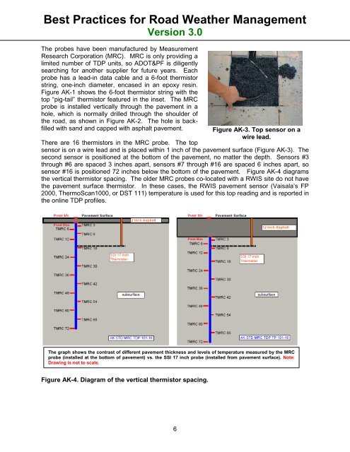
Best Practices for <strong>Road</strong> <strong>Weather</strong> <strong>Management</strong>Version 3.0The probes have been manufactured by MeasurementResearch Corporation (MRC). MRC is only providing alimited number of TDP units, so ADOT&PF is diligentlysearching for another supplier for future years. Eachprobe has a lead-in data cable and a 6-foot thermistorstring, one-inch diameter, encased in an epoxy resin.Figure AK-1 shows the 6-foot thermistor string with thetop “pig-tail” thermistor featured in the inset. The MRCprobe is installed vertically through the pavement in ahole, which is normally drilled through the shoulder ofthe road, as shown in Figure AK-2. The hole is backfilledwith sand and capped with asphalt pavement.Figure AK-3. Top sensor on awire lead.There are 16 thermistors in the MRC probe. The topsensor is on a wire lead and is placed within 1 inch of the pavement surface (Figure AK-3). Thesecond sensor is positioned at the bottom of the pavement, no matter the depth. Sensors #3through #6 are spaced 3 inches apart, sensors #7 through #16 are spaced 6 inches apart, sosensor #16 is positioned 72 inches below the bottom of the pavement. Figure AK-4 diagramsthe vertical thermistor spacing. The older MRC probes co-located with a RWIS site do not havethe pavement surface thermistor. In these cases, the RWIS pavement sensor (Vaisala’s FP2000, ThermoScan1000, or DST 111) temperature is used for this top reading and is reported inthe online TDP profiles.The graph shows the contrast of different pavement thickness and levels of temperature measured by the MRCprobe (installed at the bottom of pavement) vs. the SSI 17 inch probe (installed from pavement surface). Note:Drawing is not to scale.Figure AK-4. Diagram of the vertical thermistor spacing.6