Road Weather Management Program - FHWA Operations - U.S. ...
Road Weather Management Program - FHWA Operations - U.S. ...
Road Weather Management Program - FHWA Operations - U.S. ...

You also want an ePaper? Increase the reach of your titles
YUMPU automatically turns print PDFs into web optimized ePapers that Google loves.
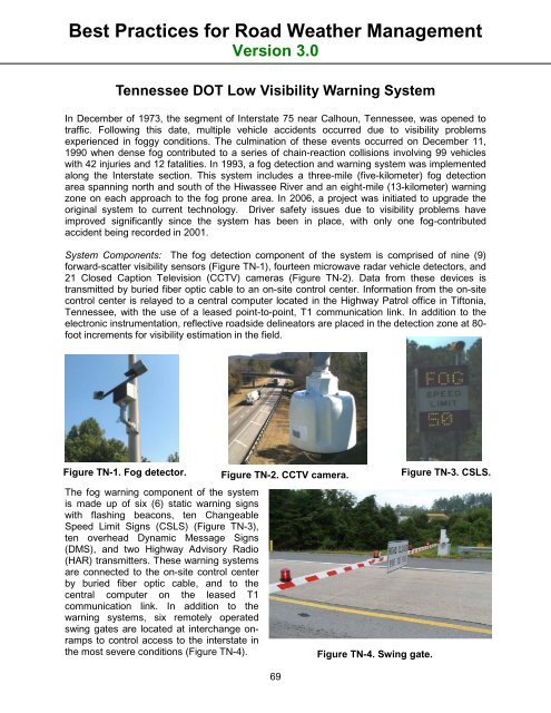
Best Practices for <strong>Road</strong> <strong>Weather</strong> <strong>Management</strong>Version 3.0Tennessee DOT Low Visibility Warning SystemIn December of 1973, the segment of Interstate 75 near Calhoun, Tennessee, was opened totraffic. Following this date, multiple vehicle accidents occurred due to visibility problemsexperienced in foggy conditions. The culmination of these events occurred on December 11,1990 when dense fog contributed to a series of chain-reaction collisions involving 99 vehicleswith 42 injuries and 12 fatalities. In 1993, a fog detection and warning system was implementedalong the Interstate section. This system includes a three-mile (five-kilometer) fog detectionarea spanning north and south of the Hiwassee River and an eight-mile (13-kilometer) warningzone on each approach to the fog prone area. In 2006, a project was initiated to upgrade theoriginal system to current technology. Driver safety issues due to visibility problems haveimproved significantly since the system has been in place, with only one fog-contributedaccident being recorded in 2001.System Components: The fog detection component of the system is comprised of nine (9)forward-scatter visibility sensors (Figure TN-1), fourteen microwave radar vehicle detectors, and21 Closed Caption Television (CCTV) cameras (Figure TN-2). Data from these devices istransmitted by buried fiber optic cable to an on-site control center. Information from the on-sitecontrol center is relayed to a central computer located in the Highway Patrol office in Tiftonia,Tennessee, with the use of a leased point-to-point, T1 communication link. In addition to theelectronic instrumentation, reflective roadside delineators are placed in the detection zone at 80-foot increments for visibility estimation in the field.Figure TN-1. Fog detector.The fog warning component of the systemis made up of six (6) static warning signswith flashing beacons, ten ChangeableSpeed Limit Signs (CSLS) (Figure TN-3),ten overhead Dynamic Message Signs(DMS), and two Highway Advisory Radio(HAR) transmitters. These warning systemsare connected to the on-site control centerby buried fiber optic cable, and to thecentral computer on the leased T1communication link. In addition to thewarning systems, six remotely operatedswing gates are located at interchange onrampsto control access to the interstate inthe most severe conditions (Figure TN-4).Figure TN-2. CCTV camera.69Figure TN-4. Swing gate.Figure TN-3. CSLS.