- Page 2 and 3:
Software Design
- Page 4 and 5:
Software DesignDavid Budgen
- Page 7 and 8:
viContentsChapter 4 Design Qualitie
- Page 9 and 10:
viiiContentsChapter 16 Designing wi
- Page 11 and 12:
xPreface to the second editiondescr
- Page 13 and 14:
xiiPreface to the First EditionWhy
- Page 15 and 16:
xivPreface to the first editionto t
- Page 17 and 18:
xviPublisher’s AcknowledgementsWe
- Page 20 and 21:
chapter 13The Nature of the Design
- Page 22 and 23:
Design is just as important with so
- Page 24 and 25:
Initialobservations7More systematic
- Page 26 and 27:
development. However, it should als
- Page 28 and 29:
From this relatively simple case st
- Page 30 and 31:
nnWhere possible, the panels used i
- Page 32 and 33:
It might well be argued that while
- Page 34 and 35:
system being developed. Clearly, in
- Page 36 and 37:
case study, the outline plan on squ
- Page 38 and 39:
nnnWicked problems do not have an e
- Page 40:
on to Pittsburgh. Airline B is the
- Page 43 and 44:
262.1 What is software?The software
- Page 45 and 46:
28nChangeability. Software suffers
- Page 47 and 48:
30The software design processFigure
- Page 49 and 50:
32The software design processthat a
- Page 51 and 52:
34The software design processFigure
- Page 53 and 54:
36The software design processFigure
- Page 55 and 56:
38The software design processproces
- Page 57 and 58:
40The software design processform p
- Page 59 and 60:
42The software design processFigure
- Page 61 and 62:
44The software design process2.3 De
- Page 63 and 64:
463.1 A context for designDesign in
- Page 65 and 66:
48Design in the software developmen
- Page 67 and 68:
50Design in the software developmen
- Page 69 and 70:
52Design in the software developmen
- Page 71 and 72:
54A personal itchDesign in the soft
- Page 73 and 74:
56Design in the software developmen
- Page 75 and 76:
58Design in the software developmen
- Page 77 and 78:
60nthe associated role of requireme
- Page 80 and 81:
chapter 463Design Qualities4.1 The
- Page 82 and 83:
is virtually impossible to modify i
- Page 84 and 85:
measurable characteristic that can
- Page 86 and 87:
69Assessing design qualityFigure 4.
- Page 88 and 89:
nnnnreliabilityefficiencymaintainab
- Page 90 and 91:
Table 4.1The cognitive dimensions73
- Page 92 and 93:
system. The results of this study u
- Page 94 and 95:
nnnmodules are easy to replace;each
- Page 96 and 97: Table 4.3The principal forms of coh
- Page 98 and 99: Identifying attributes that are the
- Page 100 and 101: Our study of the nature of the desi
- Page 102: nTechnical design reviews can provi
- Page 106 and 107: chapter 589Describing a Design Solu
- Page 108 and 109: 91Figure 5.1Example of a ‘physica
- Page 110 and 111: term is used to describe ‘stakeho
- Page 112 and 113: 95Design viewpoints for softwareFig
- Page 114 and 115: nnof mark-up languages such as HTML
- Page 116 and 117: nnntextdiagramsmathematical express
- Page 118 and 119: happens with pioneering ideas, it h
- Page 120: I have termed ‘derived viewpoints
- Page 123 and 124: 1066.1 The need to share knowledgeT
- Page 125 and 126: 108Transferring design knowledge6.1
- Page 127 and 128: 110then briefly consider how the co
- Page 129 and 130: 112Transferring design knowledgethe
- Page 131 and 132: 114Transferring design knowledge6.2
- Page 133 and 134: 116mainTransferring design knowledg
- Page 135 and 136: 118Transferring design knowledgennn
- Page 137 and 138: 120Transferring design knowledgeOne
- Page 139 and 140: 1226.5 A unified interpretation?Tra
- Page 141 and 142: 124Transferring design knowledgeA s
- Page 144 and 145: chapter 7127Some Design Representat
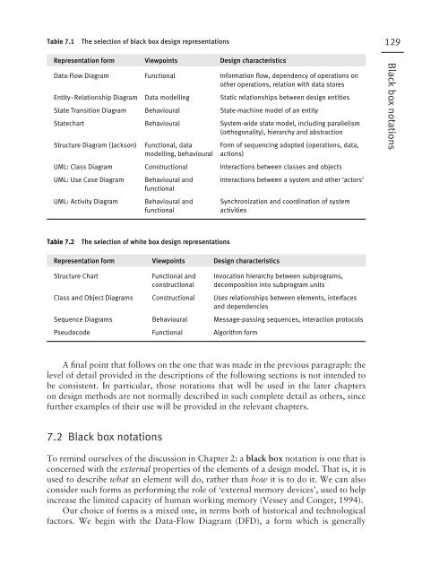
- Page 148 and 149: 131Black box notationsFigure 7.1A f
- Page 150 and 151: 133Black box notationsFigure 7.3mac
- Page 152 and 153: 135Black box notationsFigure 7.4A
- Page 154 and 155: nattributes are classes of values t
- Page 156 and 157: The ERD viewpointERDs are purely an
- Page 158 and 159: 141Black box notationsFigure 7.10A
- Page 160 and 161: 7.2.4 The StatechartLike the STD th
- Page 162 and 163: 145Black box notationsFigure 7.13St
- Page 164 and 165: 7.2.5 The Jackson Structure Diagram
- Page 166 and 167: 149Black box notationsFigure 7.17 A
- Page 168 and 169: 151Black box notationsFigure 7.19A
- Page 170 and 171: 153Figure 7.21The UML class notatio
- Page 172 and 173: 155Use case (title indicates the ac
- Page 174 and 175: 157cardrejectedprocesscardcard acce
- Page 176 and 177: 159White box notationsFigure 7.27A
- Page 178 and 179: only the presence of the latter is
- Page 180 and 181: In its most simple form, such a com
- Page 182 and 183: NarrativeUser starts web browserUse
- Page 184 and 185: If anything, pseudocode is used rat
- Page 186 and 187: Many notations can be conveniently
- Page 188 and 189: 171Developing a diagramFigure 7.38E
- Page 190 and 191: Stevens P. with Pooley R. (2000). U
- Page 192 and 193: chapter 8175The Rationale for Metho
- Page 194 and 195: provide a methodological analysis o
- Page 196 and 197:
179Figure 8.2nnSome properties of f
- Page 198 and 199:
ones that may be usefully supported
- Page 200 and 201:
183Figure 8.3The use of virtual mac
- Page 202 and 203:
In particular, the use of a design
- Page 204 and 205:
need to be recognized. Unfortunatel
- Page 206 and 207:
A somewhat different approach to cl
- Page 208:
Exercises1918.1 How would you class
- Page 211 and 212:
1949.1 The role of strategy in meth
- Page 213 and 214:
196Design processes and design stra
- Page 215 and 216:
198Design processes and design stra
- Page 217 and 218:
200Design processes and design stra
- Page 219 and 220:
202Design processes and design stra
- Page 221 and 222:
204Design processes and design stra
- Page 223 and 224:
206Design processes and design stra
- Page 225 and 226:
208Design processes and design stra
- Page 227 and 228:
210Design processes and design stra
- Page 229 and 230:
212ExercisesDesign processes and de
- Page 231 and 232:
21410.1 Design by template and desi
- Page 233 and 234:
216Design patternspatterns for obje
- Page 235 and 236:
218Design patternsFigure 10.1A simp
- Page 237 and 238:
220Design patternsnnnnnnnnnnnName u
- Page 239 and 240:
222Design patternsFigure 10.3The pr
- Page 241 and 242:
224ClientRequesthandlerDesign patte
- Page 243 and 244:
226Design patternsout how to produc
- Page 245 and 246:
2281Design patternsRequirementsPatt
- Page 247 and 248:
230Design patternsThe patterns comm
- Page 250 and 251:
chapter 11233Stepwise Refinement11.
- Page 252 and 253:
2. The degree of modularity resulti
- Page 254 and 255:
compiler237lexical analysisFigure 1
- Page 256:
Further reading239Wirth N. (1971).
- Page 259 and 260:
24212.1 Black box to white box in s
- Page 261 and 262:
244well be to deliver a solution on
- Page 263 and 264:
246Incremental designpossible model
- Page 265 and 266:
248Incremental designnnthe roles, r
- Page 267 and 268:
250Incremental designFunctionalityT
- Page 269 and 270:
252Incremental designBusinessstudyF
- Page 271 and 272:
254Incremental designalthough it ma
- Page 273 and 274:
256ExercisesIncremental design12.1
- Page 275 and 276:
25813.1 Origins, development and ph
- Page 277 and 278:
260Structured systems analysis and
- Page 279 and 280:
262Structured systems analysis and
- Page 281 and 282:
264Structured systems analysis and
- Page 283 and 284:
266Structured systems analysis and
- Page 285 and 286:
268Structured systems analysis and
- Page 287 and 288:
270Structured systems analysis and
- Page 289 and 290:
272Structured systems analysis and
- Page 291 and 292:
274Structured systems analysis and
- Page 293 and 294:
276Structured systems analysis and
- Page 295 and 296:
278Structured systems analysis and
- Page 297 and 298:
280Structured systems analysis and
- Page 299 and 300:
282Structured systems analysis and
- Page 301 and 302:
284Structured systems analysis and
- Page 303 and 304:
286Structured systems analysis and
- Page 305 and 306:
288ExercisesStructured systems anal
- Page 307 and 308:
29014.1 Some background to JSPJacks
- Page 309 and 310:
292Jackson Structured Programming (
- Page 311 and 312:
294Jackson Structured Programming (
- Page 313 and 314:
296Jackson Structured Programming (
- Page 315 and 316:
298Jackson Structured Programming (
- Page 317 and 318:
300Jackson Structured Programming (
- Page 319 and 320:
302Jackson Structured Programming (
- Page 321 and 322:
304Jackson Structured Programming (
- Page 323 and 324:
306Jackson Structured Programming (
- Page 325 and 326:
308Jackson Structured Programming (
- Page 327 and 328:
310Jackson Structured Programming (
- Page 329 and 330:
312Jackson Structured Programming (
- Page 332 and 333:
chapter 15315Jackson System Develop
- Page 334 and 335:
317The JSD modelFigure 15.1Top-leve
- Page 336 and 337:
319Figure 15.3Generic form of ESD.t
- Page 338 and 339:
321Figure 15.6Process 1.The SSD for
- Page 340 and 341:
323The JSD processFigure 15.9 The J
- Page 342 and 343:
Entity analysis (the entity-action
- Page 344 and 345:
327The JSD processFigure 15.13The J
- Page 346 and 347:
329The JSD processFigure 15.14 The
- Page 348 and 349:
331The JSD processFigure 15.15 The
- Page 350 and 351:
333The JSD processFigure 15.16The c
- Page 352 and 353:
Information function step335From a
- Page 354 and 355:
The situation is analogous to that
- Page 356:
Exercises33915.1 Construct an ESD t
- Page 359 and 360:
34216.1 The ‘object concept’Des
- Page 361 and 362:
344Designing with objectsThe evolut
- Page 363 and 364:
346Designing with objectsFigure 16.
- Page 365 and 366:
348Designing with objectsFor the ob
- Page 367 and 368:
350Designing with objectsFigure 16.
- Page 369 and 370:
352 Executable units of code(subpro
- Page 371 and 372:
354A summary of the core concepts o
- Page 373 and 374:
356Designing with objectsnnnnnnnorg
- Page 375 and 376:
358Designing with objectsA rather l
- Page 377 and 378:
360Designing with objects16.2.1 Sur
- Page 379 and 380:
362Designing with objectsFigure 16.
- Page 381 and 382:
364closely at the representation pa
- Page 383 and 384:
366Designing with objectsAn empiric
- Page 385 and 386:
368Designing with objectsof a frame
- Page 387 and 388:
370Designing with objects16.3.2 Des
- Page 389 and 390:
372Designing with objectsDepartment
- Page 391 and 392:
374Designing with objectsFigure 16.
- Page 393 and 394:
376Designing with objects1. The obj
- Page 395 and 396:
378Designing with objectsdescribe a
- Page 397 and 398:
380Designing with objectsnnapproach
- Page 399 and 400:
382Designing with objectssequence d
- Page 401 and 402:
384Designing with objectsnnhow is t
- Page 403 and 404:
386step, it is those analysis-relat
- Page 405 and 406:
388Designing with objectsStep 7: De
- Page 407 and 408:
390Designing with objectsbehaviour,
- Page 409 and 410:
392indicate the degree of effort. A
- Page 411 and 412:
394Designing with objectsThe UP wor
- Page 413 and 414:
396Designing with objectsFigure 16.
- Page 415 and 416:
398Designing with objectsSimilarly,
- Page 417 and 418:
400Designing with objectswww.omg.or
- Page 419 and 420:
40217.1 The component conceptCompon
- Page 421 and 422:
404Component-based designmore than
- Page 423 and 424:
406Component-based designFigure 17.
- Page 425 and 426:
408Component-based designto address
- Page 427 and 428:
410Component-based designnto decomp
- Page 429 and 430:
412Component-based design4. Archite
- Page 431 and 432:
41417.3 Designing componentsCompone
- Page 433 and 434:
416Component-based designSourceInde
- Page 435 and 436:
418Component-based designwww.sei.ed
- Page 437 and 438:
42018.1 The case for rigourA formal
- Page 439 and 440:
422A formal approach to designmight
- Page 441 and 442:
424A formal approach to designFigur
- Page 443 and 444:
426A formal approach to design18.2.
- Page 445 and 446:
428 Table 18.1 Set operations used
- Page 447 and 448:
430A formal approach to designClear
- Page 449 and 450:
432InitResSystA formal approach to
- Page 451 and 452:
434A formal approach to designFigur
- Page 453 and 454:
436A formal approach to designFigur
- Page 455 and 456:
438A formal approach to designThis
- Page 457 and 458:
44018.2 Write simple Z specificatio
- Page 459 and 460:
44219.1 What is software now?Whithe
- Page 461 and 462:
444Whither software design?Figure 1
- Page 463 and 464:
446Whither software design?Figure 1
- Page 465 and 466:
448Whither software design?Another
- Page 468 and 469:
451BibliographyAbbott R.J. (1983).
- Page 470 and 471:
Buxton J. and McDermid J. (1992). H
- Page 472 and 473:
Guindon R. (1990). Designing the de
- Page 474 and 475:
Perry D.E. and Wolf A.L. (1992). Fo
- Page 476:
Ward P.T. and Mellor S.J. (1985). S
- Page 479 and 480:
462IndexCcall and return (architect
- Page 481 and 482:
464Indexgraphical user interface (G
- Page 483 and 484:
466Indexprogram design 290program i
- Page 485:
468WYIndexwalkthrough 81waterfall m


