surface fitting approach for tensile membranes design - Tecnun
surface fitting approach for tensile membranes design - Tecnun
surface fitting approach for tensile membranes design - Tecnun

Create successful ePaper yourself
Turn your PDF publications into a flip-book with our unique Google optimized e-Paper software.
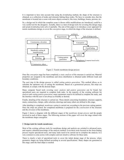
It is important to have into account that using the <strong>for</strong>mfinding method, the shape of the structure isobtained, as a collection of nodes and elements linking these nodes. We have to consider also, that themembrane is located into a scene with more objects around it, like trees, buildings, beams, persons, etc.So, a <strong>design</strong> tool in which the complete scene is shown while modifications are introduced, could be avery useful tool <strong>for</strong> the <strong>design</strong>ers. Actually, there is a lack of <strong>design</strong> tools <strong>for</strong> covering this <strong>design</strong> stage,and actual <strong>for</strong>mfinding tools solve it partially. The aim of this paper is to introduce a new <strong>approach</strong> <strong>for</strong><strong>tensile</strong> <strong>membranes</strong> <strong>design</strong>, to cover the conception stage, in which the shape of the structure is defined.Requerimentsarchitectslack of <strong>design</strong> toolsConstruction, elevationConceptionMembrane cutting &manufacturingDetailingConstructors, othersCutting patterngenerationAnalysisFormFindingEngineers (Computer based tools)Figure 2. Tensile membrane <strong>design</strong> processOnce the conception stage has been completed, a static analysis of the structure is carried out. Materialproperties are assigned to the membrane and stress distribution is obtained under different loads andboundary conditions.The next step in the <strong>design</strong> process is called cutting pattern generation. This method allows us tocalculate the optimum way of cutting the membrane. Based on a geometrical process, flat strips areobtained, to comply with the desired shape.Many computer based tools covering static analysis and pattern generation can be found, butspecialized users are required to complete both tasks. In the majority of the existing software <strong>for</strong>analysis and cutting pattern generation, many parameters need to be defined to complete the study, andthe interface with the user is not always as friendly as desired.Finally, detailing of the structure is carried out. Those details concerning foundation, structure supports,masts, connections, clamps, cable selection, drawings and many others are defined in this stage.After detailing is completed, membrane cutting is carried out, according to the previous cutting pattern.Once the strips are joined, the completed membrane is prepared <strong>for</strong> the construction of the structureand the elevation of the membrane.Figure 2 shows a diagram with the different stages of the membrane <strong>design</strong> process and the peopleinvolved in each of these stages. The following sections of this paper will cover the stage related withthe membrane shape conception.2 Design tools <strong>for</strong> <strong>tensile</strong> <strong>membranes</strong>Most of the existing software tools <strong>for</strong> membrane <strong>design</strong> and analysis are oriented to advanced users,and require a detailed knowledge of the analysis method. Even those tools focused on the <strong>for</strong>m-findingprocess require specialized users, and many tasks need to be carried out to complete the analysis. It isvery common to come across with complex and non intuitive software <strong>for</strong> these tasks.There is clearly a lack of specialized tools to cover the initial <strong>design</strong> stage of the process, wheregeometric shapes are being defined according to several specifications. Many shapes are generated atthis stage, until the final shape is reached.