surface fitting approach for tensile membranes design - Tecnun
surface fitting approach for tensile membranes design - Tecnun
surface fitting approach for tensile membranes design - Tecnun

You also want an ePaper? Increase the reach of your titles
YUMPU automatically turns print PDFs into web optimized ePapers that Google loves.
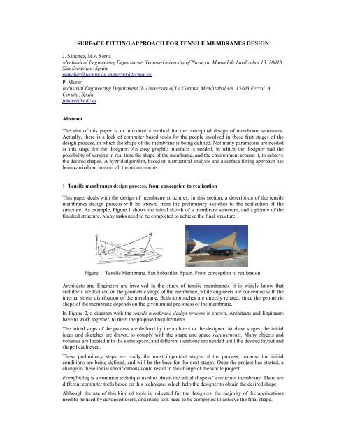
SURFACE FITTING APPROACH FOR TENSILE MEMBRANES DESIGNJ. Sánchez, M.A SernaMechanical Engineering Department- <strong>Tecnun</strong>-University of Navarra. Manuel de Lardizabal 13. 20018San Sebastian. Spain.jsanchez@tecnun.es, maserna@tecnun.esP. MorerIndustrial Engineering Department II- University of La Coruña. Mendizabal s/n. 15403 Ferrol. ACoruña. Spain.pmorer@udc.esAbstractThe aim of this paper is to introduce a method <strong>for</strong> the conceptual <strong>design</strong> of membrane structures.Actually, there is a lack of computer based tools <strong>for</strong> the people involved in these first stages of the<strong>design</strong> process, in which the shape of the membrane is being defined. Not many parameters are neededat this stage <strong>for</strong> the <strong>design</strong>er. An easy graphic interface is needed, in which the <strong>design</strong>er had thepossibility of varying in real time the shape of the membrane, and the environment around it, to achievethe desired shapes. A hybrid algorithm, based on a structural analysis and a <strong>surface</strong> <strong>fitting</strong> <strong>approach</strong> hasbeen carried out to meet all the requirements.1 Tensile <strong>membranes</strong> <strong>design</strong> process, from conception to realizationThis paper deals with the <strong>design</strong> of membrane structures. In this section, a description of the <strong>tensile</strong><strong>membranes</strong> <strong>design</strong> process will be shown, from the preliminary sketches to the realization of thestructure. As example, Figure 1 shows the initial sketch of a membrane structure, and a picture of thefinished structure. Many tasks need to be completed to achieve the final structure.Figure 1. Tensile Membrane. San Sebastián. Spain. From conception to realization.Architects and Engineers are involved in the study of <strong>tensile</strong> <strong>membranes</strong>. It is widely know thatarchitects are focused on the geometric shape of the membrane, while engineers are concerned with theinternal stress distribution of the membrane. Both <strong>approach</strong>es are directly related, since the geometricshape of the membrane depends on the given initial pre-stress of the membrane.In Figure 2, a diagram with the <strong>tensile</strong> membrane <strong>design</strong> process is shown. Architects and Engineershave to work together, to meet the proposed requirements.The initial steps of the process are defined by the architect or the <strong>design</strong>er. At these stages, the initialideas and sketches are drawn, to comply with the shape and space requirements. Many objects andvolumes are located into the same space, and different iterations are needed until the desired layout andshape is achieved.These preliminary steps are really the most important stages of the process, because the initialconditions are being defined, and will be the base <strong>for</strong> the next stages. Once the project has started, achange in these initial specifications could result in the change of the whole project.Formfinding is a common technique used to obtain the initial shape of a structure membrane. There aredifferent computer tools based on this technique, which help the <strong>design</strong>er to obtain the desired shape.Although the use of this kind of tools is indicated <strong>for</strong> the <strong>design</strong>ers, the majority of the applicationsneed to be used by advanced users, and many task need to be completed to achieve the final shape.
It is important to have into account that using the <strong>for</strong>mfinding method, the shape of the structure isobtained, as a collection of nodes and elements linking these nodes. We have to consider also, that themembrane is located into a scene with more objects around it, like trees, buildings, beams, persons, etc.So, a <strong>design</strong> tool in which the complete scene is shown while modifications are introduced, could be avery useful tool <strong>for</strong> the <strong>design</strong>ers. Actually, there is a lack of <strong>design</strong> tools <strong>for</strong> covering this <strong>design</strong> stage,and actual <strong>for</strong>mfinding tools solve it partially. The aim of this paper is to introduce a new <strong>approach</strong> <strong>for</strong><strong>tensile</strong> <strong>membranes</strong> <strong>design</strong>, to cover the conception stage, in which the shape of the structure is defined.Requerimentsarchitectslack of <strong>design</strong> toolsConstruction, elevationConceptionMembrane cutting &manufacturingDetailingConstructors, othersCutting patterngenerationAnalysisFormFindingEngineers (Computer based tools)Figure 2. Tensile membrane <strong>design</strong> processOnce the conception stage has been completed, a static analysis of the structure is carried out. Materialproperties are assigned to the membrane and stress distribution is obtained under different loads andboundary conditions.The next step in the <strong>design</strong> process is called cutting pattern generation. This method allows us tocalculate the optimum way of cutting the membrane. Based on a geometrical process, flat strips areobtained, to comply with the desired shape.Many computer based tools covering static analysis and pattern generation can be found, butspecialized users are required to complete both tasks. In the majority of the existing software <strong>for</strong>analysis and cutting pattern generation, many parameters need to be defined to complete the study, andthe interface with the user is not always as friendly as desired.Finally, detailing of the structure is carried out. Those details concerning foundation, structure supports,masts, connections, clamps, cable selection, drawings and many others are defined in this stage.After detailing is completed, membrane cutting is carried out, according to the previous cutting pattern.Once the strips are joined, the completed membrane is prepared <strong>for</strong> the construction of the structureand the elevation of the membrane.Figure 2 shows a diagram with the different stages of the membrane <strong>design</strong> process and the peopleinvolved in each of these stages. The following sections of this paper will cover the stage related withthe membrane shape conception.2 Design tools <strong>for</strong> <strong>tensile</strong> <strong>membranes</strong>Most of the existing software tools <strong>for</strong> membrane <strong>design</strong> and analysis are oriented to advanced users,and require a detailed knowledge of the analysis method. Even those tools focused on the <strong>for</strong>m-findingprocess require specialized users, and many tasks need to be carried out to complete the analysis. It isvery common to come across with complex and non intuitive software <strong>for</strong> these tasks.There is clearly a lack of specialized tools to cover the initial <strong>design</strong> stage of the process, wheregeometric shapes are being defined according to several specifications. Many shapes are generated atthis stage, until the final shape is reached.
Figure 3 shows some pictures in which <strong>tensile</strong> <strong>membranes</strong> are combined with other shapes and objectsin the same scene. In this example, a space needs to be covered using <strong>tensile</strong> <strong>membranes</strong> structures.Two rectangular shapes represent the buildings. On the left side, a row of columns delimit the centralspace. This could be a usual statement of a project, and many layouts can be obtained until the finalshape is reached. One or more <strong>membranes</strong> could be used to cover the space. So, it is not only necessaryto calculate each of the shapes, but also to orient and place them in the appropriate position. The shapeof any membrane should be recalculated in real time, as the position of the vertex is modified by the<strong>design</strong>er. A flexible tool is required to achieve all these requirements, and a complete view of the sceneis needed to obtain an appropriate solution.In the left side of Figure 3, an initial sketch of the desired layout is drawn. In the right side, usingcomputer based techniques, a solution has been reached to comply with the initial requirements. Twopossible layouts are shown, with three (a) and four (b) <strong>membranes</strong>.(a)(b)Figure 3 Example of <strong>design</strong> tool scene <strong>for</strong> <strong>tensile</strong> <strong>membranes</strong>.(a) three <strong>membranes</strong> layout (b) four <strong>membranes</strong> layout.We will use this example to enumerate different features that a software tool should offer to the<strong>design</strong>er. The application should allow the <strong>design</strong>er the possibility of drag and drop any object of thescene, and obtain the new shape of the membrane in real-time. Each membrane has different materialproperties, boundary conditions and applied loads. In the same environment, many <strong>membranes</strong> shapesare evaluated in real-time and the complete scene offers the <strong>design</strong>er a whole integration of thestructure with the objects around it. So, <strong>for</strong>mfinding is only a stage in the <strong>design</strong> process.Other features of interest could be: easy to use, flexible enough to modify any object in the scene,material library, predefined objects with various shapes and sizes, open to CAD systems (neutral<strong>for</strong>mats like dxf, iges or step), and Windows based controls to obtain a user-friendly environment.These could be the requirements <strong>for</strong> most of the <strong>design</strong>ers. In the next section, a computational methodis described, that would cover the described requirements <strong>for</strong> the <strong>design</strong> tool.3 Hybrid method <strong>for</strong> <strong>tensile</strong> membrane <strong>design</strong>As described be<strong>for</strong>e, a combined method <strong>for</strong> membrane calculation has been per<strong>for</strong>med. The methodcombines structural behavior (<strong>for</strong>mfinding) and geometry (<strong>surface</strong> <strong>fitting</strong>) to offer a robust and fastmethod <strong>for</strong> <strong>tensile</strong> membrane <strong>design</strong> and analysis.Basically, the method consists in the representation of the membrane structure using a parametric<strong>surface</strong>. This <strong>surface</strong> is based on the results of the previous structural analysis.The process diagram of the hybrid method proposed is shown in Figure 4.
The membrane structure has been modeled by means of a cable network. The first task consists in thegeneration of an initial grid, with nodes and elements connecting these nodes.In the next step, the equilibrium shape of the membrane is calculated using a <strong>for</strong>mfinding method or anon linear <strong>approach</strong>. More details about these equilibrium methods are given later. A new position <strong>for</strong>the nodes is obtained, that satisfy this equilibrium shape.Grid Generation Form-finding Surface <strong>fitting</strong> RenderFigure 4.- Hybrid method proposed <strong>for</strong> <strong>tensile</strong> membrane <strong>design</strong>Once the nodes have reached the equilibrium state, a parametric <strong>surface</strong> that passes through the givennodes is generated. This process is called <strong>surface</strong> <strong>fitting</strong>, and will be described later.Finally, a render representation of the membrane can be obtained from the previous parametric <strong>surface</strong>.Figure 5 shows graphically and example of the steps described <strong>for</strong> the proposed method. In thisexample, a 3x3 grid (a) has been used to obtain the equilibrium shape (b) of the membrane. From thisequilibrium shape, a parametric <strong>surface</strong> is obtained (c) and a render representation of the membrane hasbeen generated (d).(a)(b)(c ) (d)Figure 5. Hybrid method <strong>for</strong> <strong>tensile</strong> membrane <strong>design</strong>. (a) Grid Generation,(b) <strong>for</strong>mfinding, (c) Surface <strong>fitting</strong>, (d) render representation
The analysis of <strong>tensile</strong> structures is a geometrically non-linear problem, and consists on finding theequilibrium shape compatible with the given prestress conditions. The process of determining thisinitial equilibrium shape is known as <strong>for</strong>mfinding.In computer analysis, the membrane is divided in a discrete number of elements, joined at nodes.Material properties and loads are defined at a discrete number of locations. Some nodes may berestrained, and others are free to translate and rotate.Form finding Methods <strong>for</strong> <strong>tensile</strong> <strong>membranes</strong> analysisMany methods of analysis have been implemented in the last years, in order to study <strong>tensile</strong><strong>membranes</strong> behavior. Force Density Method [SHE74], Surface Stress Density Method [MAU98] andDynamic Relaxation [BAR99] are the most common ones used <strong>for</strong> the <strong>for</strong>m-finding process.Force Density Method uses an analytic technique to linearize the <strong>for</strong>m finding equations <strong>for</strong> a tensionnet. This linearization makes the method independent of the material properties of the membrane. Forcedensity ratios (cable <strong>for</strong>ce divided by cable length) need to be specified <strong>for</strong> each element, and differentratios give different equilibrium shapes. The method is numerically robust, independent of the initiallocations of the nodes, and the equilibrium shape is found easily. The <strong>for</strong>ce density solution to appliedloads is non-linear, and requires iteration.Surface Stress Density Method can be considered as a generalization of linear <strong>for</strong>ce density method tothe bidimensional case, and takes into account the shear stress. In this case, the <strong>surface</strong> stress densityratio is given by the stress divided by the area of the element.Dinamic Relaxation method solves the geometric non-linear problem by equating it to a dynamicproblem. Principles of dynamic are used to solve the analysis. Appropriate dynamic properties need tobe defined, like the mass and damping characteristics of the membrane. A balance of <strong>for</strong>ces is made ateach node, giving a residual <strong>for</strong>ce that produces the movement of the node in the direction of this <strong>for</strong>ce,according to the dynamic behavior of the net. New positions <strong>for</strong> the nodes are calculated until the finalequilibrium shape is reached. At this point the residual <strong>for</strong>ces are sufficiently small.Non linear <strong>approach</strong> <strong>for</strong> <strong>tensile</strong> <strong>membranes</strong> analysisAs described be<strong>for</strong>e, the analysis of <strong>tensile</strong> structures is a geometrically non-linear problem. Thestiffness method solves a set of equations (1) that represents the translational and rotational equilibriumat each node of the structure.P = K ⋅ U(1)[ ] [ ] [ ]where [P] is the applied nodal loads vector; [K] is the Stiffness Matrix; and [U] is the Nodaldisplacement vector.This method required an iterative process, until equilibrium shape compatible with the given prestressconditions is reached. At each step, a global stiffness matrix is recalculated, according to the newposition of the nodes, and the material properties of the membrane. Applied loads are considered in theanalysis.Surface <strong>fitting</strong> <strong>approach</strong>Once the equilibrium shape has been reached by any of the method described be<strong>for</strong>e, the <strong>surface</strong> <strong>fitting</strong><strong>approach</strong> is carried out. The geometry of a membrane structure can be easily represented using aparametric <strong>surface</strong>. Once the nodes have reached the equilibrium state, a parametric <strong>surface</strong> that passesthrough the given nodes is generated. This process is called <strong>surface</strong> <strong>fitting</strong>.At this stage, the control net is calculated from the position of the nodes at the equilibrium state. Theshape of the parametric <strong>surface</strong> depends on this control net. Final shape of the <strong>surface</strong> is given afterevaluating the expression (2), <strong>for</strong> Non-uni<strong>for</strong>m Rational B-Splines (NURBS).hBi , jN kn + 1 m+1i=1 j = 1( u,w) = ∑∑Q B(2)hi, jNi,k( u)Mj,l( w)s are the four-dimensional homogeneous control net vertices.i ,( u)and M j , l( w)are the nonrational B-spline basis functions.
Many methods <strong>for</strong> <strong>surface</strong> <strong>fitting</strong> are implemented to obtain the control net from a cloud of points.[ROG89] and [PIE00] describe in detail the technique.Once the parametric <strong>surface</strong> is calculated, the <strong>design</strong>er can obtain the position at any point of themembrane <strong>surface</strong>, not only at the nodes used <strong>for</strong> calculating the equilibrium shape.Not many points are needed to generate a smooth <strong>surface</strong>. In the example shown in Figure 5, a smooth<strong>surface</strong> is obtained from an initial grid of 3x3 by interpolation. The <strong>design</strong>er that manipulates the modelcan easily drag and drop a vertex of the membrane in real time. Many shapes can be obtained, and theuser has the feeling that the membrane is being moving in real time while dragging any point of thestructure by means of the mouse.In Table 1 and Figure 6, computational times <strong>for</strong> calculating the equilibrium shape and <strong>surface</strong> <strong>fitting</strong>are shown.Grid Size Method Time (seconds) Nodes Bars3x3 Force Density 0.033 16 245x5 Force Density 0.049 36 607x7 Force Density 0.061 64 1129x9 Force Density 0.100 100 1803x3 Non-Linear 0.039 16 245x5 Non-Linear 0.078 36 607x7 Non-Linear 0.152 64 1129x9 Non-Linear 0.402 100 180Table 1. Computational times <strong>for</strong> different grid sizes and <strong>for</strong>mfinding methods.0.450.40.350.3Seconds0.250.20.15Force DensityNon Linear0.10.0503x3 5x5 7x7 9x9Grid SizeFigure 6. Computational times <strong>for</strong> different grid sizes and <strong>for</strong>mfinding methods.
Computational times <strong>for</strong> Force Density and Non-Linear method have been calculated. In both methods,the time needed to complete the equilibrium shape and <strong>surface</strong> <strong>fitting</strong> grows with the size of the grid.Common shapes used in membrane structures can be represented with precision by means ofparametric <strong>surface</strong>s from a discrete model of one hundred nodes. Figure 7 shows another example, inwhich a membrane is represented with a grid size of 5x5. In this case, a nodal load is applied.According to table 1, thirty six nodes from the equilibrium shape have been used <strong>for</strong> creating theparametric <strong>surface</strong>.It can be seen that the <strong>design</strong>er needs to reach a compromise between two facts: computational timeneeded to complete the calculation, or the precision obtained. The <strong>design</strong>er has the criteria to decidewhich of these statements is more important during the <strong>design</strong> of a membrane structure. In some cases,fast calculation could be more important that the precision achieved. In any case, the <strong>design</strong>er has thepossibility of increase or decrease easily the number of nodes needed, depending on the criteria adopted.Figure 7 Representation of a membrane structure with a nodal <strong>for</strong>ce using a 5x5 grid. (a)Grid Generation, (b) <strong>for</strong>mfinding, (c) Surface <strong>fitting</strong>, (d) render representation4 Application implementedFigure 8 shows a snapshot of the application implemented to test the proposed method. In the workingarea, the membrane is being displayed in wireframe or shaded style. The user can dynamically translateand rotate the model, or apply a zoom. The position of the membrane vertex can be modified by theuser with the mouse or by means of a slider control, and the new shape of the membrane is calculatedin real-time.Internal prestress values are defined independently in warp and weft direction of the membrane andinternal <strong>for</strong>ces are given <strong>for</strong> each of the edges. Formfinding method can be chosen as indicatedpreviously.Figure 8. Snapshot of the application
Other details, regarding <strong>surface</strong> <strong>fitting</strong> parameters, material properties, applied <strong>for</strong>ces, visualization ofnormal vectors, can be defined.The external distributed <strong>for</strong>ces applied can also vary, and the new membrane shape is calculated inreal-time. Figure 9 shows several membrane shapes obtained <strong>for</strong> different external applied loads,without changing the boundary conditions.5 ConclusionsFigure 9.- Load Sequence, using the same boundary conditionsThe proposed combined method complies with the requirements given <strong>for</strong> the <strong>design</strong> process. It is quitesimple to generate and modify shapes in real-time, assign material, loads or modify the boundaryconditions of the model. A non specialized <strong>design</strong>er can get used to the application in a short time.As said be<strong>for</strong>e, membrane structures shapes are easy to represent using parametric <strong>surface</strong>s, and notmany points are needed to obtain a smooth <strong>surface</strong>. Geometry of common <strong>membranes</strong> structures is notsubject to important changes in curvature or local applied loads as shown in figure 7.Finally, we should highlight again the existing compromise between computation time and precisionneeded. The <strong>design</strong>er should have enough criteria to decide in which cases each is required.References[SHE74] H.J. Sheck, (1974) “The <strong>for</strong>ce density method <strong>for</strong> <strong>for</strong>m-finding and computations of generalnetworks,Mahadevan”, Computer Methods in Applied. Mechanics and Engineering, p.115,134.[MAU98] B. Maurin & R. Motro (1998) “The <strong>surface</strong> stress density method as a <strong>for</strong>m-finding tool <strong>for</strong><strong>tensile</strong> <strong>membranes</strong>”, Engineering Structures, Vol 20, nº8, p.712-719.[BAR97] M.R. Barnes (1999) “Form Finding and Analysis of Tension Structures by DinamicRelaxation”, International Journal of Space Structures, Vol 14, nº2.[ROG89] D.F.Rogers, N.G.Fog (1989) “Constrained B-spline curve and <strong>surface</strong> <strong>fitting</strong>”, ComputerAided Design, Vol 21, No 10, p.641-648[PIE00] L.Piegl, W. Tiller. (2000) “Curve Interpolation with Arbitrary End Derivatives”, Engineeringwith Computers, Vol 16, p.73-79[ROG01] D.F.Rogers (2001) “An Introduction to Nurbs”, Academic Press.[PIE97] L.Piegl, W. Tiller. (1997) “The Nurbs Book”. Second Edition. Springer-Verlag, New York[PIE91] L.Piegl. (1991) “On Nurbs: A survey”, IEEE Computer Graphics & Applications, Vol 11,No 1, p.55-71