Create successful ePaper yourself
Turn your PDF publications into a flip-book with our unique Google optimized e-Paper software.
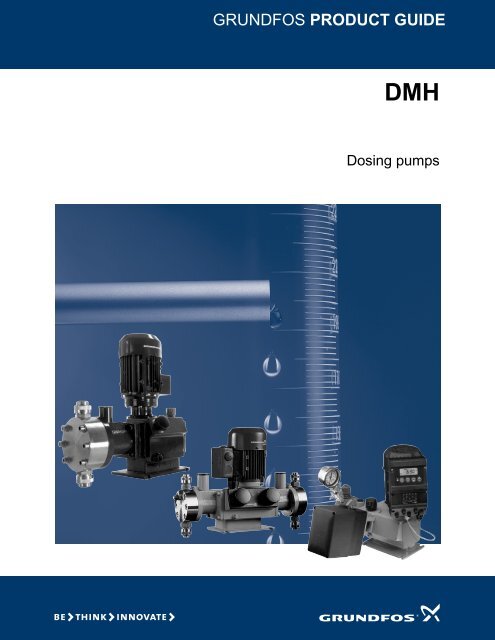
<strong>GRUNDFOS</strong> <strong>PRODUCT</strong> <strong>GUIDE</strong>DMHDosing pumps
ContentsFeatures and benefitsDMH 3Performance rangeDMH 4Pump selectionDMH options 36Pumped liquidsList of pumped liquids 39IdentificationType key 7FunctionsFunctional overview 8Capacity control 8DMH B 8DMH AR 9Control panel 10Connectors 10ConstructionGeneral description 11DMH 251 11DMH 252 12DMH 253 13DMH 254 14DMH 255 15DMH 257 16DMH 280 17DMH 281 18DMH 283 19DMH 285 20DMH 286 21DMH 287 22DMH 288 23Technical dataDimensions, DMH 251-257 24Dimensions, DMH 280-288 26US Connections for suction and discharge 27DMH pumps supplied from the USA 28Motors TEFC AC 1725 RPM 28Servo motors 28Performance data, DMH 251-257 29Performance data, DMH 280-288 30Suction lift, DMH 251-257 31Suction lift, DMH 280-288 32Weights, DMH 251-257 33Weights, DMH 280-288 33Sound pressure 34Accuracy 34Permissible temperature of dosing liquid 34AR control unit, technical data 34Lubricants 352
Features and benefitsDMHDMHHydraulic diaphragm dosingfrom 0.50 to 2 x 278 GPH.The preferred choice for demanding applicationsThe Grundfos DMH range is a series of hydraulicpumps for applications demanding a high-quality pump.With its high accuracy and modern interface possibilities,the DMH is ideal for many applications in watertreatment and industrial processing.Fig. 1 DMHFig. 2 DMH 283 duplex versionTM03 2133 3705TM03 8940 2807Prepared for performance and safety in extreme situationsThe DMH 250 series of pumps is available with PVC,PVDF, polypropylene, stainless steel and Hastelloy Cwetted components. For high-pressure requirements,select from the series of stainless steel or Hastelloy CDMH 280 pumps, rated up to 2900 PSI. All models arefitted with a PTFE diaphragm, with the AMS diaphragmprotection system and internal relief valve for pump protection.Get the pump configuration you needControl the capacity manually by adjusting the strokelength from 0 to 100 %, with a +/- 1 % repeatable accuracy.Additional options:• Duplex version offers twice the capacity of a simplexpump. It is also used for blending applications.• Electric 4-20 mA servomotor (electric actuator) orpneumatic stroke length control• Variable speed drive controller• Integrated stroke sensor and electronic counter• Leak detection with double diaphragm.Typical applications:• Municipal and industrial water treatment• Wastewater treatment• Chemical industry• Boiler feed• Petroleum industry• Filtration systems• pH control• Demineralizers• Pulp & paper• Textile• Food & beverage.Fig. 3 DMH 251 with stroke frequency controller, leakdetector, and remote stroke length controlTM03 8941 2807API 675 modelsDMH 250 and 280 series pumps are available in API675 compatible versions. This is commonly used inpetroleum, chemical refineries, and transmission pipelineapplications. Contact Grundfos for available models.3
Performance rangeDMHDMH0.50 to 278 GPHp[psi]2900DMH60 Hz1450725232145002 11.4 25.3 53.9 63.9278Q [US GPH]TM03 8855 2707Fig. 4 Performance range, DMH, 0.50 to 278 GPH4
Performance rangeDMHPerformance range by max. pressureDMH 250 DMH 280ModelSizeMax.capacity[GPH]Max.pressure[PSI]stokes/min.251 2.4-10 0.77 145 17251 5-10 1.58 145 35251 13-10 4.22 145 75251 19-10 6.07 145 115252 11-10 3.45 145 35252 24-10 7.66 145 75252 37-10 11.62 145 115253 21-10 6.60 145 35253 43-10 13.70 145 75253 67-10 20.60 145 115253 83-10 26.10 145 144254 50-10 15.80 145 32254 102-10 32.20 145 65254 143-10 45.40 145 90254 175-10 55.40 145 110254 213-10 67.30 145 134255 194-10 61.50 145 65255 270-10 85.50 145 90255 332-10 105.00 145 110255 403-10 128.00 145 134257 220-10 69.70 145 33257 440-10 139.40 145 65257 575-10 182.20 145 90257 770-10 244.00 145 110257 880-10 278.00 145 134251 2.3-16 0.74 232 17251 4.9-16 1.55 232 35251 12-16 3.70 232 75251 18-16 5.81 232 115252 10-16 3.17 232 35252 23-16 7.13 232 75252 36-16 11.35 232 115254 97-16 30.60 232 65254 136-16 43.00 232 90254 166-16 52.80 232 110254 202-16 63.90 232 134251 2.2-25 0.69 363 17251 4.5-25 1.43 363 35251 11-25 3.43 363 75251 17-25 5.28 363 115ModelNote: Double GPH with duplex versions.Performance range by modelDMH 251SizeMax.capacity[GPH]Max.pressure[PSI]stokes/min.286 85-50 26.90 725 67286 111-50 35.10 725 88286 170-50 53.90 725 134281 2-100 0.60 1450 35281 4.2-100 1.30 1450 76281 6.4-100 2.00 1450 115281 8-100 2.50 1450 144283 19-100 6.10 1450 65283 27-100 8.40 1450 90283 33-100 10.60 1450 110283 40-100 12.70 1450 134285 20-100 6.30 1450 33285 40-100 12.70 1450 67285 52-100 16.60 1450 88285 70-100 22.20 1450 118285 80-100 25.30 1450 134280 1.3-200 0.50 2900 76280 2.2-200 0.70 2900 115280 2.5-200 0.90 2900 144287 18-200 5.80 2900 67287 23-200 7.40 2900 88287 31-200 9.80 2900 118287 36-200 11.40 2900 134288 7.5-200 2.40 2900 67288 10-200 3.30 2900 88288 13-200 4.10 2900 118288 15-200 4.90 2900 134Size Max. capacity [GPH] Max. pressure [PSI] str./min.2.2-25 0.69 363 172.3-16 0.74 232 172.4-10 0.77 145 174.5-25 1.43 363 354.9-16 1.55 232 355-10 1.58 145 3511-25 3.43 363 7512-16 3.70 232 7513-10 4.22 145 7517-25 5.28 363 11518-16 5.81 232 11519-10 6.07 145 1155
Performance rangeDMHDMH 252Size Max. capacity [GPH] Max. pressure [PSI] str./min.10-16 3.17 232 3511-10 3.45 145 3523-16 7.13 232 7524-10 7.66 145 7536-16 11.35 232 11537-10 11.62 145 115DMH 253Size Max. capacity [GPH] Max. pressure [PSI] str./min.21-10 6.60 145 3543-10 13.70 145 7567-10 20.60 145 11583-10 26.10 145 144DMH 254Size Max. capacity [GPH] Max. pressure [PSI] str./min.50-10 15.80 145 3297-16 30.60 232 65102-10 32.20 145 65136-16 43.00 232 90143-10 45.40 145 90166-16 52.80 232 110175-10 55.40 145 110202-16 63.90 232 134213-10 67.30 145 134DMH 255Size Max. capacity [GPH] Max. pressure [PSI] str./min.194-10 61.50 145 65270-10 85.50 145 90332-10 105.00 145 110403-10 128.00 145 134DMH 257DMH 283Size Max. capacity [GPH] Max. pressure [PSI] str./min.19-100 6.10 1450 6527-100 8.40 1450 9033-100 10.60 1450 11040-100 12.70 1450 134DMH 285Size Max. capacity [GPH] Max. pressure [PSI] str./min.20-100 6.30 1450 3340-100 12.70 1450 6752-100 16.60 1450 8870-100 22.20 1450 11880-100 25.30 1450 134DMH 286Size Max. capacity [GPH] Max. pressure [PSI] str./min.85-50 26.90 725 67111-50 35.10 725 88170-50 53.90 725 134DMH 287Size Max. capacity [GPH] Max. pressure [PSI] str./min.18-200 5.80 2900 6723-200 7.40 2900 8831-200 9.80 2900 11836-200 11.40 2900 134DMH 288Size Max. capacity [GPH] Max. pressure [PSI] str./min.7.5-200 2.40 2900 6710-200 3.30 2900 8813-200 4.10 2900 11815-200 4.90 2900 134Note: Double GPH with duplex versions.Size Max. capacity [GPH] Max. pressure [PSI] str./min.220-10 69.70 145 33440-10 139.40 145 65575-10 182.20 145 90770-10 244.00 145 110880-10 278.00 145 134DMH 280Size Max. capacity [GPH] Max. pressure [PSI] str./min.1.3-200 0.50 2900 762.2-200 0.70 2900 1152.5-200 0.90 2900 144DMH 281Size Max. capacity [GPH] Max. pressure [PSI] str./min.2-100 0.60 1450 354.2-100 1.30 1450 766.4-100 2.00 1450 1158-100 2.50 1450 1446
IdentificationDMHType keyExample:DMH 143 -10 B PVC /V /G -X -F 1 A7A7 X E3Type rangePump variantDMH E0 PTC motor for frequency controlE3 API approvalPump sizeMains plugControl variantX No plugB USA, CanadaF SchukoB StandardI Australia, New Zealand, TaiwanE SwitzerlandAR* Analog/pulse controlAT4AT5Connection, suction/dischargeServomotor, 1 x 115 V, 50/60 Hz supply,C2 Pipe 8/10 mm4-20 mA controlC4 Pipe 20/25 mmServomotor, 24 V, 50/60 Hz supply,4-20 mA control B6 Pipe 4/6 mmAT7Dosing head variantServomotor, 1 x 115 V, 50/60 Hz supply,4-20 mA control, EEx d II BT 44 Tube 6/9 mm6 Tube 9/12 mmB9 Tube 19/27 mm, PVCQ Tube 19/27 mm and 25/34 mmPP Polypropylene S Tube 0.375"/0.5”PV PVDF (polyvinylidene fluoride) A Threaded Rp 1/4PVC Polyvinyl chloride A1 Threaded Rp 3/4SS Stainless steel, 316 V Threaded 1/4" NPTY Hastelloy C A9 Threaded 1/2" NPT, malePP-L PP + integrated diaphragm leakage detection A3 Threaded 3/4” NPTPV-L PVDF + integrated diaphragm leakage detection A7 Threaded 3/4” NPT, maleA4 Threaded 1 1/4" NPTPVC-L PVC + integrated diaphragm leakage detectionA8 Threaded 1 1/4" NPT, maleK Cementing d. 40 mmSS-L SS + integrated diaphragm leakage detectionB8 Cementing d. 40 mm and flange DN 32Y-L Y + integrated diaphragm leakage detectionGasket materialE EPDM (ethylene propylene diene monomer) B7 Welding d. 40 mm and flange DN 32V FKM (fluorocarbon) C1 Welding flange DN 32, SST PTFE (polytetrafluoroethylene, eg. Teflon ® ) P Flange 1 1/4"C3 Threaded Rp 1 1/4 and flange DN 32Valve ball materialValve typeC CeramicG Glass 1 StandardT PTFE (polytetrafluoroethylene (eg. Teflon ® )) 2 Spring-loadedB1B3Tube 6/12 mm/cementing d. 12 mmWelding d. 16 mmB2B4Tube 13/20 mm/cementing d. 25 mmWelding d. 25 mmSS Stainless steel, 316Y Hastelloy ®Control panel positionXNo control panel (Version B only)3Spring-loaded,0.7 psi suction, 11.6 psi discharge4 Spring-loaded, 11.6 psi discharge side only5 For abrasive mediaSupply voltagePositions of controller (AR version) F Without motor, NEMA flangeS Side, 90 ° from pump housing, towards adjustment knob H 1x120V, 50/60HzW Wall mounted 5 3x230/460V, 60HzF Front, 180 ° from pump housing 0 Without motor, IEC flangeSx Side back, 90 ° from pump housing, opposite adjustment knob G 1x230V, 50/60HzE 230/400V, 50/60Hz; 440/480V, 60HzK 3x500V, 50Hz*Only pumps of 0.50 HP and below.7
FunctionsDMHFunctional overviewCapacity controlDMH B DMH ARCapacity controlStroke-frequency control•Stroke-length adjustment • •Control panelRed light for stopped pump and error signals•Green light when pump is running•Control-panel lock•[Start/Stop] button•Front-mounted interface•Wall-mounted interface•Operating modesManual control • •Pulse control•Analog 0/4-20 mA control•Pulse-based batch control•Functions/optionsAlarm outputs•Dosing controller output•Leak detection(optional diaphragm breakage indication)• •Dual-level control (requires level controller, availableon selected sizes)•Pulse memory (saves up to 65,000 pulses)•Operating-hours counter•Remote on/off•0/4-20 mA output •Available in duplex versions(Check sizing chart for availability)• •Fig. 7 The capacity is controlled by adjusting the strokelengthQ[GPH]TM03 2023 3505l [%]TM03 8854 2707Fig. 5 DMH BTM03 2133 3705Fig. 8 Relation between stroke length and capacityDMH BOn the DMH B, the capacity is set by means of thestroke-length adjustment knob. The stroke frequencyremains constant.As shown in fig. 10, the stroke frequency is constantwhile only the stroke length is adjusted.TM03 6124 4306TM03 2133 3705Fig. 6 DMH ARFig. 9 DMH B8
FunctionsDMHCapacity setting100%DischargeDurationSuction50%10%DischargeSuctionDischargeSuctionDurationDurationTM03 2074 3505Fig. 10 Relation between stroke-length adjustment and capacityon the DMH BDMH AROn the DMH AR, the capacity is set both by setting thestroke length on the gearbox knob and the stroke frequencyon the control unit. The control unit controls thestroke frequency by starting and stopping the motoraccording to the set stroke frequency. Figure 12 showstwo examples:• The pump is running at 100 % capacity at maximumstroke length and stroke frequency.• The pump is running at 25 % capacity at 50 %stroke length and 50 % stroke frequency.CapacitysettingFig. 11 DMH ARTM03 6124 4306100%DischargeDuration25%SuctionDischargeSuctionDurationTM01 8964 0900Fig. 12 Capacity setting on the DMH AR9
ConstructionDMHGeneral descriptionThe Grundfos DMH pumps are hydraulic diaphragm dosingpumps.The DMH pumps are designed for capacities between0.50 and 2 x 278 GPH and a maximum pressure up to2900 PSI.DMH 251Reciprocating positive-displacement pumps with hydraulic diaphragm11513871412 11 10 9 6 5 2 3TM03 2164 3805Fig. 15 Sectional drawing, DMH 251Functional principle• The rotational movement of the drive motor (1) is convertedvia the worm gearing (2) and eccentric (3) intothe reciprocating suction and discharge stroke movementof the piston (6).• The piston has a hollow bore and a row of radial controlholes, which provide a hydraulic by-pass betweenthe drive area and the piston stroke area. The slidingcollar (5) covers the holes during the stroke and sealsthe stroke area from the drive area. The hydraulicmovement of the solid PTFE diaphragm (10) displacesan equivalent volume of pumped liquid through thepump head (11) into the discharge line. During thesuction stroke, the piston creates low pressure in thepump head; the discharge ball valve (13) closes andthe pumped liquid flows through the suction valve (12)into the pump head.• The displaced volume per stroke is solely determinedby the position of the sliding collar. The active strokelength and corresponding average flow rate can thereforebe changed continuously and linearly from 10 to100 % using the stroke-length adjustment knob (14).• The stroke-length adjustment knob can be adjustedwhen the pump is operating or stopped.Legend:Pos. Component1 Motor2 Gear3 Eccentric5 Sliding collar6 Piston7 Combined pressure-relief and deaeration valve8 Oil deaeration valve9 Diaphragm protection valve (AMS)10 PTFE diaphragm11 Pump head12 Suction valve13 Discharge valve14 Stroke-length adjustment knob15 Oil fill with oil-level gauge11
ConstructionDMHDMH 252Reciprocating positive-displacement pumps with hydraulic diaphragm11513871412 11 10 9 6 5 2 3TM03 2164 3805Fig. 16 Sectional drawing, DMH 252Functional principle• The rotational movement of the drive motor (1) is convertedvia the worm gearing (2) and eccentric (3) intothe reciprocating suction and discharge stroke movementof the piston (6).• The piston has a hollow bore and a row of radial controlholes, which provide a hydraulic by-pass betweenthe drive area and the piston stroke area. The slidingcollar (5) covers the holes during the stroke and sealsthe stroke area from the drive area. The hydraulicmovement of the solid PTFE diaphragm (10) displacesan equivalent volume of pumped liquid through thepump head (11) into the discharge line. During thesuction stroke, the piston creates low pressure in thepump head; the discharge ball valve (13) closes andthe pumped liquid flows through the suction valve (12)into the pump head.• The displaced volume per stroke is solely determinedby the position of the sliding collar. The active strokelength and corresponding average flow rate can thereforebe changed continuously and linearly from 10 to100 % using the stroke-length adjustment knob (14).• The stroke-length adjustment knob can be adjustedwhen the pump is operating or stopped.Legend:Pos. Component1 Motor2 Gear3 Eccentric5 Sliding collar6 Piston7 Combined pressure-relief and deaeration valve8 Oil deaeration valve9 Diaphragm protection valve (AMS)10 PTFE diaphragm11 Pump head12 Suction valve13 Discharge valve14 Stroke-length adjustment knob15 Oil fill with oil-level gauge12
ConstructionDMHDMH 253Reciprocating positive-displacement pumps with hydraulic diaphragm113871514ce12 11 10 9 4 6 5 2 3TM03 2165 3805Fig. 17 Sectional drawing, DMH 253Functional principle• The rotational movement of the drive motor (1) is convertedvia the worm gearing (2) and eccentric (3) intothe reciprocating suction and discharge stroke movementof the piston (6).• The piston has a hollow bore and a row of radial controlholes, which provide a hydraulic by-pass betweenthe drive area and the piston stroke area. The slidingcollar (5) covers the holes during the stroke and sealsthe stroke area from the drive area. The hydraulicmovement of the solid PTFE diaphragm (10) displacesan equivalent volume of pumped liquid through thepump head (11) into the discharge line. During thesuction stroke, the piston creates low pressure in thepump head; the discharge ball valve (13) closes andthe pumped liquid flows through the suction valve (12)into the pump head.• The displaced volume per stroke is solely determinedby the position of the sliding collar. The active strokelength and corresponding average flow rate can thereforebe changed continuously and linearly from 10 to100 % using the stroke-length adjustment knob (14).• The stroke-length adjustment knob can be adjustedwhen the pump is operating or stopped.Legend:Pos. Component1 Motor2 Gear3 Eccentric4 Return spring (some models excluded)5 Sliding collar6 Piston7 Combined pressure-relief and deaeration valve8 Oil deaeration valve9 Diaphragm protection valve (AMS)10 PTFE diaphragm11 Pump head12 Suction valve13 Discharge valve14 Stroke-length adjustment knob15 Oil fill with oil-level gauge13
ConstructionDMHDMH 254Reciprocating positive-displacement pumps with hydraulic diaphragm11371514εχ12 11 10 9 4 6 5 2 3TM03 2166 3805Fig. 18 Sectional drawing, DMH 254Functional principle• The rotational movement of the drive motor (1) is convertedvia the worm gearing (2) and eccentric (3) intothe reciprocating suction and discharge stroke movementof the piston (6).• The piston has a hollow bore and a row of radial controlholes, which provide a hydraulic by-pass betweenthe drive area and the piston stroke area. The slidingcollar (5) covers the holes during the stroke and sealsthe stroke area from the drive area. The hydraulicmovement of the solid PTFE diaphragm (10) displacesan equivalent volume of pumped liquid through thepump head (11) into the discharge line. During thesuction stroke, the piston creates low pressure in thepump head; the discharge ball valve (13) closes andthe pumped liquid flows through the suction valve (12)into the pump head.• The displaced volume per stroke is solely determinedby the position of the sliding collar. The active strokelength and corresponding average flow rate can thereforebe changed continuously and linearly from 10 to100 % using the stroke-length adjustment knob (14).• The stroke-length adjustment knob can be adjustedwhen the pump is operating or stopped.Legend:Pos. Component1 Motor2 Gear3 Eccentric4 Return spring (some models excluded)5 Sliding collar6 Piston7 Combined pressure-relief and deaeration valve9 Diaphragm protection valve (AMS)10 PTFE diaphragm11 Pump head12 Suction valve13 Discharge valve14 Stroke-length adjustment knob15 Oil fill with oil-level gauge14
ConstructionDMHDMH 255Reciprocating positive-displacement pumps with hydraulic diaphragm1371151412 11 10 9 4 65 2 3Fig. 19 Sectional drawing, DMH 255TM03 2163 3805Functional principle• The rotational movement of the drive motor (1) is convertedvia the worm gearing (2) and eccentric (3) intothe reciprocating suction and discharge stroke movementof the piston (6).• The piston has a hollow bore and a row of radial controlholes, which provide a hydraulic by-pass betweenthe drive area and the piston stroke area. The slidingcollar (5) covers the holes during the stroke and sealsthe stroke area from the drive area. The hydraulicmovement of the solid PTFE diaphragm (10) displacesan equivalent volume of pumped liquid through thepump head (11) into the discharge line. During thesuction stroke, the piston creates low pressure in thepump head; the discharge ball valve (13) closes andthe pumped liquid flows through the suction valve (12)into the pump head.• The displaced volume per stroke is solely determinedby the position of the sliding collar. The active strokelength and corresponding average flow rate can thereforebe changed continuously and linearly from 10 to100 % using the stroke-length adjustment knob (14).• The stroke-length adjustment knob can be adjustedwhen the pump is operating or stopped.Legend:Pos. Component1 Motor2 Gear3 Eccentric4 Return spring (some models excluded)5 Sliding collar6 Piston7 Combined pressure-relief and deaeration valve9 Diaphragm protection valve (AMS)10 PTFE diaphragm11 Pump head12 Suction valve13 Discharge valve14 Stroke-length adjustment knob15 Oil fill with oil-level gauge15
ConstructionDMHDMH 257Reciprocating positive-displacement pumps with hydraulic diaphragm1137151412 11 10 9 6 5 2 3Fig. 20 Sectional drawing, DMH 257TM03 2162 3805Functional principle• The rotational movement of the drive motor (1) is convertedvia the worm gearing (2) and eccentric (3) intothe reciprocating suction and discharge stroke movementof the piston (6).• The piston has a hollow bore and a row of radial controlholes, which provide a hydraulic by-pass betweenthe drive area and the piston stroke area. The slidingcollar (5) covers the holes during the stroke and sealsthe stroke area from the drive area. The hydraulicmovement of the solid PTFE diaphragm (10) displacesan equivalent volume of pumped liquid through thepump head (11) into the discharge line. During thesuction stroke, the piston creates low pressure in thepump head; the discharge ball valve (13) closes andthe pumped liquid flows through the suction valve (12)into the pump head.• The displaced volume per stroke is solely determinedby the position of the sliding collar. The active strokelength and corresponding average flow rate can thereforebe changed continuously and linearly from 10 to100 % using the stroke-length adjustment knob (14).• The stroke-length adjustment knob can be adjustedwhen the pump is operating or stopped.Legend:Pos. Component1 Motor2 Gear3 Eccentric5 Sliding collar6 Piston7 Combined pressure-relief and deaeration valve9 Diaphragm protection valve (AMS)10 PTFE diaphragm11 Pump head12 Suction valve13 Discharge valve14 Stroke-length adjustment knob15 Oil fill with oil-level gauge16
ConstructionDMHDMH 280Reciprocating positive-displacement pumps with hydraulic diaphragm16138711514εχ12 11 10 9 6 5 2 3Fig. 21 Sectional drawing, DMH 280TM03 2961 5005Functional principle• The rotational movement of the drive motor (1) is convertedvia the worm gearing (2) and eccentric (3) intothe reciprocating suction and discharge stroke movementof the piston (6).• The piston has a hollow bore and a row of radial controlholes, which provide a hydraulic by-pass betweenthe drive area and the piston stroke area. The slidingcollar (5) covers the holes during the stroke and sealsthe stroke area from the drive area. The hydraulicmovement of the solid PTFE diaphragm (10) displacesan equivalent volume of pumped liquid through thepump head (11) into the discharge line. During thesuction stroke, the piston creates low pressure in thepump head; the discharge ball valve (13) closes andthe pumped liquid flows through the suction valve (12)into the pump head.• The displaced volume per stroke is solely determinedby the position of the sliding collar. The active strokelength and corresponding average flow rate can thereforebe changed continuously and linearly from 10 to100 % using the stroke-length adjustment knob (14).• The stroke-length adjustment knob can be adjustedwhen the pump is operating or stopped.Legend:Pos. Component1 Motor2 Gear3 Eccentric5 Slide valve6 Piston7 Combined pressure-relief and deaeration valve8 Oil deaeration valve9 Diaphragm-protection valve (AMS)10 PTFE diaphragm11 Pump head12 Suction valve13 Discharge valve14 Stroke-length adjustment knob15 Oil fill with oil-level gauge16 Dosing head air vent valve (priming)17
ConstructionDMHDMH 281Reciprocating positive-displacement pumps with hydraulic diaphragm11613871514εχ12 11 10 9 6 5 2 3Fig. 22 Sectional drawing, DMH 281TM03 2962 5005Functional principle• The rotational movement of the drive motor (1) is convertedvia the worm gearing (2) and eccentric (3) intothe reciprocating suction and discharge stroke movementof the piston (6).• The piston has a hollow bore and a row of radial controlholes, which provide a hydraulic by-pass betweenthe drive area and the piston stroke area. The slidingcollar (5) covers the holes during the stroke and sealsthe stroke area from the drive area. The hydraulicmovement of the solid PTFE diaphragm (10) displacesan equivalent volume of pumped liquid through thepump head (11) into the discharge line. During thesuction stroke, the piston creates a low pressure, inthe pump head; the discharge ball valve (13) closesand the pumped liquid flows through the suction valve(12) into the pump head.• The displaced volume per stroke is solely determinedby the position of the sliding collar. The active strokelength and corresponding average flow rate can thereforebe changed continuously and linearly from 10 to100 % using the stroke-length adjustment knob (14).• The stroke-length adjustment knob can be adjustedwhen the pump is operating or stopped.Legend:Pos. Component1 Motor2 Gear3 Eccentric5 Slide valve6 Piston7 Combined pressure-relief and deaeration valve8 Oil deaeration valve9 Diaphragm-protection valve (AMS)10 PTFE diaphragm11 pump head12 Suction valve13 Discharge valve14 Stroke-length adjustment knob15 Oil fill with oil-level gauge16 Dosing head air vent valve (priming)18
ConstructionDMHDMH 283Reciprocating positive-displacement pumps with hydraulic diaphragm.1161387151412 11 10 9 6 5 2 3Fig. 23 Sectional drawing, DMH 283TM03 2963 5005Functional principle• The rotational movement of the drive motor (1) is convertedvia the worm gearing (2) and eccentric (3) intothe reciprocating suction and discharge stroke movementof the piston (6).• The piston has a hollow bore and a row of radial controlholes, which provide a hydraulic by-pass betweenthe drive area and the piston stroke area. The slidingcollar (5) covers the holes during the stroke and sealsthe stroke area from the drive area. The hydraulicmovement of the solid PTFE diaphragm (10) displacesan equivalent volume of pumped liquid through thepump head (11) into the discharge line. During thesuction stroke, the piston creates low pressure in thepump head; the discharge ball valve (13) closes andthe pumped liquid flows through the suction valve (12)into the pump head.• The displaced volume per stroke is solely determinedby the position of the sliding collar. The active strokelength and corresponding average flow rate can thereforebe changed continuously and linearly from 10 to100 % using the stroke-length adjustment knob (14).• The stroke-length adjustment knob can be adjustedwhen the pump is operating or stopped.Legend:Pos. Component1 Motor2 Gear3 Eccentric5 Slide valve6 Piston7 Combined pressure-relief and deaeration valve8 Oil deaeration valve9 Diaphragm-protection valve (AMS)10 PTFE diaphragm11 pump head12 Suction valve13 Discharge valve14 Stroke-length adjustment knob15 Oil fill with oil-level gauge16 Dosing head air vent valve (priming)19
ConstructionDMHDMH 285Reciprocating positive-displacement pumps with hydraulic diaphragm1161387151412 11 10 9 6 5 2 3Fig. 24 Sectional drawing, DMH 285TM03 2964 5005Functional principle• The rotational movement of the drive motor (1) is convertedvia the worm gearing (2) and eccentric (3) intothe reciprocating suction and discharge stroke movementof the piston (6).• The piston has a hollow bore and a row of radial controlholes, which provide a hydraulic by-pass betweenthe drive area and the piston stroke area. The slidingcollar (5) covers the holes during the stroke and sealsthe stroke area from the drive area. The hydraulicmovement of the solid PTFE diaphragm (10) displacesan equivalent volume of pumped liquid through thepump head (11) into the discharge line. During thesuction stroke, the piston creates low pressure in thepump head; the discharge ball valve (13) closes andthe pumped liquid flows through the suction valve (12)into the pump head.• The displaced volume per stroke is solely determinedby the position of the sliding collar. The active strokelength and corresponding average flow rate can thereforebe changed continuously and linearly from 10 to100 % using the stroke-length adjustment knob (14).• The stroke-length adjustment knob can be adjustedwhen the pump is operating or stopped.Legend:Pos. Component1 Motor2 Gear3 Eccentric5 Slide valve6 Piston7 Combined pressure-relief and deaeration valve8 Oil deaeration valve9 Diaphragm-protection valve (AMS)10 PTFE diaphragm11 pump head12 Suction valve13 Discharge valve14 Stroke-length adjustment knob15 Oil fill with oil-level gauge16 Dosing head air vent valve (priming)20
ConstructionDMHDMH 286Reciprocating positive-displacement pumps with hydraulic diaphragm1161387151412 11 10 9 6 5 2 3Fig. 25 Sectional drawing, DMH 286TM03 2964 5005Functional principle• The rotational movement of the drive motor (1) is convertedvia the worm gearing (2) and eccentric (3) intothe reciprocating suction and discharge stroke movementof the piston (6).• The piston has a hollow bore and a row of radial controlholes, which provide a hydraulic by-pass betweenthe drive area and the piston stroke area. The slidingcollar (5) covers the holes during the stroke and sealsthe stroke area from the drive area. The hydraulicmovement of the solid PTFE diaphragm (10) displacesan equivalent volume of pumped liquid through thepump head (11) into the discharge line. During thesuction stroke, the piston creates low pressure in thepump head; the discharge ball valve (13) closes andthe pumped liquid flows through the suction valve (12)into the pump head.• The displaced volume per stroke is solely determinedby the position of the sliding collar. The active strokelength and corresponding average flow rate can thereforebe changed continuously and linearly from 10 to100 % using the stroke-length adjustment knob (14).• The stroke-length adjustment knob can be adjustedwhen the pump is operating or stopped.Legend:Pos. Component1 Motor2 Gear3 Eccentric5 Slide valve6 Piston7 Combined pressure-relief and deaeration valve8 Oil deaeration valve9 Diaphragm-protection valve (AMS)10 PTFE diaphragm11 pump head12 Suction valve13 Discharge valve14 Stroke-length adjustment knob15 Oil fill with oil-level gauge16 Dosing head air vent valve (priming)21
ConstructionDMHDMH 287Reciprocating positive-displacement pumps with hydraulic diaphragm1161387151412 11 10 9 6 5 2 3Fig. 26 Sectional drawing, DMH 287TM03 2964 5005Functional principle• The rotational movement of the drive motor (1) is convertedvia the worm gearing (2) and eccentric (3) intothe reciprocating suction and discharge stroke movementof the piston (6).• The piston has a hollow bore and a row of radial controlholes, which provide a hydraulic by-pass betweenthe drive area and the piston stroke area. The slidingcollar (5) covers the holes during the stroke and sealsthe stroke area from the drive area. The hydraulicmovement of the solid PTFE diaphragm (10) displacesan equivalent volume of pumped liquid through thepump head (11) into the discharge line. During thesuction stroke, the piston creates low pressure in thepump head; the discharge ball valve (13) closes andthe pumped liquid flows through the suction valve (12)into the pump head.• The displaced volume per stroke is solely determinedby the position of the sliding collar. The active strokelength and corresponding average flow rate can thereforebe changed continuously and linearly from 10 to100 % using the stroke-length adjustment knob (14).• The stroke-length adjustment knob can be adjustedwhen the pump is operating or stopped.Legend:Pos. Component1 Motor2 Gear3 Eccentric5 Slide valve6 Piston7 Combined pressure-relief and deaeration valve8 Oil deaeration valve9 Diaphragm-protection valve (AMS)10 PTFE diaphragm11 pump head12 Suction valve13 Discharge valve14 Stroke-length adjustment knob15 Oil fill with oil-level gauge16 Dosing head air vent valve (priming)22
ConstructionDMHDMH 288Reciprocating positive-displacement pumps with hydraulic diaphragm1161387151412 11 10 9 6 5 2 3Fig. 27 Sectional drawing, DMH 288TM03 2965 5005Functional principle• The rotational movement of the drive motor (1) is convertedvia the worm gearing (2) and eccentric (3) intothe reciprocating suction and discharge stroke movementof the piston (6).• The piston has a hollow bore and a row of radial controlholes, which provide a hydraulic by-pass betweenthe drive area and the piston stroke area. The slidingcollar (5) covers the holes during the stroke and sealsthe stroke area from the drive area. The hydraulicmovement of the solid PTFE diaphragm (10) displacesan equivalent volume of pumped liquid through thepump head (11) into the discharge line. During thesuction stroke, the piston creates low pressure in thepump head; the discharge ball valve (13) closes andthe pumped liquid flows through the suction valve (12)into the pump head.• The displaced volume per stroke is solely determinedby the position of the sliding collar. The active strokelength and corresponding average flow rate can thereforebe changed continuously and linearly from 10 to100 % using the stroke-length adjustment knob (14).• The stroke-length adjustment knob can be adjustedwhen the pump is operating or stopped.Legend:Pos. Component1 Motor2 Gear3 Eccentric5 Slide valve6 Piston7 Combined pressure-relief and deaeration valve8 Oil deaeration valve9 Diaphragm-protection valve (AMS)10 PTFE diaphragm11 pump head12 Suction valve13 Discharge valve14 Stroke-length adjustment knob15 Oil fill with oil-level gauge16 Dosing head air vent valve (priming)23
Technical dataDMHDimensions, DMH 251-257TM03 1733 2805Fig. 28 DImensions, DMH 251-257Dimensions in inches (mm)Pump Model A B C D D1* D2 E F Fx G H J K M Mx N XDMH 2.2-25 251DMH 2.3-16 251DMH 2.4-10 251DMH 4.5-25 251DMH 4.9-16 251DMH 5-10 251DMH 10-16 252DMH 11-10 252DMH 11-25 251DMH 12-16 251DMH 13-10 251DMH 17-25 251DMH 18-16 251DMH 19-10 251DMH 21-10 253DMH 23-16 252DMH 24-10 25213.58(345)13.58(345)13.58(345)13.58(345)13.58(345)13.58(345)13.58(345)13.58(345)13.58(345)13.58(345)13.58(345)13.58(345)13.58(345)13.58(345)14.49(368)13.58(345)13.58(345)13.23(336)13.23(336)13.23(336)13.23(336)13.23(336)13.23(336)13.23(336)13.23(336)13.23(336)13.23(336)13.23(336)13.23(336)13.23(336)13.23(336)13.23(336)13.23(336)13.23(336)3.84(97.5)3.84(97.5)3.84(97.5)3.84(97.5)3.84(97.5)3.84(97.5)3.84(97.5)3.84(97.5)3.84(97.5)3.84(97.5)3.84(97.5)3.84(97.5)3.84(97.5)3.84(97.5)3.84(97.5)3.84(97.5)3.84(97.5)7.56(192)7.56(192)7.56(192)7.56(192)7.56(192)7.56(192)7.56(192)7.56(192)7.56(192)7.56(192)7.56(192)7.56(192)7.56(192)7.56(192)7.56(192)7.56(192)7.56(192)R 5/8R 5/8R 5/8R 5/8R 5/8R 5/8R 5/8R 5/8R 5/8R 5/8R 5/8R 5/8R 5/8R 5/80.35(9)0.35(9)0.35(9)0.35(9)0.35(9)0.35(9)0.35(9)0.35(9)0.35(9)0.35(9)0.35(9)0.35(9)0.35(9)0.35(9)R 1 1/4 0.35(9)R 5/8R 5/80.35(9)0.35(9)6.30(160)6.30(160)6.30(160)6.30(160)6.30(160)6.30(160)6.30(160)6.30(160)6.30(160)6.30(160)6.30(160)6.30(160)6.30(160)6.30(160)7.05(179)6.30(160)6.30(160)5.98(152)5.98(152)5.98(152)5.98(152)5.98(152)5.98(152)5.98(152)5.98(152)5.98(152)5.98(152)5.98(152)5.98(152)5.98(152)5.98(152)5.98(152)5.98(152)5.98(152)5.98(152)5.98(152)5.98(152)5.98(152)5.98(152)5.98(152)5.98(152)5.98(152)5.98(152)5.98(152)5.98(152)5.98(152)5.98(152)5.98(152)5.98(152)5.98(152)5.98(152)3.37(85.5)3.37(85.5)3.37(85.5)3.37(85.5)3.37(85.5)3.37(85.5)3.37(85.5)3.37(85.5)3.37(85.5)3.37(85.5)3.37(85.5)3.37(85.5)3.37(85.5)3.37(85.5)3.37(85.5)3.37(85.5)3.37(85.5)17.01(432)17.01(432)17.01(432)17.01(432)17.01(432)17.01(432)17.01(432)17.01(432)17.01(432)17.01(432)17.01(432)17.01(432)17.01(432)17.01(432)18.58(472)17.01(432)17.01(432)0.63(16)0.63(16)0.63(16)0.63(16)0.63(16)0.63(16)0.63(16)0.63(16)0.63(16)0.63(16)0.63(16)0.63(16)0.63(16)0.63(16)0.51(13)0.63(16)0.63(16)4.57(116)4.57(116)4.57(116)4.57(116)4.57(116)4.57(116)4.57(116)4.57(116)4.57(116)4.57(116)4.57(116)4.57(116)4.57(116)4.57(116)4.88(124)4.57(116)4.57(116)7.09(180)7.09(180)7.09(180)7.09(180)7.09(180)7.09(180)7.09(180)7.09(180)7.09(180)7.09(180)7.09(180)7.09(180)7.09(180)7.09(180)7.09(180)7.09(180)7.09(180)7.09(180)7.09(180)7.09(180)7.09(180)7.09(180)7.09(180)7.09(180)7.09(180)7.09(180)7.09(180)7.09(180)7.09(180)7.09(180)7.09(180)7.09(180)7.09(180)7.09(180)4.63(117.5)4.63(117.5)4.63(117.5)4.63(117.5)4.63(117.5)4.63(117.5)4.63(117.5)4.63(117.5)4.63(117.5)4.63(117.5)4.63(117.5)4.63(117.5)4.63(117.5)4.63(117.5)4.63(117.5)4.63(117.5)4.63(117.5)5.14(130.5)5.14(130.5)5.14(130.5)5.14(130.5)5.14(130.5)5.14(130.5)5.14(130.5)5.14(130.5)5.14(130.5)5.14(130.5)5.14(130.5)5.14(130.5)5.14(130.5)5.14(130.5)5.14(130.5)5.14(130.5)5.14(130.5)24
Technical dataDMHPump Model A B C D D1* D2 E F Fx G H J K M Mx N XDMH 36-16 252DMH 37-10 252DMH 43-10 253DMH 50-10 254DMH 67-10 253DMH 83-10 253DMH 97-16 254DMH 102-10 254DMH 136-16 254DMH 143-10 254DMH 166-16 254DMH 175-10 254DMH 194-10 255DMH 202-16 254DMH 213-10 254DMH 220-10 257DMH 270-10 255DMH 332-10 255DMH 403-10 255DMH 440-10 257DMH 575-10 257DMH 770-10 257DMH 880-10 25713.58(345)13.58(345)14.49(368)17.17(436)14.49(368)14.49(368)17.17(436)17.17(436)17.17(436)17.17(436)17.17(436)17.17(436)20.08(510)17.17(436)17.17(436)23.19(589)20.08(510)20.08(510)20.08(510)23.19(589)23.19(589)23.19(589)23.19(589)13.23(336)13.23(336)13.23(336)19.37(492)13.23(336)13.23(336)19.37(492)19.37(492)19.37(492)19.37(492)19.37(492)19.37(492)19.37(492)19.37(492)19.37(492)21.77(553)19.37(492)19.37(492)19.37(492)21.77(553)21.77(553)21.77(553)21.77(553)* US connections are listed on page 27.3.84(97.5)3.84(97.5)3.84(97.5)6.14(156)3.84(97.5)3.84(97.5)6.14(156)6.14(156)6.14(156)6.14(156)6.14(156)6.14(156)6.14(156)6.14(156)6.14(156)6.69(170)6.14(156)6.14(156)6.14(156)6.69(170)6.69(170)6.69(170)6.69(170)7.56(192)7.56(192)7.56(192)9.92(252)7.56(192)7.56(192)9.92(252)9.92(252)9.92(252)9.92(252)9.92(252)9.92(252)10.00(254)9.92(252)9.92(252)10.79(274)10.00(254)10.00(254)10.00(254)10.79(274)10.79(274)10.79(274)10.79(274)R 5/8R 5/80.35(9)0.35(9)R 1 1/4 0.35(9)R 1 1/4 0.35(9)R 1 1/4 0.35(9)R 1 1/4 0.35(9)R 1 1/4 0.35(9)R 1 1/4 0.35(9)R 1 1/4 0.35(9)R 1 1/4 0.35(9)R 1 1/4 0.35(9)R 1 1/4 0.35(9)R 1 1/4 0.35(9)R 1 1/4 0.35(9)R 1 1/4 0.35(9)DN 32 0.35(9)R 1 1/4 0.35(9)R 1 1/4 0.35(9)R 1 1/4 0.35(9)DN 32 0.35(9)DN 32 0.35(9)DN 32 0.35(9)DN 32 0.35(9)6.30(160)6.30(160)7.05(179)8.15(207)7.05(179)7.05(179)8.15(207)8.15(207)8.15(207)8.15(207)8.15(207)8.15(207)8.98(228)8.15(207)8.15(207)11.02(280)8.98(228)8.98(228)8.98(228)11.02(280)11.02(280)11.02(280)11.02(280)5.98(152)5.98(152)5.98(152)7.28(185)5.98(152)5.98(152)7.28(185)7.28(185)7.28(185)7.28(185)7.28(185)7.28(185)7.28(185)7.28(185)7.28(185)9.49(241)7.28(185)7.28(185)7.28(185)9.49(241)9.49(241)9.49(241)9.49(241)5.98(152)5.98(152)5.98(152)10.24(260)5.98(152)5.98(152)10.24(260)10.24(260)10.24(260)10.24(260)10.24(260)10.24(260)10.24(260)10.24(260)10.24(260)13.11(333)10.24(260)10.24(260)10.24(260)13.11(333)13.11(333)13.11(333)13.11(333)3.37(85.5)3.37(85.5)3.37(85.5)4.96(126)3.37(85.5)3.37(85.5)4.96(126)4.96(126)4.96(126)4.96(126)4.96(126)4.96(126)4.96(126)4.96(126)4.96(126)5.06(128.5)4.96(126)4.96(126)4.96(126)5.06(128.5)5.06(128.5)5.06(128.5)5.06(128.5)17.01(432)17.01(432)18.58(472)28.27(718)18.58(472)18.58(472)28.27(718)28.27(718)28.27(718)28.27(718)28.27(718)28.27(718)34.21(869)28.27(718)28.27(718)38.58(980)34.21(869)34.21(869)34.21(869)38.58(980)38.58(980)38.58(980)38.58(980)0.63(16)0.63(16)0.51(13)0.39(10)0.51(13)0.51(13)0.39(10)0.39(10)0.39(10)0.39(10)0.39(10)0.39(10)0.39(10)0.39(10)0.39(10)0.98(25)0.39(10)0.39(10)0.39(10)0.98(25)0.98(25)0.98(25)0.98(25)4.57(116)4.57(116)4.88(124)7.28(185)4.88(124)4.88(124)7.28(185)7.28(185)7.28(185)7.28(185)7.28(185)7.28(185)9.96(253)7.28(185)7.28(185)10.31(262)9.96(253)9.96(253)9.96(253)10.31(262)10.31(262)10.31(262)10.31(262)7.09(180)7.09(180)7.09(180)8.86(225)7.09(180)7.09(180)8.86(225)8.86(225)8.86(225)8.86(225)8.86(225)8.86(225)8.86(225)8.86(225)8.86(225)11.42(290)8.86(225)8.86(225)8.86(225)11.42(290)11.42(290)11.42(290)11.42(290)7.09(180)7.09(180)7.09(180)11.81(300)7.09(180)7.09(180)11.81(300)11.81(300)11.81(300)11.81(300)11.81(300)11.81(300)11.81(300)11.81(300)11.81(300)15.04(382)11.81(300)11.81(300)11.81(300)15.04(382)15.04(382)15.04(382)15.04(382)4.63(117.5)4.63(117.5)4.63(117.5)7.09(180)4.63(117.5)4.63(117.5)7.09(180)7.09(180)7.09(180)7.09(180)7.09(180)7.09(180)7.09(180)7.09(180)7.09(180)7.66(194.5)7.09(180)7.09(180)7.09(180)7.66(194.5)7.66(194.5)7.66(194.5)7.66(194.5)5.14(130.5)5.14(130.5)5.14(130.5)10.16(258)5.14(130.5)5.14(130.5)10.16(258)10.16(258)10.16(258)10.16(258)10.16(258)10.16(258)10.16(258)10.16(258)10.16(258)10.67(271)10.16(258)10.16(258)10.16(258)10.67(271)10.67(271)10.67(271)10.67(271)25
Technical dataDMHDimensions, DMH 280-288TM03 2966 5005Fig. 29 Dimensions, DMH 280-288Dimensions in inches (mm)Pump Model A B C D D1* D2 E F Fx G H J K M Mx N XDMH 1.3-200 280DMH 2-100 281DMH 2.2-200 280DMH 2.5-200 280DMH 4.2-100 281DMH 6.4-100 281DMH 7.5-200 288DMH 8-100 281DMH 10-200 288DMH 13-200 288DMH 15-200 288DMH 18-200 287DMH 19-100 283DMH 20-100 285DMH 23-200 287DMH 27-100 28314.37(365)13.70(348)14.37(365)14.37(365)13.70(348)13.70(348)16.73(425)13.70(348)16.73(425)16.73(425)16.73(425)19.29(490)17.20(437)20.08(510)19.29(490)17.20(437)13.23(336)13.23(336)13.23(336)13.23(336)13.23(336)13.23(336)19.37(492)13.23(336)19.37(492)19.37(492)19.37(492)21.77(553)19.41(493)21.77(553)21.77(553)19.41(493)3.84(97.5)3.84(97.5)3.84(97.5)3.84(97.5)3.84(97.5)3.84(97.5)6.14(156)3.84(97.5)6.14(156)6.14(156)6.14(156)6.69(170)6.14(156)5.73(145.5)6.69(170)6.14(156)7.56(192)7.56(192)7.56(192)7.56(192)7.56(192)7.56(192)6.12(155.5)7.56(192)6.12(155.5)6.12(155.5)6.12(155.5)10.79(274)10.00(254)10.79(274)10.79(274)10.00(254)R 3/8R 5/8R 3/8R 3/8R 5/8R 5/8R 5/8R 5/8R 5/8R 5/8R 5/8R 5/80.35(9)0.35(9)0.35(9)0.35(9)0.35(9)0.35(9)0.35(9)0.35(9)0.35(9)0.35(9)0.35(9)0.35(9)R 1 1/4 0.35(9)R 1 1/4 0.35(9)R 5/80.35(9)R 1 1/4 0.35(9)5.59(142)6.10(155)5.59(142)5.59(142)6.10(155)6.10(155)8.19(208)6.10(155)8.19(208)8.19(208)8.19(208)8.19(208)8.31(211)7.05(179)8.19(208)8.31(211)5.98(152)5.98(152)5.98(152)5.98(152)5.98(152)5.98(152)7.28(185)5.98(152)7.28(185)7.28(185)7.28(185)9.45(240)7.28(185)9.45(240)9.45(240)7.28(185)5.98(152)5.98(152)5.98(152)5.98(152)5.98(152)5.98(152)10.24(260)5.98(152)10.24(260)10.24(260)10.24(260)13.11(333)10.24(260)13.11(333)13.11(333)10.24(260)3.37(85.5)3.37(85.5)3.37(85.5)3.37(85.5)3.37(85.5)3.37(85.5)4.96(126)3.37(85.5)4.96(126)4.96(126)4.96(126)5.08(129)4.96(126)5.08(129)5.08(129)4.96(126)18.31(465)17.01(432)18.31(465)18.31(465)17.01(432)17.01(432)27.56(700)17.01(432)27.56(700)27.56(700)27.56(700)32.05(814)27.80(706)32.28(820)32.05(814)27.80(706)0.63(16)0.63(16)0.63(16)0.63(16)0.63(16)0.63(16)0.39(10)0.63(16)0.39(10)0.39(10)0.39(10)0.98(25)0.39(10)0.98(25)0.98(25)0.39(10)4.49(114)4.49(114)4.49(114)4.49(114)4.49(114)4.49(114)6.81(173)4.49(114)6.81(173)6.81(173)6.81(173)6.93(176)7.17(182)7.36(187)6.93(176)7.17(182)7.09(180)7.09(180)7.09(180)7.09(180)7.09(180)7.09(180)8.86(225)7.09(180)8.86(225)8.86(225)8.86(225)11.42(290)8.86(225)11.42(290)11.42(290)8.86(225)7.09(180)7.09(180)7.09(180)7.09(180)7.09(180)7.09(180)11.81(300)7.09(180)11.81(300)11.81(300)11.81(300)15.04(382)11.81(300)15.04(382)15.04(382)11.81(300)4.63(117.5)4.63(117.5)4.63(117.5)4.63(117.5)4.63(117.5)4.63(117.5)7.09(180)4.63(117.5)7.09(180)7.09(180)7.09(180)7.66(194.5)7.09(180)7.66(194.5)7.66(194.5)7.09(180)5.14(130.5)5.14(130.5)5.14(130.5)5.14(130.5)5.14(130.5)5.14(130.5)10.16(258)5.14(130.5)10.16(258)10.16(258)10.16(258)10.67(271)10.16(258)10.67(271)10.67(271)10.16(258)26
Technical dataDMHPump Model A B C D D1* D2 E F Fx G H J K M Mx N XDMH 31-200 287DMH 33-100 283DMH 36-200 287DMH 40-100 283DMH 40-100 285DMH 52-100 285DMH 70-100 285DMH 80-100 285DMH 85-50 286DMH 111-50 286DMH 170-50 28619.29(490)17.20(437)19.29(490)17.20(437)20.08(510)20.08(510)20.08(510)20.08(510)20.08(510)20.08(510)20.08(510)21.77(553)19.41(493)21.77(553)19.41(493)21.77(553)21.77(553)21.77(553)21.77(553)21.77(553)21.77(553)21.77(553)6.69(170)6.14(156)6.69(170)6.14(156)5.73(145.5)5.73(145.5)5.73(145.5)5.73(145.5)5.73(145.5)5.73(145.5)5.73(145.5)* US connections are listed see table below.10.79(274)10.00(254)10.79(274)10.00(254)10.79(274)10.79(274)10.79(274)10.79(274)10.79(274)10.79(274)10.79(274)R 5/80.35(9)R 1 1/4 0.35(9)R 5/80.35(9)R 1 1/4 0.35(9)R 1 1/4 0.35(9)R 1 1/4 0.35(9)R 1 1/4 0.35(9)R 1 1/4 0.35(9)R 1 1/4 0.35(9)R 1 1/4 0.35(9)R 1 1/4 0.35(9)8.19(208)8.31(211)8.19(208)8.31(211)7.05(179)9.45(240)7.28(185)9.45(240)7.28(185)9.45(240)US Connections for suction and dischargeModel Metal heads Plastic heads2512521/4" FNPT or1/2" MNPT1/4" FNPT or1/2" MNPT1/2" MNPT or1/2" tubing1/2" MNPT or1/2" tubing253 3/4" FNPT 3/4" MNPT254 3/4" FNPT 3/4" MNPT255 3/4" FNPT 3/4" MNPT257 1 1/4" ANSI Flange on inlet of 403-10ModelMetal heads280 1/4" FNPT281 1/4" FNPT283 3/4" FNPT285 3/4" FNPT286 3/4" FNPT287 3/4" FNPT288 1/4" FNPT7.05(179)7.05(179)7.05(179)9.21(234)9.21(234)9.21(234)9.45(240)9.45(240)9.45(240)9.45(240)9.45(240)9.45(240)13.11(333)10.24(260)13.11(333)10.24(260)13.11(333)13.11(333)13.11(333)13.11(333)13.11(333)13.11(333)13.11(333)5.08(129)4.96(126)5.08(129)4.96(126)5.08(129)5.08(129)5.08(129)5.08(129)5.08(129)5.08(129)5.08(129)32.05(814)27.80(706)32.05(814)27.80(706)32.28(820)32.28(820)32.28(820)32.28(820)32.28(820)32.28(820)32.28(820)0.98(25)0.39(10)0.98(25)0.39(10)0.98(25)0.98(25)0.98(25)0.98(25)0.98(25)0.98(25)0.98(25)6.93(176)7.17(182)6.93(176)7.17(182)7.36(187)7.36(187)7.36(187)7.36(187)7.52(191)7.52(191)7.52(191)11.42(290)8.86(225)11.42(290)8.86(225)11.42(290)11.42(290)11.42(290)11.42(290)11.42(290)11.42(290)11.42(290)15.04(382)11.81(300)15.04(382)11.81(300)15.04(382)15.04(382)15.04(382)15.04(382)15.04(382)15.04(382)15.04(382)7.66(194.5)7.09(180)7.66(194.5)7.09(180)7.66(194.5)7.66(194.5)7.66(194.5)7.66(194.5)7.66(194.5)7.66(194.5)7.66(194.5)10.67(271)10.16(258)10.67(271)10.16(258)10.67(271)10.67(271)10.67(271)10.67(271)10.67(271)10.67(271)10.67(271)27
Technical dataDMHDMH pumps supplied from the USADMH B pumps are supplied without motors. The motors listed below for B version pumps are sold separately and canbe easily mounted in the field. DMH AR pumps, with the Etron-Profi controller for pulse frequency control, or 4-20mAcontrol are only available in selected sizes as indicated below. AR pumps are supplied with motors.Motors TEFC AC 1725 RPMDMH B(manual control)DMH 251, 252, 253DMH 280,281Servo motorsTypeSimplex or duplexControlvariantsMotorflangeDMH 254 Simplex or duplex B, AT5 NEMA 56 CDMH 255DMH 283, 288DMH 257DMH 285, 286, 287Remote stroke-length control via a 4-20 mA servomotoris available on control variant AT5 pumps. Oneor two servo-motors can be used on DMH duplexpumps, and used on an AR version to remotely controlboth stroke length and stroke frequency.HP Phase Voltage CommentGrundfosmaterialnumber1/4 1 115-230 91836042B, AT5 NEMA 56 C 1/4 3 208-230/460 918360431/3 1 115-230 X-proof, class I, Grp D 91836036AR - 1/3 1 115 IP 55 Motor inlcuded with pumpSimplex or duplex B, AT5 NEMA 56 CSimplex B, AT5 NEMA 145 TCDuplex B, AT5 NEMA 145 TC1/2 1 115-230 918360481/2 3 208-230/460 918360371/2 1 208-230/460 X-proof, class I, Grp D 918360513/4 1 115-230 918360493/4 3 208-230/460 918360533/4 3 208-230/460 X-proof, class I, Grp D 918360521 1/2 1 115-230 918360501 1/2 3 208-230/460 918360381 1/2 3 208-230/460 X-proof, class I, Grp D 918360552 1 115-230 918360472 3 208-230/460 918360542 3 208-230/460 X-proof, class I, Grp D 91836056Enclosure class, standard version IP 55Enclosure class, Ex-proofed servo motor version IP 67Voltage115V, 50/60 Hz,single phaseGra3466Fig. 30 DMH 257 with servo motor for stroke lengthcontrol28
Technical dataDMHPerformance data, DMH 251-257PumpModelV/stroke[cm 3 ]Pmax 1)[psi]Capacity 2) 3)[GPH] ([l/h])1) Maximum back pressure.2) The maximum capacity is measured at the maximum back pressure.3) The capacity is per dosing head.(Duplex pumps have double flow rate of single-head versions.)4) Motor for frequency control. For duplex pumps.60 Hz 50 Hz Motor powerStrokerate[spm]Capacity 2) 3)[GPH] ([l/h])Strokerate[spm]Standard[HP]PTC 4)[HP]DMH 2.2-25 251 2.9 363 0.69 (2.6) 17 0.58 (2.2) 14 1/4 1/4DMH 2.3-16 251 3.1 232 0.74 (2.8) 17 0.61 (2.3) 14 1/4 1/4DMH 2.4-10 251 3.5 145 0.77 (2.9) 17 0.63 (2.4) 14 1/4 1/4DMH 4.5-25 251 2.9 363 1.43 (5.4) 35 1.19 (4.5) 29 1/4 1/4DMH 4.9-16 251 3.1 232 1.56 (5.9) 35 1.29 (4.9) 29 1/4 1/4DMH 5-10 251 3.5 145 1.59 (6) 35 1.32 (5) 29 1/4 1/4DMH 10-16 252 6.3 232 3.17 (12) 35 2.64 (10) 29 1/4 1/4DMH 11-10 252 6.4 145 3.43 (13) 35 2.91 (11) 29 1/4 1/4DMH 11-25 251 2.9 363 3.43 (13) 75 2.91 (11) 63 1/4 1/4DMH 12-16 251 3.1 232 3.7 (14) 75 3.17 (12) 63 1/4 1/4DMH 13-10 251 3.5 145 4.23 (16) 75 3.43 (13) 63 1/4 1/4DMH 17-25 251 2.9 363 5.28 (20) 115 4.49 (17) 96 1/4 -DMH 18-16 251 3.1 232 5.81 (22) 115 4.76 (18) 96 1/4 -DMH 19-10 251 3.5 145 6.08 (23) 115 5.02 (19) 96 1/4 -DMH 21-10 253 11.3 145 6.6 (25) 35 5.55 (21) 29 1/4 1/4DMH 23-16 252 6.3 232 7.13 (27) 75 6.08 (23) 63 1/4 1/4DMH 24-10 252 6.4 145 7.66 (29) 75 6.34 (24) 63 1/4 1/4DMH 36-16 252 6.3 232 11.36 (43) 115 9.51 (36) 96 1/4 -DMH 37-10 252 6.4 145 11.62 (44) 115 9.77 (37) 96 1/4 -DMH 43-10 253 11.3 145 13.74 (52) 75 11.36 (43) 63 1/4 1/4DMH 50-10 254 31.6 145 15.85 (60) 31 13.21 (50) 26 3/4 3/4DMH 67-10 253 11.3 145 20.61 (78) 115 17.7 (67) 96 1/4 -DMH 83-10 253 11.3 145 26.15 (99) 144 21.93 (83) 120 1/4 -DMH 97-16 254 30 232 30.64 (116) 65 25.62 (97) 54 3/4 3/4DMH 102-10 254 31.6 145 32.23 (122) 65 26.95 (102) 54 3/4 3/4DMH 136-16 254 30 232 43.06 (163) 90 35.93 (136) 75 3/4 3/4DMH 143-10 254 31.6 145 45.44 (172) 90 37.78 (143) 75 3/4 3/4DMH 166-16 254 30 232 52.83 (200) 110 43.85 (166) 92 3/4 -DMH 175-10 254 31.6 145 55.48 (210) 110 46.23 (175) 92 3/4 -DMH 194-10 255 60 145 61.55 (233) 65 51.25 (194) 54 3/4 3/4DMH 202-16 254 30 232 63.93 (242) 134 53.36 (202) 112 3/4 -DMH 213-10 254 31.6 145 67.36 (255) 134 56.27 (213) 112 3/4 -DMH 220-10 257 131 145 69.74 (264) 34 58.12 (220) 28 1 1/2 2 (3*)DMH 270-10 255 60 145 85.59 (324) 90 71.33 (270) 75 3/4 1DMH 332-10 255 60 145 105.14 (398) 110 87.71 (332) 92 3/4 -DMH 403-10 255 60 145 127.86 (484) 134 106.46 (403) 112 3/4 -DMH 440-10 257 131 145 139.48 (528) 67 116.24 (440) 56 1 1/2 3DMH 575-10 257 131 145 182.28 (690) 88 151.9 (575) 73 1 1/2 3DMH 770-10 257 131 145 244.09 (924) 118 203.41 (770) 98 1 1/2 3DMH 880-10 257 131 145 278.97 (1056) 134 232.47 (880) 112 1 1/2 329
Technical dataDMHPerformance data, DMH 280-288PumpModelVstroke[cm 3 ]Pmax 1)[psi]Capacity 2) 3)[GPH] ([l/h])1) Maximum back pressure.2) The maximum capacity is measured at the maximum back pressure.3) The capacity is per dosing head.(Duplex pumps have double flow rate of single-head versions.)4) Motor for frequency control. For duplex pumps.60 Hz 50 Hz Motor powerStrokerate[spm]Capacity 2) 3)[GPH] ([l/h])Strokerate[spm]Standard[HP]DMH 1.3-200 280 0.36 2900 0.46 (1.74) 76 0.38 (1.45) 63 1/4 1/4DMH 2-100 281 1.1 1450 0.63 (2.4) 35 0.53 (2) 29 1/4 1/4DMH 2.2-200 280 0.36 2900 0.7 (2.66) 115 0.59 (2.22) 96 1/4 1/4DMH 2.5-200 280 0.36 2900 0.89 (3.37) 144 0.74 (2.81) 120 1/4 1/4DMH 4.2-100 281 1.1 1450 1.32 (5) 76 1.11 (4.2) 63 1/4 1(4DMH 6.4-100 281 1.1 1450 2.03 (7.7) 115 1.69 (6.4) 96 1/4 1/4DMH 7.5-200 288 2.33 2900 2.38 (9) 65 1.98 (7.5) 54 3/4 3/4DMH 8-100 281 1.1 1450 2.54 (9.6) 144 2.11 (8) 120 1/4 1/4DMH 10-200 288 2.33 2900 3.3 (12.5) 90 2.75 (10.4) 75 3/4 3/4DMH 13-200 288 2.33 2900 4.07 (15.4) 118 3.38 (12.8) 92 3/4 3/4DMH 15-200 288 2.33 2900 4.91 (18.6) 134 4.09 (15.5) 112 3/4 3/4DMH 18-200 287 6 2900 5.81 (22) 67 4.76 (18) 56 1 1/2 2DMH 19-100 283 6 1450 6.08 (23) 65 5.02 (19) 54 3/4 3/4DMH 20-100 285 12 1450 6.34 (24) 34 5.28 (20) 28 1 1/2 2DMH 23-200 287 6 2900 7.4 (28) 88 6.08 (23) 73 1 1/2 2DMH 27-100 283 6 1450 8.45 (32) 90 7.13 (27) 75 3/4 3/4DMH 31-200 287 6 2900 9.77 (37) 118 8.19 (31) 98 1 1/2 2DMH 33-100 283 6 1450 10.57 (40) 110 8.72 (33) 92 3/4 3/4DMH 36-200 287 6 2900 11.36 (43) 134 9.51 (36) 112 1 1/2 2DMH 40-100 283 6 1450 12.68 (48) 134 10.57 (40) 112 3/4 3/4DMH 40-100 285 12 1450 12.68 (48) 67 10.57 (40) 56 1 1/2 2DMH 52-100 285 12 1450 16.64 (63) 88 13.74 (52) 73 1 1/2 2DMH 70-100 285 12 1450 22.19 (84) 118 18.49 (70) 98 1 1/2 2DMH 80-100 285 12 1450 25.36 (96) 134 21.13 (80) 112 1 1/2 2DMH 85-50 286 25.3 725 26.95 (102) 67.2 22.45 (85) 56 1 1/2 2DMH 111-50 286 25.3 725 35.13 (133) 87.6 29.32 (111) 73 1 1/2 2DMH 170-50 286 25.3 725 53.89 (204) 134 44.91 (170) 112 1 1/2 2PTC 4)[HP]30
Technical dataDMHSuction lift, DMH 251-257PumpModelLiquids with aviscositysimilar towater[ft] ([m])Max. suction liftLiquids withmax.permissibleviscosity[ft] ([m])Max. inletpressure[psi] ([bar])Min.differentialpressure[psi] ([bar])Max. permissible viscosity at operatingtemperature 1)[cps] ([mPa s])0 to 63strokes/min64 to 120strokes/min120 and abovestrokes/minDMH 2.2-25 251 3.3 (1) 0 ★ 116 (8) 29 (2) 300 (300) 100 (100) 50 (50)DMH 2.3-16 251 3.3 (1) 0 ★ 116 (8) 29 (2) 300 (300) 100 (100) 50 (50)DMH 2.4-10 251 3.3 (1) 0 ★ 116 (8) 29 (2) 300 (300) 100 (100) 50 (50)DMH 4.5-25 251 3.3 (1) 0 ★ 116 (8) 29 (2) 300 (300) 100 (100) 50 (50)DMH 4.9-16 251 3.3 (1) 0 ★ 116 (8) 29 (2) 300 (300) 100 (100) 50 (50)DMH 5-10 251 3.3 (1) 0 ★ 116 (8) 29 (2) 300 (300) 100 (100) 50 (50)DMH 10-16 252 3.3 (1) 0 ★ 116 (8) 29 (2) 300 (300) 100 (100) 50 (50)DMH 11-10 252 3.3 (1) 0 ★ 116 (8) 29 (2) 300 (300) 100 (100) 50 (50)DMH 11-25 251 3.3 (1) 0 ★ 116 (8) 29 (2) 300 (300) 100 (100) 50 (50)DMH 12-16 251 3.3 (1) 0 ★ 116 (8) 29 (2) 300 (300) 100 (100) 50 (50)DMH 13-10 251 3.3 (1) 0 ★ 116 (8) 29 (2) 300 (300) 100 (100) 50 (50)DMH 17-25 251 3.3 (1) 0 ★ 116 (8) 29 (2) 300 (300) 100 (100) 50 (50)DMH 18-16 251 3.3 (1) 0 ★ 116 (8) 29 (2) 300 (300) 100 (100) 50 (50)DMH 19-10 251 3.3 (1) 0 ★ 116 (8) 29 (2) 300 (300) 100 (100) 50 (50)DMH 21-10 253 3.3 (1) 0 ★ 72.5 (5) 29 (2) 300 (300) 100 (100) 10 (10)DMH 23-16 252 3.3 (1) 0 ★ 116 (8) 29 (2) 300 (300) 100 (100) 50 (50)DMH 24-10 252 3.3 (1) 0 ★ 116 (8) 29 (2) 300 (300) 100 (100) 50 (50)DMH 36-16 252 3.3 (1) 0 ★ 116 (8) 29 (2) 300 (300) 100 (100) 50 (50)DMH 37-10 252 3.3 (1) 0 ★ 116 (8) 29 (2) 300 (300) 100 (100) 50 (50)DMH 43-10 253 3.3 (1) 0 ★ 72.5 (5) 29 (2) 300 (300) 100 (100) 10 (10)DMH 50-10 254 3.3 (1) 0 ★ 72.5 (5) 29 (2) 300 (300) 100 (100) 5 (5)DMH 67-10 253 3.3 (1) 0 ★ 72.5 (5) 29 (2) 300 (300) 100 (100) 10 (10)DMH 83-10 253 3.3 (1) 0 ★ 72.5 (5) 29 (2) 300 (300) 100 (100) 10 (10)DMH 97-16 254 3.3 (1) 0 ★ 72.5 (5) 29 (2) 300 (300) 100 (100) 5 (5)DMH 102-10 254 3.3 (1) 0 ★ 72.5 (5) 29 (2) 300 (300) 100 (100) 5 (5)DMH 136-16 254 3.3 (1) 0 ★ 72.5 (5) 29 (2) 300 (300) 100 (100) 5 (5)DMH 143-10 254 3.3 (1) 0 ★ 72.5 (5) 29 (2) 300 (300) 100 (100) 5 (5)DMH 166-16 254 3.3 (1) 0 ★ 72.5 (5) 29 (2) 300 (300) 100 (100) 5 (5)DMH 175-10 254 3.3 (1) 0 ★ 72.5 (5) 29 (2) 300 (300) 100 (100) 5 (5)DMH 194-10 255 0 ★ 0 ★ 11.6 (0.8) 29 (2) 200 (200) 100 (100) 5 (5)DMH 202-16 254 3.3 (1) 0 ★ 72.5 (5) 29 (2) 300 (300) 100 (100) 5 (5)DMH 213-10 254 3.3 (1) 0 ★ 72.5 (5) 29 (2) 300 (300) 100 (100) 5 (5)DMH 220-10 257 3.3 (1) 0 ★ 11.6 (0.8) 29 (2) 200 (200) 50 (50) 5 (5)DMH 270-10 255 0 ★ 0 ★ 11.6 (0.8) 29 (2) 200 (200) 100 (100) 5 (5)DMH 332-10 255 0 ★ 0 ★ 11.6 (0.8) 29 (2) 200 (200) 100 (100) 5 (5)DMH 403-10 255 0 ★ 0 ★ 11.6 (0.8) 29 (2) 200 (200) 100 (100) 5 (5)DMH 440-10 257 3.3 (1) 0 ★ 11.6 (0.8) 29 (2) 200 (200) 50 (50) 5 (5)DMH 575-10 257 3.3 (1) 0 ★ 11.6 (0.8) 29 (2) 200 (200) 50 (50) 5 (5)DMH 770-10 257 3.3 (1) 0 ★ 11.6 (0.8) 29 (2) 200 (200) 50 (50) 5 (5)DMH 880-10 257 0 ★ 0 ★ 11.6 (0.8) 29 (2) 200 (200) 50 (50) 5 (5)1) Approximate values applying to the standard version of pumps.The values refer to dosing liquids with the following characteristics:- newtonian- non-degassing- not containing suspended matter- density similar to water.) Flooded suctionNote: The viscosity increases when the temperature decreases.31
Technical dataDMHSuction lift, DMH 280-288PumpModelLiquids with aviscositysimilar towater[ft] ([m])Max. suction liftLiquids withmax.permissibleviscosity[ft] ([m])1) Approximate values applying to the standard version of pumps.The values refer to dosing liquids with the following characteristics:- newtonian- non-degassing- not containing suspended matter- density similar to water.) Flooded suctionNote: The viscosity increases when the temperature decreases.Max. inletpressure[psi] ([bar])Min.differentialpressure[psi] ([bar])Max. permissible viscosity at operatingtemperature 1)[cps] ([mPa s])0 to 63strokes/min64 to 120strokes/min120 and abovestrokes/minDMH 1.3-200 280 0 ★ 0 ★ 14.5 (1) 29 (2) 5 (5) 5 (5) 5 (5)DMH 2-100 281 3.3 (1) 0 ★ 145 (10) 29 (2) 100 (100) 50 (50) 5 (5)DMH 2.2-200 280 0 ★ 0 ★ 14.5 (1) 29 (2) 5 (5) 5 (5) 5 (5)DMH 2.5-200 280 0 ★ 0 ★ 14.5 (1) 29 (2) 5 (5) 5 (5) 5 (5)DMH 4.2-100 281 3.3 (1) 0 ★ 145 (10) 29 (2) 100 (100) 50 (50) 5 (5)DMH 6.4-100 281 3.3 (1) 0 ★ 145 (10) 29 (2) 100 (100) 50 (50) 5 (5)DMH 7.5-200 288 3.3 (1) 0 ★ 72.5 (5) 29 (2) 100 (100) 50 (50) 5 (5)DMH 8-100 281 3.3 (1) 0 ★ 145 (10) 29 (2) 100 (100) 50 (50) 5 (5)DMH 10-200 288 3.3 (1) 0 ★ 72.5 (5) 29 (2) 100 (100) 50 (50) 5 (5)DMH 13-200 288 3.3 (1) 0 ★ 72.5 (5) 29 (2) 100 (100) 50 (50) 5 (5)DMH 15-200 288 3.3 (1) 0 ★ 72.5 (5) 29 (2) 100 (100) 50 (50) 5 (5)DMH 18-200 287 3.3 (1) 0 ★ 72.5 (5) 29 (2) 100 (100) 50 (50) 5 (5)DMH 19-100 283 3.3 (1) 0 ★ 72.5 (5) 29 (2) 100 (100) 50 (50) 5 (5)DMH 20-100 285 3.3 (1) 0 ★ 72.5 (5) 29 (2) 100 (100) 50 (50) 5 (5)DMH 23-200 287 3.3 (1) 0 ★ 72.5 (5) 29 (2) 100 (100) 50 (50) 5 (5)DMH 27-100 283 3.3 (1) 0 ★ 72.5 (5) 29 (2) 100 (100) 50 (50) 5 (5)DMH 31-200 287 3.3 (1) 0 ★ 72.5 (5) 29 (2) 100 (100) 50 (50) 5 (5)DMH 33-100 283 3.3 (1) 0 ★ 72.5 (5) 29 (2) 100 (100) 50 (50) 5 (5)DMH 36-200 287 3.3 (1) 0 ★ 72.5 (5) 29 (2) 100 (100) 50 (50) 5 (5)DMH 40-100 283 3.3 (1) 0 ★ 72.5 (5) 29 (2) 100 (100) 50 (50) 5 (5)DMH 40-100 285 3.3 (1) 0 ★ 72.5 (5) 29 (2) 100 (100) 50 (50) 5 (5)DMH 52-100 285 3.3 (1) 0 ★ 72.5 (5) 29 (2) 100 (100) 50 (50) 5 (5)DMH 70-100 285 3.3 (1) 0 ★ 72.5 (5) 29 (2) 100 (100) 50 (50) 5 (5)DMH 80-100 285 3.3 (1) 0 ★ 72.5 (5) 29 (2) 100 (100) 50 (50) 5 (5)DMH 85-50 286 3.3 (1) 0 ★ 72.5 (5) 29 (2) 100 (100) 50 (50) 5 (5)DMH 111-50 286 3.3 (1) 0 ★ 72.5 (5) 29 (2) 100 (100) 50 (50) 5 (5)DMH 170-50 286 3.3 (1) 0 ★ 72.5 (5) 29 (2) 100 (100) 50 (50) 5 (5)32
Technical dataDMHWeights, DMH 251-257PumpModelWeights[lbs]Simplex pump Duplex pumpPlasticdosingheadStainlesssteeldosingheadThe weight varies according to dosing head version.The weights are approximate.PlasticdosingheadStainlesssteeldosingheadDMH 2.2-25 251 18 21 24 29DMH 2.3-16 251 18 21 24 29DMH 2.4-10 251 18 21 24 29DMH 4.5-25 251 18 21 24 29DMH 4.9-16 251 18 21 24 29DMH 5-10 251 18 21 24 29DMH 10-16 252 18 21 24 29DMH 11-10 252 18 21 24 29DMH 11-25 251 18 21 24 29DMH 12-16 251 18 21 24 29DMH 13-10 251 18 21 24 29DMH 17-25 251 18 21 24 29DMH 18-16 251 18 21 24 29DMH 19-10 251 18 21 24 29DMH 21-10 253 25 35 35 55DMH 23-16 252 18 21 24 29DMH 24-10 252 18 21 24 29DMH 36-16 252 18 21 24 29DMH 37-10 252 18 21 24 29DMH 43-10 253 25 35 35 55DMH 50-10 254 70 82 101 124DMH 67-10 253 25 35 35 55DMH 83-10 253 25 35 35 55DMH 97-16 254 70 82 101 124DMH 102-10 254 70 82 101 124DMH 136-16 254 70 82 101 124DMH 143-10 254 70 82 101 124DMH 166-16 254 70 82 101 124DMH 175-10 254 70 82 101 124DMH 194-10 255 75 77 108 112DMH 202-16 254 70 82 101 124DMH 213-10 254 70 82 101 124DMH 220-10 257 75 77 108 112DMH 270-10 255 75 77 108 112DMH 332-10 255 75 77 108 112DMH 403-10 255 75 77 108 112DMH 440-10 257 75 77 108 112DMH 575-10 257 75 77 108 112DMH 770-10 257 75 77 108 112DMH 880-10 257 75 77 108 112Weights, DMH 280-288PumpModelWeights[lbs]Simplex pump Duplex pumpStainless steeldosing headStainless steeldosing headDMH 1.3-200 280 30 45DMH 2-100 281 29 42DMH 2.2-200 280 30 45DMH 2.5-200 280 30 45DMH 4.2-100 281 29 42DMH 6.4-100 281 29 42DMH 7.5-200 288 79 119DMH 8-100 281 29 42DMH 10-200 288 79 119DMH 13-200 288 79 119DMH 15-200 288 79 119DMH 18-200 287 99 157DMH 19-100 283 79 119DMH 20-100 285 95 141DMH 23-200 287 99 157DMH 27-100 283 79 119DMH 31-200 287 99 157DMH 33-100 283 79 119DMH 36-200 287 99 157DMH 40-100 283 79 119DMH 40-100 285 95 141DMH 52-100 285 95 141DMH 70-100 285 95 141DMH 80-100 285 95 141DMH 85-50 286 99 157DMH 111-50 286 99 157DMH 170-50 286 99 157The weight varies according to dosing head version.The weights are approximate.33
Technical dataDMHSound pressurePump rangeSound pressure level [dB(A)]DMH 251 55 ±5DMH 252 55 ±5DMH 253 65 ±5DMH 254 65 ±5DMH 255 75 ±5DMH 257 75 ±5DMH 280 55 ±5DMH 281 55 ±5DMH 283 65 ±5DMH 285 75 ±5DMH 286 75 ±5DMH 287 75 ±5DMH 288 65 ±5AccuracyPumpDMHDosing flow fluctuation Linearity deviation< ± 1.5% within the 10 to100% turn-down rangeThe values in the table above are based on thefollowing conditions:• pumping liquid: water• fully vented dosing head• standard version of pump.± 2% of the full-scale value) Tested according to DIN 45635-01-KL3.Permissible temperature of dosing liquidDosing head material) For SIP/CIP applications, a temperature of 293 °F (145 °C) is permissiblefor a short time (approx. 15 min.) at p < 29 psi (2 bar).(CIP = Cleaning-In-Place).(SIP = Sterilisation/Steam-In-Place).AR control unit, technical datap < 145 psi[°F]Permissible temperature of dosing liquidp < 232 psi[°F]p < 10 bar[°C]p < 16 bar[°C]PVC 32 to104 32 to 68 0 to 40 0 to 20Stainless steel, 316Ti 14 to 212 14 to 212 -10 to 100 -10 to 100Hastelloy C-4 14 to 212 14 to 212 -10 to 100 -10 to 100PP 32 to 104 32 to 68 0 to 40 0 to 20PVDFEnclosure class IP 6514 to 140(158 at 130 psi)14 to 68-10 to 60(70 at 9 bar)-10 to 2034
Technical dataDMHLubricantsPump typeModelSpecial-oil alternatives to white oil (Parafin 55 DAB7)Special-oil alternatives to DHG 68Quantity[GAL] (l)One dosing headProductnumberQuantity[GAL] (l)Two dosing headsProductnumberOil typeDMH 251 0.34 (1.3) 96607801 0.34 (1.3) 96607801 white oilDMH 252, 145 psi (10 bar) 0.34 (1.3) 96607801 0.34 (1.3) 96607801 white oilDMH 252, 232 psi (16 bar) 0.34 (1.3) 96607806 0.34 (1.3) 96607806 DHG 68DMH 253 0.34 (1.3) 96607806 0.34 (1.3) 96607806 DHG 68DMH 254 0.92 (3.5) 96607807 1.19 (4.5) 96607808 DHG 68DMH 255 0.92 (3.5) 96607807 1.19 (4.5) 96607808 DHG 68DMH 257 1.45 (5.5) 96607809 1.98 (7.5) 96607810 DHG 68DMH 280 0.34 (1.3) 96607806 0.34 (1.3) 96607806 DHG 68DMH 281 0.34 (1.3) 96607806 0.34 (1.3) 96607806 DHG 68DMH 283 0.92 (3.5) 96607807 1.19 (4.5) 96607808 DHG 68DMH 285 1.45 (5.5) 96607809 1.98 (7.5) 96607810 DHG 68DMH 286 1.45 (5.5) 96607809 1.98 (7.5) 96607810 DHG 68DMH 287 1.45 (5.5) 96607809 1.98 (7.5) 96607810 DHG 68DMH 288 0.92 (3.5) 96607807 1.19 (4.5) 96607808 DHG 68Manufacturer DesignationARALAutin PL (DAB7)BPBP-Energol WM2ESSOEsso Marcol 82 (M82)FinaFina Vestan A 70 BTexaco Texaco white oil pharmaceutical 70Shell Odina 15Manufacturer DesignationARAL Degol BMB 68BP BP-Energol GR-XP 68Chevron Chevron NL gear compound 68ESSO Spartan BP 68Fina Fina Giran 68Mobil Oil Mobilgear 626Texaco Texaco Meropa 68Shell Tellus 68elf Reductelf SP 6835
Pump selectionDMHDMH optionsThe example in bold is a DMH 13-10 B-SS/V/SS-X-F1VVX E3Max.capacityandpressure[l/h] - [bar][l/h] - [bar]Control variantB= No controlsAR= Etron Profi(analog/pulse control)AT4= Servomotor,24 V, 50/60 Hzsupply,4-20 mAcontrolAT5= Servomotor1 x 115 V,50/60 Hz,4-20 mAcontrolAT7= Servomotor,1 x 115 V,50/60 Hzsupply,4-20 mAcontrol, EExd II BT 4Control variantDMH model 251, 252, DN 82.2-252.3-162.4-104.5-254.9-165-1010-1611-1011-2512-1613-1017-2518-1619-1023-1636-1637-10BARAT4AT5AT7Materials of dosing head,gaskets and valve ballsDosing head version:PP = PolypropylenePV = PVDFPVC=Polyvinyl chlorideSS = Stainless steel, 316Y = Hastelloy CPP-L, PV-L, PVC-L, SS-L, Y-L= Integrated diaphragmleakage detectionGasket material:E = EPDMV = FKMT = PTFEValve ball material:C = CeramicG = GlassT = PTFESS = Stainless steel, 316Y = Hastelloy CMaterials of dosing head,gaskets and valve ballsPP/E/CPP/E/SSPP/E/TPP/V/CPP/V/GPP/V/KPP/V/TPV/T/CPV/T/TPV/V/TPVC/E/CPVC/E/SSPVC/E/TPVC/T/CPVC/T/TPVC/V/CPVC/V/GPVC/V/SSSS/T/SSSS/V/SSY/T/YY/V/CControlpanelpositionMotorvoltageValvetypeControl panel positionX = No panelS = Side mountedW = Wall-mountedMotor voltageH = 1 x 120 V, 50/60 HzF = Without motor,Nema flange (US)Valve type1 = Standard2 = Spring-loaded3 = Spring-loaded,0.7 psi suction,11.6 psi discharge4 = Spring-loaded,11.6 psi dischargeside only5 = Valves for abrasivemediaControlpanelpositionXSWXSWMotorvoltageHFHFValvetype123451234Connectionsuction/dischargeS = Tube 0.375" / 0.5”V = Threaded NPT 1/4"A9 = Threaded NPT 1/2",maleA3 = Threaded FNPT 3/4"A7 = Threaded MNPT 3/4",maleP= Flange 1 1/4" ANSIConnectionsuction/dischargeSA9A9VMainsplugPumpvariantMains plugB = USA andCAN, 120VX = No plugPump variantE3 = API ApprovalMainsplugBXBXPumpvariantE3E336
Pump selectionDMHMax.capacityandpressureControl variantMaterials of dosing head,gaskets and valve ballsControlpanelpositionMotorvoltageValvetypeConnectionsuction/dischargeMainsplugPumpvariant[l/h] - [bar][l/h] - [bar]B= No controlsAR= Etron Profi(analog/pulse control)AT4= Servomotor,24 V, 50/60 Hzsupply,4-20 mAcontrolAT5= Servomotor1 x 115 V,50/60 Hz,4-20 mAcontrolAT7= Servomotor,1 x 115 V,50/60 Hzsupply,4-20 mAcontrol, EExd II BT 4Control variantDosing head version:PP = PolypropylenePV = PVDFPVC=Polyvinyl chlorideSS = Stainless steel, 316Y = Hastelloy CPP-L, PV-L, PVC-L, SS-L, Y-L= Integrated diaphragmleakage detectionGasket material:E = EPDMV = FKMT = PTFEValve ball material:C = CeramicG = GlassT = PTFESS = Stainless steel, 316Y = Hastelloy CMaterials of dosing head,gaskets and valve ballsControl panel positionX = No panelS = Side mountedW = Wall-mountedMotor voltageH = 1 x 120 V, 50/60 HzF = Without motor,Nema flange (US)Valve type1 = Standard2 = Spring-loaded3 = Spring-loaded,0.7 psi suction,11.6 psi discharge4 = Spring-loaded,11.6 psi dischargeside only5 = Valves for abrasivemediaControlpanelpositionMotorvoltageValvetypeS = Tube 0.375" / 0.5”V = Threaded NPT 1/4"A9 = Threaded NPT 1/2",maleA3 = Threaded FNPT 3/4"A7 = Threaded MNPT 3/4",maleP= Flange 1 1/4" ANSIConnectionsuction/dischargeMains plugB = USA andCAN, 120VX = No plugPump variantE3 = API ApprovalMainsplugPumpvariantDMH model 253, 254, 255, DN 2021-1043-1050-10*67-1083-1097-16*102-10*136-16*143-10*166-16*175-10*194-10*202-16*213-10*270-10*332-10*403-10*BARAT4AT5AT7Note:403-10 has DN 32 inlet, DN 20 dischargeDMH model 257, DN 32220-10440-10575-10750-4770-10880-10BAT4AT5AT7PP/E/SSPP/E/TPP/T/TPP/V/GPTFE/T/CPV/T/TPV/V/TPVC/E/SSPVC/E/TPVC/V/CPVC/V/GPVC/V/SSSS/E/SSSS/T/SSSS/V/SSY/T/YY/V/YPP/E/GPP/E/TPP/V/GPV/T/TPV/V/TPVC/E/SSPVC/V/GSS/E/SSSS/T/SSSS/T/TSS/V/SSY/T/YXSWXSWXXHFHFFF123451234123451234A7A3BXBXE3E3P X E3AC1XE3* Not available with AR37
Pump selectionDMHMax.capacityandpressure[l/h] - [bar][l/h] - [bar]Control variantB= No controlsAR= Etron Profi(analog/pulse control)AT4= Servomotor,24 V, 50/60 Hzsupply,4-20 mAcontrolAT5= Servomotor1 x 115 V,50/60 Hz,4-20 mAcontrolAT7= Servomotor,1 x 115 V,50/60 Hzsupply,4-20 mAcontrol, EExd II BT 4Control variantDMH, model 280, DN 41.3-2002.2-2002.5-200BARAT4AT5AT7DMH, model 281, 287, 288, DN 82-1004.2-1006.4-1007.5-200*8-10010-200*13-200*16-200*18-200*21-200*23-200*31-200*36-200*BARAT4AT5AT7DMH, model 283, 285, 286, DN 2019-10020-10027-10033-10040-10052-10070-10080-10085-100111-50170-100BAT4AT5AT7Materials of dosing head,gaskets and valve ballsDosing head version:PP = PolypropylenePV = PVDF(polyvinylidene fluoride)PVC = Polyvinyl chlorideSS = Stainless steel, AISI 316Y = Hastelloy CPP-L, PV-L, PVC-L, SS-L, Y-L= Integrated diaphragmleakage detectionGasket material:E = EPDM (ethylene propylenediene monomer)V = FKM (fluorocarbon)T = PTFE (polytetrafluoroethylene (Teflon®))Valve ball material:C = CeramicG =GlassT= PTFE (polytetrafluoroethylene (Teflon®))SS = Stainless steel, AISI 316Y = Hastelloy CMaterials of dosing head,gaskets and valve ballsSS/E/SSSS/V/SSY/V/YSS/E/SSSS/V/SSY/V/YSS/E/SSSS/V/CSS/V/SSY/V/YControlpanelpositioMotorvoltageValvetypeControl panel positionX = No panelS = Side mountedW = Wall-mountedMotor voltageH = 1 x 120 V, 50/60 HzF = Without motor,Nema flange (US)Valve type1 = Standard2 = Spring-loaded3 = Spring-loaded,0.7 psi suction,11.6 psidischarge4 = Spring-loaded,11.6 psi dischargeside onlyControlpanelpositionMotorvoltageValvetype* Not available with ARNote: All DMH pumps are available with two dosing heads or in duplex versions..Type key example: DMH 13-10/13-10 B-SS/V/SS-X-F1VVX E3XSWXSWXHFHFF121212Connectionsuction/dischargeV = Threaded NPT 1/4"A9 = Threaded NPT 1/2",maleA3 = Threaded NPT 3/4"Connectionsuction/dischargeVA9VA9MainsplugPumpvariantMains plugB = USA andCAN, 120VX = No plugPump variantE3 = API ApprovalMainsplugBXBXPumpvariantE3E3A3 X E338
Pumped liquidsDMHList of pumped liquidsThis resistance table is intended to serve as a generalguide only for material resistance (at room temperature)and is not a substitute for actual testing of thechemicals and pump materials under specific workingconditions.The data shown are based on information from varioussources available, but be aware that many factors, suchas purity, temperature, abrasive particles, etc. canaffect the chemical resistance of a given material.Note: Some of the liquids in this table may be toxic, corrosiveor hazardous.Note: Be careful when handling these liquids.DesignationAcetic acidPumped liquid (68 °F)Chemical formulaCH 3 COOHConcentration %PPMaterialsPump housing Gasket BallPVDFStainlesssteel,AISI 316PVCFKM25 • • • • – • • • • •60 • • • • – • • •85 • • • – – – • • •Chromic acid 3 H 2 CrO 4Nitric acid HNO 3Aluminium chloride AlCl 3 40 • • – • • • • • • •Aluminium sulphate Al 2 (SO 4 ) 3 60 • • • • • • • • • –Ammonia, aqueous NH 4 OH 28 • • • • – • • • –Calcium hydroxide 5 Ca(OH) 2 • • • • • • • • • •Calcium hypochlorite Ca(OCl) 2 20 • – • • • • • • •30 – • – • • • • •40 – • – • • – • • •10 • • • • • • • • • •50 – • – • • – • • •Copper sulphate CuSO 4 30 • • • • • • • • • •Ferric chloride 1 FeCl 3 100 • • – • • • • • • •Ferric sulphate 1 Fe 2 (SO 4 ) 3 100 • • • • • • • • • •Ferrous chloride FeCl 2 100 • • – • • • • • • •Ferrous sulphate FeSO 4 50 • • • • • • • • • •Hydrochloric acidHCl
Being responsible is our foundationThinking ahead makes it possibleInnovation is the essenceL-DMH-PG-01Repl.USSubject to alterations.<strong>GRUNDFOS</strong> Pumps Corporation17100 West 118th TerraceOlathe, Kansas 66061Phone: +1-913-227-3400Telefax: +1-913-227-3500www.grundfos.com<strong>GRUNDFOS</strong> Canada Inc.2941 Brighton RoadOakville, Ontario L6H 6C9 CanadaPhone: +1-905 829 9533Telefax: +1-905 829 9512Bombas <strong>GRUNDFOS</strong> de Mexico S.A. de C.V.Boulevard TLC No. 15Parque Industrial Stiva AeropuertoApodaca, N.L. Mexico 66600Phone: +52-81-8144 4000Telefax: +52-81-8144 4010


