TANK TEMPERATURE CONTROLLER - GW Kent
TANK TEMPERATURE CONTROLLER - GW Kent
TANK TEMPERATURE CONTROLLER - GW Kent

Create successful ePaper yourself
Turn your PDF publications into a flip-book with our unique Google optimized e-Paper software.
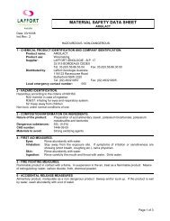
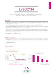
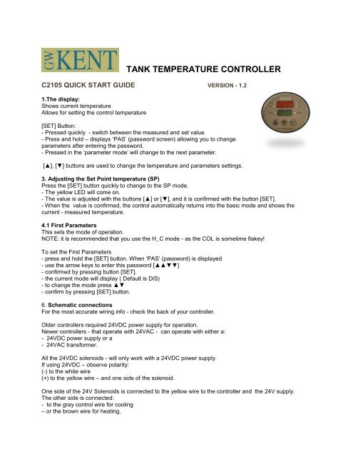
<strong>TANK</strong> <strong>TEMPERATURE</strong> <strong>CONTROLLER</strong>C2105 QUICK START GUIDE VERSION - 1.21.The display:Shows current temperatureAllows for setting the control temperature[SET] Button:- Pressed quickly - switch between the measured and set value.- Press and hold – displays ‘PAS’ (password screen) allowing you to changeparameters after entering the password.- Pressed in the ‘parameter mode’ will change to the next parameter.[▲], [▼] buttons are used to change the temperature and parameters settings.3. Adjusting the Set Point temperature (SP)Press the [SET] button quickly to change to the SP mode.- The yellow LED will come on.- The value is adjusted with the buttons [▲] or [▼], and it is confirmed with the button [SET].- When the value is confirmed, the control automatically returns into the basic mode and shows thecurrent - measured temperature.4.1 First ParametersThis sets the mode of operation.NOTE: it is recommended that you use the H_C mode - as the COL is sometime flakey!To set the First Parameters- press and hold the [SET] button. When ‘PAS’ (password) is displayed- use the arrow keys to enter this password [▲▲▼▼]- confirmed by pressing button [SET].- the current mode will display ( Default is DiS)- to change the mode press ▲▼- confirm by pressing [SET] button.6. Schematic connectionsFor the most accurate wiring info - check the back of your controller.Older controllers required 24VDC power supply for operation.Newer controllers - that operate with 24VAC - can operate with either a:- 24VDC power supply or a- 24VAC transformer.All the 24VDC solenoids - will only work with a 24VDC power supply.If using 24VDC – observe polarity:(-) to the white wire(+) to the yellow wire – and one side of the solenoid.One side of the 24V Solenoids is connected to the yellow wire to the controller and the 24V supply.The other side is connected:- to the gray control wire for cooling– or the brown wire for heating.
C2105 ManualInstructions for using <strong>GW</strong><strong>Kent</strong>’s individual tank temperature controller.DescriptionA microprocessor system for measuring and controlling temperature.Two-stage (cooling and/or heating) controlThree levels of password protected parameters -– to prevent accidental changes.Designed for moist humid environments.Alarm state indicatorRS485 network compatibility1. The display:Shows current temperatureAllows for setting the desired temperatureDisplays parameters and allows parameter changesLEDs shows the control status:Cooling - red LED is onHeating - red LED is onSet SP - adjusts the set temperatureUnits C/F – Celsius/ FahrenheitAlarm - flashes redButtons: [SET]Press quickly - switch between the measured and set value.Press and hold – displays ‘PAS’ (password screen) allowing you tochange parameters - after entering the password.Pressed in the ‘parameter mode’ will change to the next parameter.[▲], [▼] are used to change the set temperature and parameters settings.
The following abbreviations are used:- PV - Process Value - measured, actual temperature- SP - Set Point - the desired set temperature- HsH – Hysteresis Heating, temperature range within which output 1 does not changeits status,- HsC – Hysteresis Cooling, temperature range within which output 2 does not changeits status,- dbd - dead zone, temperature range symmetrically around the set point SP, withinwhich neither the cooling output nor the heating output change their status- ALU - high temperature value Indicator light would be flashed when PV temperature isover ALU value.- ALd lower temperature value Indicator light would be flashed when PV temperature isunder ALU value.- diS temperature display only, both outputs disabled- HEA heating control at output 1- C0L cooling control at output 1- H_C heating control at output 1 and cooling at output 2- OFF stand-by mode, both outputs disabled2. ModesThe controller has the following modes:- H_C - Heating and cooling control ( 1 heating output, 1 cooling output,)- HEA - Only heating is controlled (1 heating output, cooling output is disabled,)- CoL - Only cooling control (1cooling output , heating output is disabled)- diS - Display of the currently measured temperature (both outputs disabled). *- OFF - Stand-by mode (no display of temperature, both outputs disabled)- Adjustment of the set temperature PV- Setup of parameters 1, 2 and 32.1 Basic Heating & Cooling Mode - (three point control)Temperature control consists of an output for switching on the heating and an outputfor switching on the cooling. They are switched in according to the set controlparameters. The heating output is switched on (red light is on) (the valve is opened, theheater is switched on...), when the measured (actual) temperature PV is lower than thevalue of SP-½ dbd-HsH, and it is switched off, when the measured temperatureincreases above the value SP1/2 dbd. The cooling output is switched on (green light ison) (the valve is opened), when the measured temperature PV is higher than the valueSP+½ dbd+HsC, and it is switched off, when the measured temperature falls below thevalue SP÷½dbd.
2.2 Basic Heating Mode - (two-point control)If parameters HEA is chosen, the control changes to two-point control and performsonly the Function of the heating control. Heating output is switched on (red light is on),when the measured temperature PV is lower than the value SP-½ HsH, and it isswitched off, when the measured temperature PV increases above the value SP+1/2HSH.2,3 Basic Cooling mode ( two-point control)If parameters CoL is chosen, the control changes to two-point control and performs onlythe function of the cooling control. The cooling output is switched on (red light is on),when the measured temperature PV is higher than the value SP+1/2H5C, and it isswitched off, when the measured temperature PV falls below the value SP-1/zHsC.
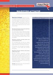
2.4. TroubleshootingError codes :-Er.S error sensor-Er.P error parametersIn the case of error sensor the controller automatically switches to the ‘safe mode’. Theheating and cooling the outputs change to the status, which is preset in the parameter‘safe mode’ SAF.Our replacement sensors have a different color code - than what was shipped withearlier units.When installing a new sensor to an old box – this is the color code.NewOldGround - Black - YellowDQ - Blue - Green+VDD - Brown - Red3. Adjusting the Set Point temperature (SP)Press the [SET] button quickly to change to the SP mode. The yellow LED will come on.The value is adjusted with the buttons [▲] or [▼], and it is confirmed with the button[SET]. When the entered value is confirmed, the control automatically returns into thebasic mode and shows the current measured temperature.If the selected change is NOT confirmed by pressing the button [SET] within 30seconds, the value of the set temperature SP (before changing) is preserved, and thecontrol returns into the basic mode - display of the current -- measured temperature.4. Control parametersWARNING:Changing of parameters is permitted only by adequately trained personnel.Incorrect control parameters - disable the functioning of the control.4.1 First ParametersThis parameter sets the mode of operation.NOTE: it is recommended that you use the H_C mode - as the COL is sometime flakey!To set the First Parameters- press and hold the [SET] button. When ‘PAS’ (password) is displayed- use the arrow keys to enter: [▲▲▼▼]- confirmed by pressing button [SET].- this will show the current mode ( Default is DiS)- to change the mode press ▲▼- confirm by pressing [SET] button.
OFFstand—by, both outputs inactiveHEAheating control at output 1 onlyCOLCooling control at output 2 onlyH_Cheating control at output 1 and cooling control atoutput 2 -DiSDisplay of temperature only, both outputsdisabled4.2 Second ParametersThese parameters define the values of heating hysteresis, cooling hysteresis; and thedead zones.To set the Second Parameters- press and hold the [SET] button. When ‘PAS’ (password) is displayed- use the arrow keys to enter: [▲▼▲▼]- confirmed by pressing button [SET]. The display will then show the first parameter- select the desired parameter by pressing ▲▼- and confirm by pressing [SET] button- this will show the set value- to change the value press ▲▼- confirm by pressing [SET] button.Parameters are:Abv. Parameter Range Default DescriptionHSHHeatinghysteresis0.1...20after 0.11 heating hysteresis,temperature range within which theheating output does not change its
status, heat,HSCCoolinghysteresis0.1… 20 after0.11 Cooling hysteresis,temperature range within which thecooling output: does not change itsstatus, cool.dbd Dead zone 0.1… 20 after0.1dead zone, temperature rangesymmetrically around t[e set valuePV, within which neither the coolingoutput not the heating outputchange their status.ALUHigh temperatureAlarm Point-9.9”99.9°CAfter 0.199.9˚Chigh temperature value indicatorlight would be flashed when PVtemperature is over the ALU value.ALdLow temperatureAlarm Point.-9.9”.’99.9°CAfter 0.114-211°FAfter 0.l-9.9°Clower temperature value indicatorlight would be flashed when PVtemperature is under ALU value.4.3 Third ParametersTo set the Third Parameters- press and hold the [SET] button. When ‘PAS’ (password) is displayed- use the arrow keys to enter: [▲▲▼▼▼]- confirmed by pressing button [SET]. The display will then show the first parameter- select the desired parameter by pressing ▲▼- and confirm by pressing [SET] button- this will show the set value- to change the value press ▲▼- confirm by pressing [SET] button.Parameters are:Abv. Parameter Range Default Description
TPU.Option ofmeasure unit oftemperature C/FCELFAHCELMeasure unit degree Celsius orFahrenheit.FIL Input Filter 0 to 60vz5 vzTime constant of input signal filter.SAF Safe ModenoACoLHEAnoAselection of mode in case of errornoA both outputs disabledCoL cooling output enabledHEA. .heating output enabledcoACommunicationAddress1 to 9991 Controller addresstStReset,Test,CorrectionInIEECorEndInIInI - Resetting parameters to presetvaluesEE - eprom testCor - temperature adjustEnd - exit by entering parametersWhen tSt is displayed, select the desired option by pressing ▲▼and confirm it bypressing [SET] button.Inl - resets all the parameters to the initial, preset values.EE - tests eprom. After the test the display shows:EGd - eprom functioning normallyBad - eprom corrupt5. Technical data of the controller:Display of value: -9.9°C to 99.9°C or 14.1211FResolution: 0.1°C (100°F IS 0.1°F ;Over 100°F is 1°F)Deviation: max ± 0.5°C(±D.99°F)Consumption:
6. Schematic connectionsFor the most accurate wiring info - check the back of your controller.Older controllers required 24VDC power supply for operation.Newer controllers - that operate with 24VAC - they can operate with either a:- 24VDC power supply or a- 24VAC transformer.All the 24VDC solenoids - will only work with a 24VDC power supply.If using 24VDC – observe polarity:(-) to the white wire(+) to the yellow wire – and one side of the solenoid.One side of the 24V Solenoids is connected to the yellow wire to the controller and the 24Vsupply.The other side is connected:- to the gray control wire for cooling– or the brown wire for heating.