Wire Harness Installation Instructions - Painless Wiring
Wire Harness Installation Instructions - Painless Wiring
Wire Harness Installation Instructions - Painless Wiring
You also want an ePaper? Increase the reach of your titles
YUMPU automatically turns print PDFs into web optimized ePapers that Google loves.
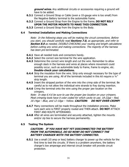
ground wires. Any additional circuits or accessories requiring a ground willhave to be added.6.3.1 Connect a Ground Strap or Cable (even a 10-gauge wire is too small) fromthe Negative Battery terminal to the automobile frame.6.3.2 Connect a Ground Strap from the Engine to the frame. DO NOT RELYUPON THE MOTOR MOUNTS TO MAKE THIS CONNECTION.6.3.3 Connect a Ground Strap from the Engine to the Body.6.4 Terminal <strong>Installation</strong> and Making ConnectionsNote: In the following steps you will be making the circuit connections. Beforeyou start, you should carefully read Sections 7.0, as appropriate, and refer toSection 8.0 as needed, DOUBLE-CHECKING your routing and length calculationsbefore cutting any wires and making connections. The majority of the harnesshas been pre-terminated.6.4.1 Have all needed tools and connectors handy.6.4.2 Select the correct size terminal for the wire application.6.4.3 Determine the correct wire length and cut the wire. Remember to allowenough slack in the harness and wires at places where movement couldpossibly occur, such as automobile body to frame, frame to engine, etc.Double-check your calculations.6.4.4 Strip the insulation from the wire. Strip only enough necessary for the type ofterminal you are using. All of the terminals included in this kit require a ¼”strip length.6.4.5 Insert the stripped portion of the wire into the crimp side of the terminal. Becareful as to not allow the individual wire strands to fray during insertion.6.4.6 Crimp the terminal onto the wire using the proper jaw location on thecrimpers.Note: In step 6.4.6 be sure to use the proper jaw location on your crimpers.Most crimping tools have it color coded for which cavity to use. 18-22ga – Red,16-14ga – Blue, and 12-10ga – Yellow. CAUTION: DO NOT OVER-CRIMP!6.4.7 Many connections will be made throughout the installation process. Makesure each wire is FIRST properly routed and THEN attach. DO NOT ATTACHFIRST AND ROUTE AFTERWARD.6.4.8 After all wires are terminated and securely attached, tighten the mountsand/or zip ties to secure the harness permanently.6.5 Testing The SystemCAUTION: IF YOU HAVE NOT YET DISCONNECTED THE BATTERYFROM THE AUTOMOBILE, DO SO NOW! DO NOT CONNECT THEBATTERY CHARGER WITH THE BATTERY CONNECTED.6.5.1 Use a small (10 amp or less) battery charger to power up the vehicle for thefirst time to test the circuits. If there is a problem anywhere, the batterycharger's low amperage and internal circuit breaker will provide circuitprotection.16


