
You also want an ePaper? Increase the reach of your titles
YUMPU automatically turns print PDFs into web optimized ePapers that Google loves.
NOTESPublication: SHL/<strong>SHT</strong>-0701112M-B <strong>Companies</strong>, <strong>Inc</strong>. Copyright 2011
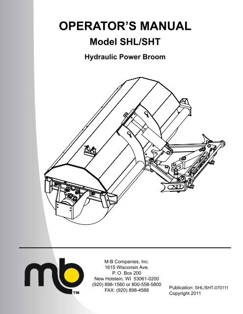
generalThe SHL/<strong>SHT</strong> Model brooms are hydraulically-driven. The <strong>SHT</strong> model fortractors uses a hydraulic cylinder for lift in place of the anchor used on theSHL model for loaders/skid steers.operator’s manualYou must read, understand and comply with all the safety and operatinginstructions in this manual before attempting to set-up and operate yourpower broom.Failure to comply with the safety and operating instructions can result inloss of machine control, serious personal injury to you and/or bystanders,and risk of equipment and property damage.identification numbersWhen contacting your authorized dealer for information, replacementparts or service, you MUST have the model and serial number of yourunit.Record the serial number in the space provided. The serial numberplate/decal can be found in the location shown in Figure 1.introductionModel Name/Number:Date Purchased: Serial #:Figure 1.Publication: SHL/<strong>SHT</strong>-070111M-B <strong>Companies</strong>, <strong>Inc</strong>. Copyright 20113
This Page Intentionally BlankPublication: SHL/<strong>SHT</strong>-0701114M-B <strong>Companies</strong>, <strong>Inc</strong>. Copyright 2011
safety alertsSignal words and alert symbols notify of important safety precautions.safetyDANGER!Indicates a hazardous situation which,if not avoided, will result in seriousinjury or death.WARNING!Indicates a hazardous situation which,if not avoided, could result in seriousinjury or death.CAUTION!Indicates a hazardous situation orunsafe practice which, if not avoided,could result in minor or moderate injuryor property damage.safety decalsAlthough reading this manual and the safety instructions it contains willprovide you with the necessary basic knowledge to operate this equipmentsafely and effectively, we have placed several safety labels on theunit to remind you of this important information while you are operatingyour unit.All DANGER, WARNING, CAUTION, and instructional messages on yourunit should be carefully read and obeyed. Bodily injury can result whenthese instructions are not followed. The information is for your safety andit is important.These labels will act as a constant visual reminder to you, and others whomay use the equipment, to follow the safety instructions necessary forsafe, effective operation.If any of these labels are lost or damaged, replace them at once. See youlocal dealer for replacements.PRE-START GUIDELINES• Install any covers or guards which may have been removed for shippingpurposes.• Before starting equipment, walk around equipment, making a visualinspection that all safety devices are properly installed and secured.• Check that all hardware, fasteners, hydraulic fittings, etc. are in goodcondition and properly fastened. Replace any fatigued or damageditems with proper replacements.• Personnel who are not required to be in the work area should be keptaway. Never start the equipment unless you are absolutely certainthat everyone in the area is clear of the machine and aware it is beingstarted.• Follow the manufacturer’s recommended start-up procedure.operation guidelinesRead, understand and follow all instructions in the manual and on the unitbefore starting.• To avoid serious injury or death, do not modify equipment. Any modificationsmade to equipment can be dangerous and can void equipmentwarranty.• Never defeat a safety device to make a task easier.• Always wear proper apparel when operating equipment; safetyglasses, face shield or goggles, ear protection, and dust mask. Tie hairback. Never wear loose clothing or jewelry that could get caught inmoving parts.• Never operate equipment with covers or guards removed. Rotatingparts can cause severe injury. Keep hands, feet, hair, jewelry andclothing away from all moving parts.• Only allow responsible adults who are familiar with the instructions, tooperate the unit (local regulations can restrict operator age).• Clear the area of objects such as rocks, toys, wire, etc., which could bepicked up and thrown.• Be aware of surroundings. Be sure the area is clear of other people,bystanders or pets. Stop unit if anyone enters the area.• Always look down and behind before and while traveling in reverse.Publication: SHL/<strong>SHT</strong>-110711M-B <strong>Companies</strong>, <strong>Inc</strong>. Copyright 20115
safety• Be aware of discharge direction and do not point discharge at anyone.Do not point the discharge at glass enclosures, automobiles, or windows.• Always stand clear of the discharge area when operating this unit.• Disengage all clutches and PTO’s before starting engine.• Never leave a running machine unattended. Always disengage theattachment and traction controls, lower the attachment, set the parkbrake, stop the engine and remove the ignition key before leaving themachine.• Operate only in daylight or good artificial light.• Never carry passengers.• Do not operate the unit while under the influence of drugs, alcohol orother medication.• Watch for traffic when operating near or crossing roadways.• Use extra care when loading or unloading the unit into a trailer or truck.• Keep in mind the operator is responsible for accidents occurring toother people or property.• Data indicates that operators, age 60 years and above, are involved ina large percentage of power equipment-related injuries. These operatorsshould evaluate their ability to operate the unit safely enough toprotect themselves and others from injury.• All operators should seek and obtain professional and practical instruction.• Protect eyes, face and head from objects that may be thrown from unit.Wear appropriate hearing protection.• Always wear substantial footwear and appropriate clothing. Wearfootwear that improves traction on slippery slopes. DO NOT wear longscarves or loose clothing that could become entangled in moving parts.• Abnormal Vibrations are a warning of trouble. Striking a foreign objectcan damage unit. Stop unit and engine. Wait for all moving parts tostop. Inspect unit and make any necessary repairs before restart.• Never place your hands or any part of your body or clothing inside ornear any moving part while unit is running.• Stop engine before: refueling, cleaning, making adjustments or removingthe attachment assembly.• Follow the drive unit manufacturer’s recommendations for wheelweights or counter weights.• Make any adjustments before operating unit.• Do not touch parts which may be hot from operation. Allow such partsto cool before attempting to service the unit.• Before using, always visually check that hardware is present, intactand secure. Replace worn or damaged parts.• Never operate the machine with damaged guards, or without safetyprotective devices in place.• Follow the manufacturer’s recommendations for towing weight restrictionsand procedures.• Original purchaser of this unit was instructed by the seller on safe andproper operation. If unit is to be used by someone other than originalpurchaser; loaned, rented or sold, ALWAYS provide this manual andany needed safety training before operation.• The Operator must understand the functions and parameters of all controlsand how to operate, as well as how to STOP in an Emergency.maintenance guidelines• Maintain or replace safety and instruction decals/labels as necessary.• Never run a unit in an enclosed area.• Keep nuts and bolts tight and keep equipment in good condition• Never tamper with safety devices. Check their proper operation regularlyand make necessary repairs if they are not functioning properly.• Keep unit free of debris and build-up. Clean up any oil spillage.• Never make adjustments or repairs with the engine running unlessspecified otherwise in the engine manufacture’s manual.• Components are subject to wear, damage, and deterioration. Frequentlycheck components and replace with the manufacturer’s recommendedparts, when necessary.• Check control operation frequently. Adjust and service as necessary.• Use only factory authorized parts when making repairs.• Always comply with factory specifications on all settings and adjustments.• Only authorized service locations should be utilized for major serviceand repair requirements.• Never attempt to make your own repairs on this unit unless you havebeen properly trained. Improper service procedures can result in hazardousoperation, equipment damage and voiding the manufacturer’warranty.• Stop engine on tractor and set parking brake before performing anyadjustments on the machinery.• Do not disassemble a pressurized system unless properly trained andequipped with adequate tooling.• Escaping hydraulic fluid under pressure can have sufficient force topenetrate the skin, causing serious injury. Before operation, be surethat all hydraulic connections are tight and hoses are not damaged.Relieve pressure in system before making adjustments.• Oils and fluids can be very hot under pressure. Use caution and allowthe system to cool before beginning maintenance work.• Never operate or pressurize one of these systems with worn or damagedcomponents. Replace hoses, fittings, valves or other componentswhich appear defective.• Never adjust pressurized systems beyond recommended levels toachieve higher operating pressures.• NEVER search for hydraulic leaks with only your hands. Use cardboardor a piece of wood.• For engine equipped models, follow specific engine manufacturer’srecommended service intervals for dirty/dusty environments.NOTE:All reference to left, right, front, or rear are given from theoperator position and facing forward.Publication: SHL/<strong>SHT</strong>-1107116M-B <strong>Companies</strong>, <strong>Inc</strong>. Copyright 2011
controls and featurescontrolsOperation of the SHL/<strong>SHT</strong> Power Broom is accomplished with theprime mover’s controls. Refer to the prime mover’s Operation/Owner’sManual.featuresRefer to the Setup and Adjustments instruction, Specifications andParts Lists within this manual for information on the SHL/<strong>SHT</strong> PowerBroom components and functions.Publication: SHL/<strong>SHT</strong>-070111M-B <strong>Companies</strong>, <strong>Inc</strong>. Copyright 20117
This Page Intentionally BlankPublication: SHL/<strong>SHT</strong>-0701118M-B <strong>Companies</strong>, <strong>Inc</strong>. Copyright 2011
setup and adjustmentssetupProper setup and leveling of your power broom will increase the life ofthe brush and produces more efficient movement of material. Visuallyinspect the adjustments on the broom before each operating sessionand measure the adjustments once every 10 hours.The following procedures must be followed in the prescribed sequencein order to be effective.levelingSee Figure 1.1. After the broom is mounted to the prime mover (tractor, skidsteer,loader), park the unit on a flat level surface; preferablyconcrete or asphalt.2. If mounted to a tractor (<strong>SHT</strong>), the frame is fixed and no movementis possible. See Figure 1.3. If mounting to a skid-steer (SHL), lower the arms all the waydown and tilt (rotate) the top of quick-attach all the way back untilbolt contact plate is vertical (at 90° to ground). See Figure 2.NOTE: Some brand skid steers may not allow top of Quik-Attachto be rotated back far enough to correctly position contactplate. This may not allow the swing arms to be properlyleveled because the supplied front-to-rear leveling bolts willnot be long enough. In this case, longer bolts (4") must besourced from a local supplier.4. If mounting to a loader (SHL), tilt the bucket cylinders all theway back until bolt contact plate is vertical. Lower the arms untilthe horizontal mounting shaft is 14.5" from the ground. If there isa way to set this location on the loader hydraulics, do so at thistime. See Figure 2.NOTE: Occasionally the horizontal mounting shaft is replaced bypins or bolts, based on mounting.5. Swing the broom so that it is horizontal and tighten the patternadjustment nuts all the way down. See Figures 1 and 2.Quik-Attach tilted back so that bolt contact plate is perpendicular(90°) to ground.Quik-Attach90°HorizontalMountingShaft14.5" forLoader Mounting90°GroundLeveling BoltsContact PlateFigure 2SwingArmsSHL ModelAnchor RodSwingFrameSwingCylinderLevel onSwing Arm<strong>SHT</strong> Model Lift CylinderPatternAdjustmentNutsHorizontalMountingShaftAdjustmentArmSwing ArmFront-to-Rear LevelingBolts and Jam Nuts (2)Jam NutBroom HeadSide-to-Side(Left-Right)Leveling BoltFigure 1Publication: SHL/<strong>SHT</strong>-070111M-B <strong>Companies</strong>, <strong>Inc</strong>. Copyright 20119
setup and adjustments6. Adjust the swing arms so they are level front-to-rear by adjustingthe bolts in or out on the back of the swing mounting frame.Adjust both bolts evenly to maintain an even load on the mountingframe and the arms. Check to see that the arms are level byplacing a level along one of the arms. Once the arms are level,tighten the jam nuts against the swing frame to lock the bolts inplace. See Figures 1 and 2.7. Adjust the broom head so it is level side-to-side by adjustingthe bolt in the adjustment arm on the top of the swing mountingframe. Adjust the bolt in (down) to lower the left side, and adjustit out (up) to raise the left side. Check for level on the broomhead by placing a level along the length of the hood. Once thebroom head is level, tighten the jam nut against the adjustmentarm to lock the bolt in place. See Figure 1.8. Recheck the level on the swing arms. If the arms are still level,continue to Pattern Adjustment. If not, perform the levelingprocess again.pattern adjustment1. After the broom has been leveled, the last adjustment is to setthe brush pattern (swept area).2. With the unit on a flat level surface, adjust the nuts on the end ofthe hydraulic lift cylinder (<strong>SHT</strong>) or actuator rod (SHL) so that thebroom contact patch is approximately 3" wide from front to rear.Loosening the nuts will lower the broom, creating more contact.See Figures 1 and 2.3. Once this adjustment is set, it can be confirmed by running theunit for about 30 seconds in the down position while stationary.Stop the broom and back the unit away. The ‘cleaned’ (contactpatch) should be 2"-4" wide for the entire length of the broom.See Figure 3.The level of the broom may create too heavy a brush pattern on eitherthe left or right side. In order to balance the pattern, the Side-to-Side(Left-Right) Leveling Bolt in the Adjustment Arm (Figure 1) must beadjusted to compensate for the lean. See Figure 4.Leveler bolt shouldbe adjusted outward,or up.Side-to-SideAdjustmentFigure 4Broom head may be either pitched down too far forward or up toofar backward on either side swing arm, giving us the impression of abowtie. The swing frame bolts must be adjusted either out or in, eitherseparately or together, to achieve a balanced pattern. See Figure 5.Front-to-RearAdjustmentLeveler bolt shouldbe adjusted inward,or down.Tilted Forward - Swingframe leveler bolts shouldbe adjusted outward.Tilted Backward - Swingframe leveler bolts shouldbe adjusted inward.Figure 5Once the broom has been properly adjusted, a short operation periodis recommended for break-in; approximately 15 minutes. After thisbreak-in period, repeat the leveling procedure to ensure that it is correct.Figure 3Publication: SHL/<strong>SHT</strong>-07011110M-B <strong>Companies</strong>, <strong>Inc</strong>. Copyright 2011
operationpre-startup checksIMPORTANT! You must read, understand and comply with all thesafety and operating instructions in this manual beforeattempting to set-up and operate your power broom.Failure to comply with the safety and operating instructionscan result in loss of machine control, seriouspersonal injury to you and/or bystanders, and risk ofequipment and property damage.1. Visually inspect equipment and hardware to ensure that all partsare secure and all hardware is tightened and secure.2. Check for oil leaks and loose hose connections.3. Inspect the broom adjustments to ensure that the broom is leveland that there is proper brush pattern. Refer to the SETUP ANDADJUSTMENT section.4. Inspect the bristle length to determine if replacement segmentsare needed.TRAVEL PROCEDUREFollow these instructions for extended travel (i.e. to and from thesweeping site):• Move the broom switch to the on/off position.• Move the lift toggle to the up position until the brush is in the fullyraised position.• Raise the support stands to the highest position and secure in place.• If equipped with the engine pallet system, be certain the engine forthe independent hydraulic system is set to the “STOP” position.operationIMPORTANT! The support stands should never be used for anythingother than as stationary storage stands to hold thebroom up while it is being stored.• Ensure the support stands are raised to the highest position andsecured in place.• Sweep at a speed that is appropriate for the conditions and location.• For heavy material such as gravel or stones, drive more slowly witha higher broom speed. For lighter material, drive faster with a lowerbroom speed.• It may be necessary to increase broom contact pattern under someconditions. If the surface being swept is uneven and causes thebroom to leave upswept patches, increase the pattern size to compensate.• If the material being swept is dried-on or difficult to remove, such asmud or ice, it may be necessary to drive extremely slow to allow thebroom to “scrub” the surface.Publication: SHL/<strong>SHT</strong>-070111M-B <strong>Companies</strong>, <strong>Inc</strong>. Copyright 201111
This Page Intentionally BlankPublication: SHL/<strong>SHT</strong>-07011112M-B <strong>Companies</strong>, <strong>Inc</strong>. Copyright 2011
maintenancemaintenance schedule• Check adjustments – every 10 hours• Grease bearings – after initial 10 hours, then every 200 - 300 hoursthereafter.• Grease pivot points – every 50 hoursEnd DiscMotor Mount PlateMotorBrush FrameMotor GuardNOTE:Grease points are noted with an applicable decal.NOTE: Maintenance pertaining to oil and oil filter only refers to theindependent hydraulic systems provided by M-B Co.• Check and refill oil level – every 50 hours• Replace oil filter – every 250 hours• Replace hydraulic oil – annually• Replace brush filler – as neededlubrication• Grease bearings and pivot points per the maintenance scheduleusing Chevron Ultra Duty II, Grade 2; or equivalent high-tempgrease.• There are minimum of (8) grease points on the unit; (4) at the horizontalswing arms, (2) at the vertical lift pivot points and (2) on thebrush end bearings.• Use Chevron Rykon MV, Dexron-III/Mercon ATF or equivalent forM-B supplied independent hydraulic systems. If the oil is suppliedby the prime mover, use the prime mover manufacturer’s recommendedfluid.Figure 13. Remove (3) or (4) 5/16-18 x 3/4" capscrews, lock washers andend disc (wafer retainer plate) from one end of core. Retain enddisc and mounting hardware. See Figures 2 and 3.4. Slide spent brush wafers and spacers off core and discard.Brush Frame BearingHub End Discfiller replacementCore Removal1. Lower broom until brush contacts the ground via hydraulic liftcylinder (HT) or mechanical head anchor (HL).NOTE: Steps 2 and 3 apply to each brush drive motor, whetherbroom is single or dual motor drive.2. Remove (2) 1/2-13 x 1-1/2" capscrews, flat washers, lock nutsand motor guard from brush frame. Retain guard and mountinghardware. See Figure 1.3. Remove (2) 1/2-13 x 1" capscrews, flat washers, lock nuts andmotor mount plate from brush frame. Slide motor out of matingsplined hub. Let motor hang on hoses. Retain mounting hardware.See Figure 1.4. Remove (2) 1/2-13 x 2" bolts, flat washers and lock nuts attachingcore support bearing to bottom of brush frame at each endof broom. See Figure 2.5. Slide core out the front of broom.Brush Removal1. Remove end bearing from hub on one end of core.2. Remove (3) 1/2-13 x 1" capscrews, lock washers and splinedhub from one end of core. Retain hub and mounting hardware.See Figures 2 and 3.HubCoreFigure 2Publication: SHL/<strong>SHT</strong>-070111M-B <strong>Companies</strong>, <strong>Inc</strong>. Copyright 201113
Brush Installation1. Stand core in upright position and begin filling by sliding a polybrush wafer and then a spacer down the full length of the core.a. Note the location of the drive pin on the inside ring of eachbrush wafer. Position each wafer so its drive pin is positionedbetween the stop flanges. Rotate each subsequent waferbefore installing so the position of its pin is staggered on thecore by one stop flange. See Figure 3.IMPORTANT! Proper wafer and spacer position must be followed toensure proper balance on the core.maintenanceStop FlangeWaferDrive PinCoreWaferDrive PinStopFlangeCoreFigure 4Figure 3NOTE: Brush surface contact during initial operation will set all waferdrive pins up against the core stop flanges. See Figure 4.b. The circular spacers have unconnected, overlapped ends.Position the overlap of the first spacer between the stopflanges, rotated one flange ahead of the drive pin location ofthe immediately preceding brush wafer. All subsequent spacersmust follow the same staggered placement pattern.3. Continue stacking the core in a wafer-spacer, wafer-spacerconfiguration until it is full, ending with a poly brush wafer.NOTE: Always start and finish with a poly wafer. The last wafershould actually extend beyond the end of the core (Minimum1/2") so the end disc compresses the spacers onto the corewhen tightened.4. Install end disc on core with original hardware. See Figure 2.5. Install splined hub on core with original hardware. See Figure 2.6. Install end bearing on hub. See Figure 2.Core Installation1. Position refilled core in front of the broom head. Lift the broomhigh enough so that core clears the hood and the brush can berolled/pushed back into its original position. Once in place, lowerbroom head down onto support bearing at each end of core.2. Attach pillow block bearings to bottom of brush frame at eachend of broom with original hardware. See Figure 2.NOTE: Steps 3 through 5 apply to each brush drive motor, whetherbroom is single or dual motor drive.Apply grease to hub splines before installing hydraulicmotor(s).3. Slide motor shaft into mating splined hub.4. Install motor mount plate on brush frame using original hardware.See Figure 1.5. Install motor guard on brush frame with original hardware. SeeFigure 1.6. Before placing machine back into service, adjust and test forproper amount of brush pattern. Excessive and/or misalignedpattern can cause brush failure or premature wear. Refer tothe Setup and Adjustments section of the manual for patternadjustment.Publication: SHL/<strong>SHT</strong>-07011114M-B <strong>Companies</strong>, <strong>Inc</strong>. Copyright 2011
storagestorage• Always store the broom in a supported position, on its includedstands, with the brush off the ground. If the bristles are stored ina deformed position for extended periods of time the broom willbecome severely out of balance.• Store the broom in a location out of the sun and weather to preventpremature failure of plastic bristles. Bristles can become brittle whensubjected to sunlight or repeated temperature changes.• Disconnect all electrical connections between the broom and primemover (loader/tractor) for extended storage to prevent battery drain.• Properly clean the unit before storage and remove dirt, debris, salt,etc. to extend paint life.• If the unit is power-washed, all lubrication points should be greasedbefore storage.troubleshootingTrouble Possible Cause RemedyBroom does not rotate. 1. No hydraulic pressure/flow.2. Hoses disconnected.3. Hoses bent or kinked.4. Pressure relieving too low.5. Electric valve not functioning.1. Check tractor operation.2. Connect hoses and fittings.3. Remove sharp bends and kinks.4. Adjust relief valve.5. Check electrical connections.Broom rotates in wrong direction. 1. Hoses installed incorrectly. 1. Switch hydraulic hose connectionsBristles wearing unevenly. 1. Swing arms not level.2. Broom head not level.3. Pattern adjustment not set.4. Tires on prime mover at different pressuresor of different sizes.1. Adjust using bolts on rear of frame.2. Adjust using leveling bolt on top of frame.3. Adjust on head anchor/lift cylinder.4. Check tire pressure, sizes and rating. Adjustand/or correct as necessary.Brushes wear very quickly. 1. Brush pattern too wide. 1. Adjust brush pattern to be 2-4” wide. Referto the Setup and Adjustments section ofthis manual.Broom bounces during sweeping. 1. Travel speed too fast and/or brush speedtoo slow.Broom sweeping poorly. 1. Material is ‘caked-on’ or frozen.2. Uneven sweeping surface.3. Material is too heavy.4. Broom rotating too slowly.5. Prime mover moving too fast.6. Pattern adjustment incorrectly set.Broom does not lift or angle. 1. No/Low hydraulic pressure/flow.2. Electric valve not functioning.3. System backpressureHydraulic pump making noise. 1. Pump intake blocked.2. Shaft seal leaking.1. Adjust to find correct ground and brushspeed for surface.1. Slow down and ‘scrub’ surface.2. <strong>Inc</strong>rease pattern to compensate.3. Slow down prime mover speed.4. <strong>Inc</strong>rease engine speed.5. Slow down prime mover speed.6. Adjust at head anchor.1. Check prime mover operation.Check hydraulic oil level. Refer to Maintenancesection of this manual for hydraulicsystem requirements.2. Check electrical connections.3. Check prime mover instructional manual.1. Check inlet lines for obstructions.2. Check and repair as necessary.Publication: SHL/<strong>SHT</strong>-070111M-B <strong>Companies</strong>, <strong>Inc</strong>. Copyright 201115
This Page Intentionally BlankPublication: SHL/<strong>SHT</strong>-07011116M-B <strong>Companies</strong>, <strong>Inc</strong>. Copyright 2011
specificationsModel: SHL (Loader) <strong>SHT</strong> (Tractor)Brush Diameter 25"Brush Length: 4' (48"), 5' (60"), 6' (72"), 7' (84") 5' (60"), 6' (72"), 7' (84")Brush DriveMotor:Single hydraulic motor (standard) for prime mover with 12 to 20 GPM.Optional low flow hydraulic motor for prime mover with 8 to 11 GPM.(Note: Hoses are provided from broom motor to bulkhead fittings. Customer to provide hoses and couplers to connectloader/tractor hydraulics to bulkhead and lift cylinder. Optional hose kit available. Does not include hydraulic valve(s) onprime mover. Brush on/off with tractor/loader valve.)Brush Speed200 RPM MaximumBrush Angle:Maximum 30° left/rightShipping Weight:4' (48") 800 NA5' (60") 850 8506' (72") 900 8867' (84") 1000 950Brush Filament:Poly (polypropylene), Wire (steel) or Combo (Poly/Wire)Swing MethodManualHydraulic(Hydraulic cylinder only. Customer must provide hydraulic hoses, coupler and valve to swing cylinder.)Electric/Hydraulic SwingElectric/Hydraulic Swing and LiftMounting:Options:Needed to complete hydraulic swing for skid steer. (Valveand control box actuate the swing cylinder.)Electric/Hydraulic Swing with ReverseRequired if remotes are not available for lift and swing functions.(Valve and control box actuate the swing cylinder.)Electric/Hydraulic Swing and Lift with ReverseReverse valve electronically changes direction of broom rotation.No Mounting by <strong>MB</strong> (Provided by customer.)Pin and/or quick-attach mountings for most popular applications.Some loaders with quick-attach buckets will requirecustomer to provide female quick-attach. Consult M-B.Standard Skid Steer Quick Coupler SAE J2513.Agricultural tractor front mount frame with tank mountingcapabilities.Quick Coupler Mounting for loaders. (Hook and Pin)Mounting Frame with Pin-on ears. Customer may be requiredto provide dimensions (Pin only).Custom Mount Design (Applies to mounts not previously designed by <strong>MB</strong>.)Independent Hydraulic system (IHS)Required if tractor/loader auxiliary hydraulic system cannot supply 8 GPM @ 2,000 psi. <strong>Inc</strong>ludes hydraulic pump, reliefvalve, hydraulic reservoir and hoses to broom. (Minimum of 25Hp on tractor required.)Hose Kit and CouplersBroom HoodDirt Deflector (Hood)45 Gallon Sprinkler System (Application specific, requires evaluation.)Sight/Guide IndicatorsPublication: SHL/<strong>SHT</strong>-070111M-B <strong>Companies</strong>, <strong>Inc</strong>. Copyright 201117
service partsPart NumberDescription907-63444 Refill Kit, 25" x 4', Wafer, Poly907-92090 Refill Kit, 25" x 4', Wafer, Alternating Poly/Wire907-92091 Refill Kit, 25" x 4', Wafer, Wire907-90817 Refill Kit, 25" x 4', Wafer, Poly/Wire Combo907-46674 Refill Kit, 25" x 5', Wafer, Poly907-92092 Refill Kit, 25" x 5', Wafer, Alternating Poly/Wire907-46676 Refill Kit, 25" x 5', Wafer, Wire907-46675 Refill Kit, 25" x 5', Wafer, Poly/Wire Combo907-46671 Refill Kit, 25" x 6', Wafer, Poly907-92093 Refill Kit, 25" x 6', Wafer, Alternating Poly/Wire907-90592 Refill Kit, 25" x 6', Wafer, Wire907-64664 Refill Kit, 25" x 6', Wafer, Poly/Wire ComboPart NumberDescription410-94050 Storage Stand380-76379 Clevis Pin, Storage Stand380-84739 Hair Clip, Clevis Pin390-160105 Guide Stick, 1/2" x 26"401-160790 Bracket, Guide Stick109-131128 Paint, Spray, <strong>MB</strong> Yellow249-92003 Paint, Spray, Black249-92005 Primer, Spray907-63472 Refill Kit, 25" x 7', Wafer, Poly907-92094 Refill Kit, 25" x 7', Wafer, Alternating Poly/Wire907-63473 Refill Kit, 25" x 7', Wafer, Wire907-63474 Refill Kit, 25" x 7', Wafer, Poly/Wire Combo401-132066 Guard, Motor201-75209 Hydraulic Motor, Standard Flow201-75649 Hydraulic Motor, Low Flow201-92028 Shaft, Hydraulic Motor(201-75209 and 201-75649)201-92039 Seal Kit, Hydraulic Motor(201-75209 and 201-75649)600-68509 Bearing, Core Hub Support410-93199 Hub, Splined, Core Support402-93754 End Disc, Core203-92074 Cylinder, Swing203-50013 Seal Kit, Swing Cylinder100-132340 Pin, Swing203-72275 Cylinder, Lift203-92006 Seal Kit, Lift Cylinder200-92309 Seal Kit, Hydraulic PTO Pump(200-92110 and 200-92218)200-50033 Seal Kit, Hydraulic PTO Pump (200-138105)Please have your serial number (S/N) ready when contacting M-B Co. or an Authorized Dealer for replacement parts or service information.M-B Co.website: www.m-bco.com1615 Wisconsin Ave. email: sales@m-bco.comP.O. Box 200 Phone: 800-558-5800 or 920-898-4203New Holstein, WI 53061-0200FAX:Main 920-898-4588Attachments 920-898-1085Brush Dept. 920-898-1082Publication: SHL/<strong>SHT</strong>-070111M-B <strong>Companies</strong>, <strong>Inc</strong>. Copyright 201119
4111 or 12732510689 6M-B <strong>Companies</strong>, <strong>Inc</strong>. Copyright 2011Publication: SHL/<strong>SHT</strong>-070111
SHL/<strong>SHT</strong> DecalsItem Description Part NumberDecal Sheet 390-117958 (<strong>Inc</strong>ludes items 1 - 11)1 • Decal, WARNING, Flying Debris 390-1692222 • Decal, Brush Pattern 390-1183543 • Decal, M-B Brush Refills 390-1183554 • Decal, DANGER, No Riders 390-1183495 • Decal, <strong>MB</strong> Logo, Black, Large 390-1178986 • Decal, Grease 390-1183567 • Decal, WARNING, High Pressure Fluid 390-1692218 • Decal, DANGER, Pinch Point 390-1183539 • Decal, WARNING, Moving Part/Guards 390-11835210 • Decal, <strong>MB</strong> Logo, Black, Medium 390-11789711 • Decal, CAUTION, Read Operator’s Manual 390-118351 (M-B Co.)12 Decal, CAUTION, Read Operator’s Manual 390-151987 (Non-M-B Co.)M-B <strong>Companies</strong>, <strong>Inc</strong>. Copyright 2011Publication: SHL/<strong>SHT</strong>-070111
HYDRAULIC MOTORStandard Displacement (201-75209)Low Displacement (201-75649)M-B <strong>Companies</strong>, <strong>Inc</strong>. Copyright 2011Publication: SHL/<strong>SHT</strong>-070111
HYDRAULIC MOTORStandard Displacement (201-75209)Low Displacement (201-75649)Item Description Part Number QtyKit, Seal 201-92039 1 (<strong>Inc</strong>ludes items 1 - 12)1 • Seal, Dust2 • Seal, Housing3 • Shim, Metal Backup4 • Seal, High Pressure5 • Shim, Metal Backup6 • Seal, Polyamide7 • Seal, Shaft8 • Seal, Rear Housing9 • Seals, Body (2)10 • Seal, End Cover11 • Seal Carrier12 • Washer, Thrust13 Bearing, Front Thrust 201-169461 114 Bearing, Housing Front (Available in Item 15, Housing Kit, P/N 201-92022)15 Kit, Housing 201-92022 1 (<strong>Inc</strong>ludes Items 14 & 16)16 Bearing, Housing Rear (Available in Item 15, Housing Kit, P/N 201-92022)17 Bearing, Rear Thrust 201-92027 118 Kit, Drive Link (<strong>Inc</strong>ludes Item 20) 201-92029 1 (Standard Displacement Motor P/N 201-75209)201-169461 1 (Low Displacement Motor P/N 201-75649)19 Plate, Manifold 201-92031 120 Spacer, Drive Link (Available in Item 18, Drive Link Kit, P/N 201-92029)21 Rotor, Roller Stator 201-92032 1 (Standard Displacement Motor P/N 201-75209)201-169459 1 (Low Displacement Motor P/N 201-75649)22 Plate, Balance (<strong>Inc</strong>ludes Item 23) 201-92034 123 Balls, 3/16" Steel 201-92033 324 End Cover 201-92035 126 Kit, Bolt 201-92036 1 (Standard Displacement Motor P/N 201-75209)201-169460 1 (Low Displacement Motor P/N 201-75649)27 Shaft, Splined 201-92028 1M-B <strong>Companies</strong>, <strong>Inc</strong>. Copyright 2011Publication: SHL/<strong>SHT</strong>-070111
HYDRAULIC MOTOR PI444002 Rev. 11.10Standard Displacement (201-75209)Low Displacement (201-75649)SERVICE INSTRUCTIONS FOR THE RE [500 & 501] SERIES MOTORSFor Use With Seal Kits: 500444001 & 500444002dimensions: mm [in]NOTE: IN DECE<strong>MB</strong>ER 2006, THE 500 SERIES INCORPORATED A DESIGN CHANGE. THIS SET OF INSTRUCTIONS WILLAID IN THE DISASSE<strong>MB</strong>LY AND ASSE<strong>MB</strong>LY FOR BOTH DESIGNS. MID 2010 A DESIGN CHANGE WAS IMPLEMENTEDON WHEEL MOUNTS TO REMOVE THE EXTERNAL DUST SEAL AND REPLACE IT WITH AN INTERNAL EXCLUDERSEAL. PLEASE REFER TO THE EXPLODED VIEW DRAWING ON PAGE 3 TO DETERMINE WHICH DESIGN IS BEING RE-PAIRED AND THEN FOLLOW THE APPROPRIATE INSTRUCTIONS FOR THAT DESIGN.A)B)C)D)Motor Section Disassembly (Same Instructions For Both Designs)Remove all shaft related components from shaft (27) (i.e. keys, wire rings, nuts). To aid in reassembly of the motor, make a "V"shaped set of lines from the endcover (24) to the housing using either paint or a marker. With shaft facing down, secure motor invise by clamping on to housing (15).Loosen and remove seven bolts (26) holding motor assembly together. Remove endcover (24) and endcover seal (10). Discardseal. Remove balance plate (22) taking care not to drop the three steel balls (23) located in the three holes in the balance plate(22). Remove rotor assembly (21), manifold (19), drive link spacer (20) (NOTE: Some motors do not use spacer), drive link (18)and thrust bearing (17). Remove body seals (9) from rotor assembly (21) and housing seal (8) from housing (15) and discardseals. (NOTE: Compare old housing seal (8) to the two housing seals included in kit to determine which one to use.) Gently tapshaft (27) upward from housing (15) and remove through rear of housing and lay aside.Housing/Shaft Disassembly And Assembly (Design That Utilizes A Seal Carrier (11))Remove housing (15) from vise and turn over. Pry dust seal (1) from housing. Push the seal carrier (11), thrust washer (12) andthrust bearing (13) down until they make contact with the roller bearing (14) located in the housing bore.Remove wire ring (2), steel backup shim (3) and high pressure seal (4) from inner bore groove with a small screwdriver. Lift sealcarrier (11), thrust washer (12) and thrust bearing (13) from the housing bore. Using a small screwdriver, carefully pry shaft seal(7), backup seal (6), and metal backup shim (5) from seal carrier (11) and discard. Lay seal carrier (11), thrust washer (12) andthrust bearing (13) aside. (NOTE: If a new thrust washer (12) and seal carrier (11) is included in kit, old items may be discarded).At this point, all parts should be cleaned in an oil-base solvent and dried using compressed air (For safety, observe all OSHAsafety guidelines). All new seals should be lightly coated in clean oil prior to installation.E)F)G)H)I)Place shaft (27) on a clean flat surface with output end facing up. Place thrust bearing (13) (NOTE: If thrust bearing has integralwasher, make sure washer surface faces down.) Then thrust washer (12) on shaft (See Technical Bulletin PI444004 to determinecorrect thrust washer to use). Lightly coat seal area of shaft with clean oil and place plastic installation sleeve with shaft seal (7)down onto shaft covering all splines, keyways and wire ring grooves. Slide shaft seal (7) down onto shaft (27) making sure thatlip on seal faces down (See Figure 1 for correct seal orientation) until it contacts thrust washer (12). Remove plastic installationsleeve. Carefully install the backup seal (6) onto the shaft (27) with the flat side up and the seal lip facing the shaft seal (7). Placethe metal backup shim (5) onto the shaft and against the backup seal (6). Place the seal carrier (11) onto the shaft (large enddown) and carefully press the seal carrier (11) down onto the seal assembly using an arbor press and sleeve to compress the sealinto the carrier.With pilot side facing up, place housing (15) on spacers to raise housing approximately 6 [.25] above work surface (NOTE: Spacersshould allow shaft to contact work surface). Place shaft/seal carrier assembly into housing (15). Install high pressure seal (4)into groove in housing. Install metal backup shim (3) against high pressure seal (4) in groove in housing bore by squeezing theshim (3) between thumb and forefinger to bow shim. While maintaining bow in shim, start the shim into the groove and use asmall screwdriver to push the shim into groove. Install wire ring (2) into the groove making sure that the ends are butted.While holding shaft into housing, place housing/shaft assembly in vise with shaft end down. Making sure that end of drive link (18)with crowned splines goes into shaft end, install drive link (18) into shaft and tap lightly to seat the seal carrier against the wire ring(2). Place thrust bearing (17) over drive link (18). If seal carrier (11) is properly seated against wire ring (2), thrust bearing (17) willbe flush with rear surface of housing.Housing/Shaft Disassembly And Assembly (Design That Does NOT Utilize A Seal Carrier (11))Position the housing (15) in vise and use a slide and hammer type bearing puller to remove the rear housing bearing (16), thebearing spacer (32), and the front housing bearing (14). Remove the thrust washer (12) and thrust bearing (13) and set aside.Using a small screwdriver carefully pry the shaft seal (7), backup seal (6), and metal shim (5) from housing bore and discard. Alsoremove excluder seal (33) if the motor design uses this seal and discard. (See Figure 4 for additional information.)Remove the housing from vise and turn over and pry the dust seal (1) from housing and discard (external dust seal is not used onmodels that use an internal excluder seal.At this point, all parts should be cleaned in an oil-base solvent and dried using compressed air (For safety, observe all OSHAsafety guidelines). All new seals should be lightly coated in clean oil prior to installation.M-B <strong>Companies</strong>, <strong>Inc</strong>. Copyright 2011Publication: SHL/<strong>SHT</strong>-070111
J)K)L)Place housing (15) in vice with the seven bolt assembly holes facing up. If model uses an excluder seal (33), place in the recessof housing. Place metal shim (5) in the smallest diameter recess in the housing (15) on top of excluder seal if used. Install thebackup seal (6) into the housing (15) with the flat side down and the seal lip facing up. Insert shaft seal (7) down into housing (15)making sure that lip on seal faces up (See Figure 2 for correct seal orientation). Install thrust washer (12) into housing and usingan arbor press, seat the shaft seal (7) into housing (15), then place the thrust bearing (13) into housing.Place front housing bearing (14) onto housing and press bearing into housing to a depth of 60,1 [2.37] from the rear surface of thehousing (15) to the top of the bearing. Insert the bearing spacer (32) into the housing. Place the rear housing bearing (16) onto therear housing bore and press to a depth of 3,6 [.14] from the rear surface of the housing (15) to the top of the bearing (16). Placethe shaft (27) down into housing (15) and place thrust bearing (17) on top of shaft (27). If shaft seals are properly seated againstthe housing (15), thrust bearing (17) will be flush with rear surface of housing.Motor Section Assembly (Same Instructions For Both Designs)Install housing seal (8) into groove in housing (15). Place manifold (19) onto housing, (15) side with only seven holes facinghousing (15). Place body seals (9) in grooves in both sides of rotor (21). Place rotor (21) onto manifold (19) with side of rotor withchamfer in splines facing manifold (19).M)Install balance plate (22) onto rotor (21) making sure holes for steel balls (23) faces up. Install three steel balls (23) in holes in balanceplate (22). Install endcover seal (10) into groove in endcover (24) and place endcover onto balance plate (22). Install sevenassembly bolts (26) and pre-torque to 13,6 Nm [10 ft. lbs.] Using the bolt torque sequence shown in Figure 3, final torque all boltsto 67,8 Nm [50 ft. lbs.]N)Remove motor from vise and place on work surface with shaft (27) facing up. Making sure that lip on seal (1) faces up, place dustseal (1) over shaft (27). Using a sleeve and a hammer, carefully drive dust seal (1) into place.WIRE RINGHIGH PRESSURE SEALMETAL BACKUP SHIMSHAFT SEALBACKUP SHIMSHAFT SEALHOUSINGBACKUP SHIMSHAFT SEALMETAL BACKUP SHIMSEAL CARRIERBACKUP SEALHOUSINGBACKUP SEALEXCLUDER SEALBACKUP SEALFIGURE 1FIGURE 21465327Wheel Mount Housing With ExternalDust Seal GrooveUse assembly build diagram on page 3.Wheel Mount Housing With No ExternalDust Seal GrooveUse assembly build diagram on page 4.FIGURE 3FIGURE 4EXPLODED VIEW PARTS DESCRIPTION1. *† Dust Seal2. *† Split Wire Ring3. *† Metal Backup Shim4. *† High Pressure Seal5. *† Metal Backup Shim6. *† Backup Seal (2)7. *† Shaft Seal (2)8. *† Housing Seal9. *† Body Seals (2)10. *† Endcover Seal11. * Seal Carrier12. * Thrust Washer13. Front Thrust Bearing14. Front Housing Bearing15. Housing16. Rear Housing Bearing17. Rear Thrust Bearing18. Drive Link19. Manifold20. Drive Link Spacer21. Rotor Assembly22. Balance Plate23. Steel Balls (3)24. EndcoverNOTE: The motor design that utilizes a seal carrier will use the larger O.D. backup seal and shaft seal.25. I.D. Tag Assembly26. Assembly Bolts (7)27. Shaft28. Shaft Key29. Shaft Bolt30. Lock Washer31. Wire Ring32. Bearing Spacer33. * † Excluder Shaft Seal* Contained in Seal Kit 500444001† Contained in Seal Kit 500444002HYDRAULIC MOTOR Standard Displacement (201-75209) & Low Displacement (201-75649)White Drive Products, <strong>Inc</strong>. • P.O. Box 1127 • Hopkinsville, KY 42241 • Phone: 270.885.1110 • Fax: 270.886.8462M-B <strong>Companies</strong>, <strong>Inc</strong>. Copyright 2011Publication: SHL/<strong>SHT</strong>-070111
HYDRAULIC MOTOR25Standard Displacement (201-75209)Low Displacement (201-75649)221020212619232418891629312304123711281362812271614500 SERIES MOTOR DESIGN UTILIZING SEAL CARRIER1415172931153016121357500 SERIES MOTOR DESIGN WITHOUT SEAL CARRIER273217White Drive Products, <strong>Inc</strong>. • P.O. Box 1127 • Hopkinsville, KY 42241 • Phone: 270.885.1110 • Fax: 270.886.8462M-B <strong>Companies</strong>, <strong>Inc</strong>. Copyright 2011Publication: SHL/<strong>SHT</strong>-070111
500 SERIES MOTOR DESIGN WITH EXCLUDER SEAL(REFER TO FIGURE 4)251022202126192324189168142861233 321729311327751530HYDRAULIC MOTORStandard Displacement (201-75209)Low Displacement (201-75649)White Drive Products, <strong>Inc</strong>. • P.O. Box 1127 • Hopkinsville, KY 42241 • Phone: 270.885.1110 • Fax: 270.886.8462M-B <strong>Companies</strong>, <strong>Inc</strong>. Copyright 2011Publication: SHL/<strong>SHT</strong>-070111
213 4 5 36Item Description Part Number Quantity1 Cylinder Rod 203-92002 12 Head Gland 203-92003 13 Seal Kit 203-92006 14 Cylinder Barrel 203-92001 15 Piston 203-92005 16 Locknut 203-92004 17 Nut, Cylinder Rod (Not Shown) 371-02772 1LIFT CYLINDER (203-72275)M-B <strong>Companies</strong>, <strong>Inc</strong>. Copyright 2011Publication: SHL/<strong>SHT</strong>-070111
LIMITED WARRANTYLimited Warranty: Subject to the limitations set forth herein, M-B <strong>Companies</strong>, <strong>Inc</strong>. (“M-B”) warrants its products to be freefrom defects in material and workmanship for a period of twelve (12) months from the date of delivery of the product to itsoriginal owner, except that the warranty is twelve (12) months solely for the following products: Truck Mounted PavementMarking Equipment, Airport Snow Removal Products, Attachment Products, Brushes, MSV Multi-Service Vehicles. Partsshall have a ninety (90) day warranty. This warranty is not transferable without the written consent of M-B.Notice: M-B’s obligations under this Limited Warranty are conditioned on M-B receiving, within the warranty period,written notice from Buyer specifying the nature of any alleged defect and requesting corrective action by Seller.Remedies: M-B, at its option, will repair or replace, or provide a credit to Buyer for, defective warranted items. Ifrequested by M-B, products or parts for which a warranty claim is made shall be returned, transportation prepaid, to M-B’sfactory. Buyer shall not return any product for repair, replacement or credit without M-B’s advance written consent.Other Manufacturer’s Warranty: On products furnished by M-B, but manufactured by any other manufacturer, thewarranty of said manufacturer, if any, will be assigned to Buyer, if the said warranty is assignable. However, M-B doesnot represent or guarantee that such manufacturer will comply with any of the terms of the warranty of such manufacturer.Exclusions: Any improper use, operation beyond capacity, or substitution of parts not approved by M-B, or alteration orrepair by others in such a manner as in M-B’s judgment materially and/or adversely affects the product shall void thiswarranty. This warranty does not apply to defects caused by damage or unreasonable use while in the possession of theowner, including but not limited to: failure to provide reasonable and necessary maintenance, normal wear, routine tuneups or adjustments, improper handling or accidents, operation at speed or load conditions contrary to publishedspecifications, improper or insufficient lubrication, or improper storage.Seller manufactures power brooms that mount to many makes and models of equipment. Seller attempts to ensure thatthe mounting frames fit correctly. However, the large number of tractor models, types and options currently available,compounded by frequent manufacturer design changes, may prevent Seller from supplying a frame that fits every unitcorrectly. Therefore, unless Buyer supplies drawing which detail the attachment points on the specific unit to which thebroom will be mounted, Seller will not be responsible for the fit of the mounting frame.The batteries, tires, rubber material, brushes and material normally consumed in operation, and major components suchas engines, air compressors, and hydraulic pumps and motors are excluded from this warranty but may be covered to theextent of any warranty received by M-B from its supplier if permitted by the terms of such warranty.Limitations of liability: M-B shall not be liable for any incidental, consequential, punitive or special damages of any kind,including, but not limited to, consequential labor costs or transportation charges in connection with the repair orreplacement of defective parts, or lost time profits or expense which may have accrued because of said defect.M-B disclaims all other warranties, whether express or implied, including but not limited to any implied warranty ofmerchantability or fitness for a particular purpose. This warranty is exclusive remedy of buyer. This warranty cannot beextended, broadened or changed in any respect except in writing by an authorized officer of M-B.Notwithstanding anything in this warranty is to the contrary, in no event shall M-B’s total liability hereunder exceed thepurchased price of the particular product.M-B <strong>Companies</strong>, <strong>Inc</strong>. Copyright 2011
M-B <strong>Companies</strong>, <strong>Inc</strong>.1615 Wisconsin Ave.P. O. Box 200New Holstein, WI 53061-0200(920) 898-1560 or 800-558-5800FAX: (920) 898-4588