Download (PDF 3.9 MB) - Bosch Thermotechnology
Download (PDF 3.9 MB) - Bosch Thermotechnology
Download (PDF 3.9 MB) - Bosch Thermotechnology

Create successful ePaper yourself
Turn your PDF publications into a flip-book with our unique Google optimized e-Paper software.
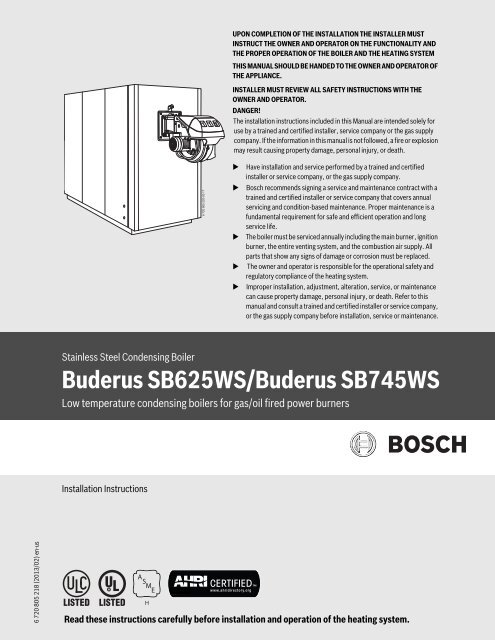
UPON COMPLETION OF THE INSTALLATION THE INSTALLER MUSTINSTRUCT THE OWNER AND OPERATOR ON THE FUNCTIONALITY ANDTHE PROPER OPERATION OF THE BOILER AND THE HEATING SYSTEMTHIS MANUAL SHOULD BE HANDED TO THE OWNER AND OPERATOR OFTHE APPLIANCE.INSTALLER MUST REVIEW ALL SAFETY INSTRUCTIONS WITH THEOWNER AND OPERATOR.DANGER!The installation instructions included in this Manual are intended solely foruse by a trained and certified installer, service company or the gas supplycompany. If the information in this manual is not followed, a fire or explosionmay result causing property damage, personal injury, or death.6 720 805 220-00.1THave installation and service performed by a trained and certifiedinstaller or service company, or the gas supply company.<strong>Bosch</strong> recommends signing a service and maintenance contract with atrained and certified installer or service company that covers annualservicing and condition-based maintenance. Proper maintenance is afundamental requirement for safe and efficient operation and longservice life.The boiler must be serviced annually including the main burner, ignitionburner, the entire venting system, and the combustion air supply. Allparts that show any signs of damage or corrosion must be replaced.The owner and operator is responsible for the operational safety andregulatory compliance of the heating system.Improper installation, adjustment, alteration, service, or maintenancecan cause property damage, personal injury, or death. Refer to thismanual and consult a trained and certified installer or service company,or the gas supply company before installation, service or maintenance.Stainless Steel Condensing BoilerBuderus SB625WS/Buderus SB745WSLow temperature condensing boilers for gas/oil fired power burnersInstallation Instructions6 720 805 218 (2013/02) en-usRead these instructions carefully before installation and operation of the heating system.
2 | ContentsContents1 Key to symbols and safety instructions . . . . . . . . . . . . . . . . . . 31.1 Explanation of symbols . . . . . . . . . . . . . . . . . . . . . . . . . . 31.2 General safety instructions . . . . . . . . . . . . . . . . . . . . . . . 32 Product Description . . . . . . . . . . . . . . . . . . . . . . . . . . . . . . . . . . . 52.1 Intended use . . . . . . . . . . . . . . . . . . . . . . . . . . . . . . . . . . . 62.2 Certification and testing mark . . . . . . . . . . . . . . . . . . . . . 62.3 Regulations and Guidelines . . . . . . . . . . . . . . . . . . . . . . . 62.3.1 National regulation . . . . . . . . . . . . . . . . . . . . . . . . . . . . . . 62.3.2 Compliance with standards and regulations . . . . . . . . . . 62.3.3 Additional regulations for installations in theCommonwealth of Massachusetts . . . . . . . . . . . . . . . . . 62.4 Suitable fuels . . . . . . . . . . . . . . . . . . . . . . . . . . . . . . . . . . 72.5 Scope of delivery . . . . . . . . . . . . . . . . . . . . . . . . . . . . . . . 82.6 Accessories . . . . . . . . . . . . . . . . . . . . . . . . . . . . . . . . . . . . 82.7 Tools, materials and auxiliary equipment . . . . . . . . . . . . 82.8 Data plate . . . . . . . . . . . . . . . . . . . . . . . . . . . . . . . . . . . . . 82.9 Dimensions and specifications . . . . . . . . . . . . . . . . . . . . 92.9.1 Dimensions . . . . . . . . . . . . . . . . . . . . . . . . . . . . . . . . . . . . 92.9.2 Technical Data . . . . . . . . . . . . . . . . . . . . . . . . . . . . . . . . 102.9.3 Water connections . . . . . . . . . . . . . . . . . . . . . . . . . . . . . 113 Water treatment . . . . . . . . . . . . . . . . . . . . . . . . . . . . . . . . . . . . . 133.1 Chemical and physical characteristics . . . . . . . . . . . . . 133.2 Central heating system . . . . . . . . . . . . . . . . . . . . . . . . . 133.2.1 Limescale deposits . . . . . . . . . . . . . . . . . . . . . . . . . . . . . 133.2.2 Deposit corrosion . . . . . . . . . . . . . . . . . . . . . . . . . . . . . . 143.2.3 Stray current corrosion . . . . . . . . . . . . . . . . . . . . . . . . . 143.2.4 Diffused and localized acid corrosion . . . . . . . . . . . . . . 143.3 New central heating systems . . . . . . . . . . . . . . . . . . . . . 143.4 Reconditioning old heating systems . . . . . . . . . . . . . . . 143.5 Elimination air and gas from central heating system . . 143.6 Use of Antifreeze . . . . . . . . . . . . . . . . . . . . . . . . . . . . . . 154 Transport . . . . . . . . . . . . . . . . . . . . . . . . . . . . . . . . . . . . . . . . . . . 165 Installation . . . . . . . . . . . . . . . . . . . . . . . . . . . . . . . . . . . . . . . . . . 175.1 Boiler Clearances . . . . . . . . . . . . . . . . . . . . . . . . . . . . . . 175.2 Assembling the paneling . . . . . . . . . . . . . . . . . . . . . . . . 185.3 Refitting the door hinges . . . . . . . . . . . . . . . . . . . . . . . . 205.3.1 Changing the direction of door opening . . . . . . . . . . . . 205.3.2 Removing the hinge assembly “B” . . . . . . . . . . . . . . . . . 235.4 Burners . . . . . . . . . . . . . . . . . . . . . . . . . . . . . . . . . . . . . . 235.5 Combustion gas exhaust . . . . . . . . . . . . . . . . . . . . . . . . 245.6 Venting Requirements . . . . . . . . . . . . . . . . . . . . . . . . . . 255.7 Code Required Vent Terminations . . . . . . . . . . . . . . . . 255.8 Combustion Air from outside the building . . . . . . . . . . 255.9 Combustion Air from an adjacent room . . . . . . . . . . . . 265.10 Condensate Removal . . . . . . . . . . . . . . . . . . . . . . . . . . . 265.11 Condensate . . . . . . . . . . . . . . . . . . . . . . . . . . . . . . . . . . . 265.11.1 Draining the condensate . . . . . . . . . . . . . . . . . . . . . . . . 265.11.2 Neutralizing the condensate . . . . . . . . . . . . . . . . . . . . . 266 Commissioning . . . . . . . . . . . . . . . . . . . . . . . . . . . . . . . . . . . . . . 286.1 Control unit settings . . . . . . . . . . . . . . . . . . . . . . . . . . . . 286.2 Hydraulic connection to the heating system . . . . . . . . 296.3 Hydraulic flow through boiler . . . . . . . . . . . . . . . . . . . . 296.4 Making the electrical connection . . . . . . . . . . . . . . . . . 306.5 Fitting temperature sensors . . . . . . . . . . . . . . . . . . . . . 316.6 Flushing the heating system . . . . . . . . . . . . . . . . . . . . . 316.7 Filling the heating system . . . . . . . . . . . . . . . . . . . . . . . 326.8 Preparing the heating system for operation . . . . . . . . . 326.9 Commissioning the control unit and burner . . . . . . . . . 326.10 Setting control unit parameters . . . . . . . . . . . . . . . . . . 326.11 Commissioning report . . . . . . . . . . . . . . . . . . . . . . . . . . 337 Shutting down . . . . . . . . . . . . . . . . . . . . . . . . . . . . . . . . . . . . . . . 347.1 Shutting down the heating system . . . . . . . . . . . . . . . . 347.2 Shutting down the heating system in an emergency . . 348 Inspection and maintenance . . . . . . . . . . . . . . . . . . . . . . . . . . 358.1 Why is regular maintenance important? . . . . . . . . . . . . 358.2 Maintenance . . . . . . . . . . . . . . . . . . . . . . . . . . . . . . . . . . 358.2.1 Opening the door . . . . . . . . . . . . . . . . . . . . . . . . . . . . . . 358.2.2 Adjusting the door . . . . . . . . . . . . . . . . . . . . . . . . . . . . . 358.3 Cleaning the boiler . . . . . . . . . . . . . . . . . . . . . . . . . . . . . 368.4 Checking and correcting the water pressure . . . . . . . . 378.4.1 When should you check the water pressure in theheating system? . . . . . . . . . . . . . . . . . . . . . . . . . . . . . . . 378.4.2 Sealed unvented systems . . . . . . . . . . . . . . . . . . . . . . . 378.5 Inspection and maintenance reports . . . . . . . . . . . . . . 389 Spare parts . . . . . . . . . . . . . . . . . . . . . . . . . . . . . . . . . . . . . . . . . 4010 Troubleshooting . . . . . . . . . . . . . . . . . . . . . . . . . . . . . . . . . . . . . 4711 Environmental protection/disposal . . . . . . . . . . . . . . . . . . . . 4812 Glossary . . . . . . . . . . . . . . . . . . . . . . . . . . . . . . . . . . . . . . . . . . . . 496 720 805 218 (2013/02)SB625WS/SB745WS
Key to symbols and safety instructions | 31 Key to symbols and safety instructions1.1 Explanation of symbolsWarningsKeywords at the start of a warning indicate the type and seriousness ofthe ensuing risk if measures to prevent the risk are not taken.The following keywords are defined and can be used in this document:• NOTE indicates that property damage may occur.• CAUTION indicates that personal injury may occur.• WARNING indicates that severe personal injury may occur.• DANGER indicates that severe personal injury or death may occur.Important informationAdditional symbolsSymbol▶Warnings in this document are identified by a warningtriangle printed against a grey background.Important information for the proper use of the boiler isalso provided in this manual. You will find theinformation with a symbol shown on the left andbordered by horizontal lines above and below the text.MeaningSequence of stepsCross-reference to other points in this document or toother documents• Listing/list entry– Listing/list entry (2nd level)Table 11.2 General safety instructionsIf you hear gas leaking▶ Leave the building immediately.▶ Prevent others from entering the building.▶ Notify the police and fire department from outside the building.▶ From outside the building, call the gas supply company and a trainedand certified installer or service company.If you smell gas▶ Turn off the gas shut-off valve.▶ Open windows and doors▶ Do not touch any electrical switch, telephone, and do not use outlets.▶ Extinguish all open flames.▶Do not smoke!▶ Do not use lighters!▶ Warn all occupants of the building that they need to leave the building.▶ Do not ring doorbells!▶ Notify the police and fire department from outside the building.▶ From outside the building, call the gas supply company and a trainedand certified installer or service company.If you smell flue gas▶ Switch off the heating system by shutting off the emergency shut-offswitch.▶ Open windows and doors.▶ Call a trained and certified installer or service company.DANGER: Risk of fatal injury from failing to consider your ownsafety!▶ Never risk your own life. Your own safety must always take the highestpriorityNOTICE: Risk of appliance damage from improper operation of theboiler!▶ Only use the boiler for its intended purpose.▶ Only operate the boiler if it has been installed and maintained per theinstructions provided in the Installation Manual.▶ Do not attempt to operate an appliance if any part of it is not inworking order or is damaged.▶ Use only original spare parts! The use of parts not supplied by themanufacturer may cause damage to the boiler, other property andpersonal injury. Also, boiler damage caused by the use ofunauthorized parts is not covered by the warranty.DANGER: Risk of fire when soldering and brazing!▶ Take appropriate protective measures when soldering and brazingaround combustible and flammable material.NOTICE:▶ The installation must comply with all applicable national, state, andlocal codes, rules, and regulations.▶ The operator is responsible for the operational safety and regulatorycompliance of the heating system.▶ In the Commonwealth of Massachusetts, the appliance must beinstalled by a licensed plumber or gas fitter.DANGER: Risk of personal injury or death from flue gas poisoning!▶ Do not install a thermostatic flue gas damper downstream of the drafthood.▶ Do not tamper with, remove, or attempt to repair the blocked ventswitch.▶ When replacing the blocked vent switch, install the new part in theoriginal location.▶ A blocked vent switch tripping more than once indicates a problemwith the venting system or chimney which must be repairedimmediately.▶ Ensure none of the vent pipes and chimneys are damaged or blocked.▶ Connect only one appliance to each venting system or chimney.▶ The venting system must not feed into or route through another airextraction duct.▶ The venting system must be inspected annually. All parts that showany signs of damage or corrosion must be replaced.▶ Never close off or reduce the size of the combustion air openings.▶ The boiler must not be operated until any obstructions have beenremoved.SB625WS/SB745WS6 720 805 218 (2013/02)
4 | Key to symbols and safety instructionsDANGER: Risk of personal injury or death from explosion!▶ Work on gas components may only be carried out by a trained andcertified installer or service company.▶ Appliance installation, the connection of gas and vent piping, initialcommissioning, electrical connections, and service and maintenancemust only be carried out by a trained and certified installer or servicecompany.DANGER: Risk of personal injury or death from fire!▶ Do not use flammable or combustible material in the boiler room.▶ It is recommended not to store any items within 16 inches (415mm)of the applianceCAUTION: Appliance damage from contaminated combustion air!▶ Keep the combustion air free of corrosive substances, e.g.halogenated hydrocarbons from painting operations or beautysalons.▶ Keep combustion air free from dust and lint, e.g. from laundry oragricultural operations.▶ If clean room air is not available, fresh outdoor combustion air must beprovidedDANGER: Risk of personal injury or death from electric shock.▶ Before removing the front panel, disconnect the heating system fromthe electrical power supply by shutting off the emergency shutoffswitch or the heating system circuit breaker.▶ It is not enough to switch off the control panel. Power to the panelmust be disconnected! Ensure that the power is not restoredunintentionally by following proper lock out/tag out procedures.▶ Only qualified electricians are permitted to carry out electrical work.DANGER: Safety devices!▶ Never shut off safety valves!▶ Hot water may escape from the safety valve at any time when theappliance is running.DANGER: Risk of personal injury or death after a flood!▶ Do not attempt to operate an appliance if any part of it has been underwater.▶ An appliance that was subject to flooding must be replaced.NOTICE:▶ Upon completion of the installation, these instructions should behanded to the owner and operator of the appliance.▶ The installer must instruct the owner and operator on the functionalityof the components and the proper operation of the boiler and theheating system.▶ The boiler must be serviced annually including the main burner,ignition burner, the entire venting system, and the combustion airsupply. All parts that show any signs of damage or corrosion must bereplaced.6 720 805 218 (2013/02)SB625WS/SB745WS
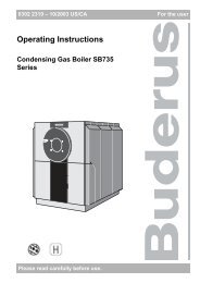
Product Description | 52 Product DescriptionThe high efficiency SB Series boilers are designed to condense fluegases through a unique three-pass construction for installation in amechanical room. While they are designed primarily for central heatingpurposes, in conjunction with a suitable storage tank they can also beused to produce domestic hot water.All parts that come into contact with the combustion gases are madefrom titanium stabilized stainless steel to ensure maximum resistance tothe corrosive action of acid condensation.The boiler has been designed with the combustion chamber at the topand the smooth pipe tube bundle at the bottom to optimize heatexchange and to maximize the condensing effect.The boiler has a high total water content which is differentiallydistributed between its top and bottom sections. This hydraulic featureallows outgoing water to reach the set temperature quickly whilemaintaining the condensing effect and the water heating time around thetube bundle for as long as possible.The boilers feature lightly pressurized combustion chambers for asmoother burner action, and high temperature resistant, stainless steelturbulators inside the tube bundle for maximum burner efficiency.The boiler body is thoroughly insulated with a layer of high density glasswool.The paint finished external paneling is also internally insulated with alayer of high density glass wool.The boiler’s front door and the flue gas chamber can be openedcompletely to facilitate the inspection, maintenance and cleaning ofinternal parts and to speed up servicing in general.The front door can open in either direction and can be opened withoutremoving the burner. The door is factory fitted with hinges on the left,but these can be reversed if necessary to suit individual installations.1 2 3 4 561817716151413Fig. 1 Main components[1] Paneling[2] Heating flow outlet[3] Safety device fitting 1)[4] Heating return (high temperature)[5] Heating return (low temperature) 2)[6] Instrument for bulb/probe socket[7] Combustion chamber1) On the 1550WS model the low temperature heating return is located at the rearof the boiler.2) On the 745WS models (800-1550) the safety device fitting is flanged.[8] Flue connection[9] Flue gas box[10] Inspection port[11] Condensate drain[12] Boiler drain[13] Turbulators[14] Flue pipes[15] Second flue pass[16] Burner[17] Flame inspection window with pressure measurement point[18] Door891011126 720 805 218-01.1TSB625WS/SB745WS6 720 805 218 (2013/02)
6 | Product Description2.1 Intended useThis boiler must only be used for the purpose specified by themanufacturer and for which it is designed.The SB625WS/SB745WS can be operated with gas, oil, andcombination burners. For a list of the approved burners, please contact<strong>Bosch</strong> <strong>Thermotechnology</strong> Corp.The boiler can be operated with an aquastat, the Logamatic 4000, andother control systems.The manufacturer declines all responsibility, contractual or other, fordamage to property or injury to persons or animals caused by improperinstallation, adjustment, maintenance or use.2.2 Certification and testing markThis appliance has been tested and certified and meets all applicablestandards for the US and Canadian markets:• CSA-AM 3.1 Industrial and commercial gas-fired package boilers• CSA B140.0 General requirements for oil burning equipment• CSA B140.2.1-10 Atomizing-type oil burners• CSA B140.7-05 Oil-burning equipment - steam and hot water boilers• UL 296 Standard for oil burners• UL 726 Standard for oil-fired boiler assemblies• UL 795 Standard for commercial industrial gas heating equipment2.3 Regulations and Guidelines2.3.1 National regulationThe heating system must comply with the requirements of the relevantregulatory authorities or otherwise of the National Fuel Gas Code, ANSIZ 223.1 In Canada, the requirements of CAN/CGA-B.149.1 and 2, orCAN/CGA-B.139 must be observed.If specified by the relevant regulatory authorities, the heating systemmust comply with the regulations of the Standard for Controls andSafety Devices for Automatically Fired Boilers, ANSI/ASME CSD-1.Carbon monoxide detectors must be installed as specified by the localregulations. The boiler must be serviced annually.2.3.2 Compliance with standards and regulationsInstallation of the boiler must comply with all applicable codes andregulations imposed by the national, Federal or local authorities andbodies. If no specific requirements are defined, in the USA, the latestedition of the National Fuel Gas Code ANSI Z223.1/NFPA 54 must becomplied with.In Canada, installation must comply in all respects with the latest editionof the Natural Gas and Propane Installation Code, CAN/CGA-B. 149, theInstallation Code for Oil Burning Equipment, CAN/CGA-B. 139 and theapplicable local regulations and requirements for the appliancecategory. The relevant authorities and regulatory bodies must beinformed before installation starts.Where required by local regulations, the system must comply with theAmerican Society of Mechanical Engineers Safety Code for Controls andSafety Devices for Automatically Fired Boilers (ASME CSD-1).The local regulations regarding minimum pressure detectors and lowwatersafety cutouts must be observed. Installation and operation mustcomply with the device manufacturer‘s technical documentation.We recommend fitting an 80 mesh dirt filter externally to the boilerreturn to prevent contamination of the boiler by the water source.Leak testA leak test must be carried out. The testing pressure is based on thenormal operating pressure of the heating system and should be 1.3times that pressure, and in any case no less than 14 psi (1 bar).Safety limitsWARNING: Risk of fatal Injury from explosion offlammable gases!▶ Installation, connection of the fuel supply and fluepipe, commissioning, connection of the electricalpower supply, servicing and repair may only becarried out by an authorized heating engineer.▶ Any work on gas-carrying components may only becarried out by an authorized gas installer.The details on the boiler rating plate are definitive andmust be observed.Safety limitsMaximum allowable temperature: 230 °F(110 °C)Maximum operating temperature 210 °F(98.8 °C)Permissible operating pressure:Maximum cycle time for:Safety temperature limiter:Temperature control:Table 2 Safety limits80 psi(5.5 bar)40 s40 s2.3.3 Additional regulations for installations in theCommonwealth of Massachusetts(a) For all side wall horizontally vented gas fueled equipment installed inevery dwelling, building or structure used in whole or in part forresidential purposes, including those owned or operated by theCommonwealth and where the side wall exhaust vent termination is lessthan seven (7) feet above finished grade in the area of the venting,including but not limited to decks and porches, the followingrequirements shall be satisfied:• INSTALLATION OF CARBON MONOXIDE DETECTORS. At the time ofinstallation of the side wall horizontal vented gas fueled equipment,the installing plumber or gasfitter shall observe that a hard wiredcarbon monoxide detector with an alarm and battery back-up isinstalled on the floor level where the gas equipment is to be installed.In addition, the installing plumber or gasfitter shall observe that abattery operated or hard wired carbon monoxide detector with analarm is installed on each additional level of the dwelling, building orstructure served by the side wall horizontal vented gas fueledequipment. It shall be the responsibility of the property owner to6 720 805 218 (2013/02)SB625WS/SB745WS
Product Description | 7secure the services of qualified licensed professionals for theinstallation of hard wired carbon monoxide detectors.– In the event that the side wall horizontally vented gas fueledequipment is installed in a crawl space or an attic, the hard wiredcarbon monoxide detector with alarm and battery back-up may beinstalled on the next adjacent floor level.– In the event that the requirements of this subdivision cannot be metat the time of completion of installation, the owner shall have aperiod of thirty (30) days to comply with the above requirements;provided, however, that during said thirty (30) day period, abattery operated carbon monoxide detector with an alarm shall beinstalled.• APPROVED CARBON MONOXIDE DETECTORS. Each carbonmonoxide detector as required in accordance with the aboveprovisions shall comply with NPA 720 and be ANSI/UL 2034 listedand IAS certified.• SIGNAGE. A metal or plastic identification plate shall be permanentlymounted to the exterior of the building at a minimum height of eight(8) feet above grade directly in line with the exhaust vent terminal forthe horizontally vented gas fueled heating appliance or equipment.The sign shall read, in print size no less than one-half (½) inch in size,“GAS VENT DIRECTLY BELOW. KEEP CLEAR OF ALLOBSTRUCTIONS”.• INSPECTION. The state or local gas inspector of the side wallhorizontally vented gas fueled equipment shall not approve theinstallation unless, upon inspections, the inspector observes carbonmonoxide detectors and signage installed in accordance with theprovisions of 248 CRM 5.08(2)(a) 1 through 4.(b) EXEMPTIONS: The following equipment is exempt from 248 CRM5.08(2)(a) 1 through 4:• The equipment listed in Section 10 entitled “Equipment Not RequiredTo Be Vented” in the most current edition of NFPA 54 as adopted bythe board; and• Product Approved side wall horizontally vented gas fueled equipmentinstalled in a room or structure separate from the dwelling, building orstructure used in whole or in part for residential purposes.(c) MANUFACTURERS REQUIREMENTS - GAS EQUIPMENT VENTINGSYSTEM REQUIRED. When the manufacturer of Product Approved sidewall horizontally mounted gas equipment provides a venting systemdesign or venting system components with the equipment, theinstructions provided by the manufacturer for the installation of theequipment and venting shall include:• Detailed instructions for the installation of the venting system or theventing system components; and• A complete parts list for the venting system design or venting system.(d) MANUFACTURERS REQUIREMENTS - GAS EQUIPMENT VENTINGSYSTEM NOT PROVIDED. When the manufacturer of Product Approvedside wall horizontally vented gas fueled equipment does not provide theparts for the venting of flue gases, but identifies “special ventingsystems”, the following requirements shall be satisfied by themanufacturer:• The referenced “special venting systems” shall be included with theappliance or equipment installation instructions; and• The “special venting systems” shall be Product Approved by theBoard, and the instructions for that system shall include a parts listand detailed installation instructions.(e) A copy of all instructions for all Product Approved side wallhorizontally vented gas fueled equipment, all venting instructions, allparts lists for venting instructions, and/or venting design instructionsshall remain with the appliance or equipment at the completion of theinstallation.2.4 Suitable fuelsPermissible fuels• Natural gas from the public gas supply in accordance with nationalregulations with a total sulphur content < 15ppm.• LP in accordance with national regulations with a content ofelementary sulphur < 1.5 ppm and volatile sulphur < 50 ppm.• Ultra Low Sulphur Diesel in accordance with national regulations witha content of elementary sulphur < 15 ppm (for use as back-up fuel incondensing operation).• Heating oil type 2 when boiler return temperature is not lower than140 degrees Fahrenheit; non-condensing operation (for use as backupfuel only). See the warranty statement for additional details.NOTICE:▶ Do not use gasoline, crankcase drainings, or any oilcontaining gasoline.The boiler must only be operated with the specifiedfuels.Only burners that are suitable for the specified fuels maybe used.Observe the manufacturer's burner selection list and theburner manufacturer's instructions.SB625WS/SB745WS6 720 805 218 (2013/02)
8 | Product Description2.5 Scope of deliveryThe boilers SB625WS / SB745WS comes in two separate crates andone additional box.Boiler body crate:The boiler body crate bears the documentation envelope [1] andcontains:• Instruction manual• Certificate of Warranty• Bar code labels• Ceramic insulation [2]1The instruction manual is an integral part of the boiler.Once located, read it thoroughly and keep it safe.Accessory box:The boiler accessory box contains• Manifold• Pressure relief valve• Pressure/temperature gaugeChecking the delivery for completeness▶ After delivery, check all packaging is in perfect condition.▶ Check the delivery for completeness.▶ Dispose of packaging in an environmentally responsible manner.2.6 AccessoriesControl panelsThe control panels listed below may be supplied by the manufacturer foruse with the SB625WS / SB745WS boilers.ModelDescriptionThe Logamatic 4321 control unitis designed for low temperatureand condensing operation insingle or multiple boiler systems.Additional possible functionsinclude DHW, mixed heating zonesand solar thermal integration.Table 3 Control panelsFig. 22Boiler body crate6 720 805 218-11.2TPaneling crate:The paneling crate, complete with assembly accessories, protected bycardboard packaging and a wooden crate.2.7 Tools, materials and auxiliary equipmentFor the installation and maintenance of the boiler, standard tools arerequired, as used for heating, gas, water and electrical installations.2.8 Data plateIf you contact the manufacturer with any questions aboutthis product, always provide the details on the data plateand serial number plate. These details enable us to assistyou specifically and quickly.Serial number plateThe serial number plate is located on the rear of the boiler block andspecifies the serial number and model.Data plateThis lists the appliance’s technical specifications and performance. Thedata plate will be factory installed on the boiler side panel.If these plates or any other means of clearly identifyingthe product are defaced, removed or lost, properinstallation and servicing may be difficult.Fig. 3Paneling crate6 720 805 218-12.1T6 720 805 218 (2013/02)SB625WS/SB745WS
Product Description | 92.9 Dimensions and specificationsValues obtained with RS.../M-burners.2.9.1 DimensionsFDHH1CL1EALB6 720 805 218-13.1TFig. 4DimensionsDescription Unit SB625WS SB745WS160 220 290 370 480 640 800 1050 1300 1550A: Base width inch(mm)B: Overall width inch(mm)C: Length base tofrontD: Height of burnerplateE: Length base torearF: Flue connectiondepthH – Height of waterfittingsH1 – Boiler heightinch(mm)inch(mm)inch(mm)inch(mm)inch(mm)inch(mm)L – Lengthinch(mm)L1 – Base length inch(mm)Weight of boiler lbs(kg)Weight of paneling lbs(kg)Table 4 Technical Data27 3/16(690)29 1/8(740)4 3/4(120)36 7/16(925)1 9/16(40)2 3/4(70)52 3/4(1340)52 3/16(1325)57 5/16(1455)60(1295)1122(510)110(50)27 3/16(690)29 1/8(740)4 3/4(120)36 7/16(925)1 9/16(40)2 3/4(70)52 3/4(1340)52 3/16(1325)57 5/16(1455)60(1295)1168(530)110(50)29 1/2(750)33 1/2(850)4 3/4(120)40 9/16(1030)1 9/16(40)2 3/4(70)57 1/16(1450)56 9/16(1435)64 3/16(1630)57 7/8(1470)1492(677)132(60)29 1/2(750)33 1/2(850)4 3/4(120)40 9/16(1030)1 9/16(40)2 3/4(70)57 1/16(1450)56 9/16(1435)72 1/16(1830)65 3/4(1670)1660(753)154(70)31 1/8(790)35 7/16(900)4 3/4(120)48 5/8(1235)1 9/16(40)2 3/4(70)66 3/4(1695)66 1/8(1680)80 1/8(2035)73 13/16(1875)2414(1095)198(90)31 1/8(790)35 7/16(900)4 3/4(120)48 5/8(1235)1 9/16(40)2 3/4(70)66 3/4(1695)66 1/8(1680)88(2235)81 11/16(2075)2755(1250)264(120)37 7/16(950)41 3/4(1060)4 3/4(120)54 3/4(1390)1 9/16(40)2 3/4(70)75(1905)74 7/16(1890)100 3/4(2560)94 1/2(2400)4122(1870)308(140)37 7/16(950)41 3/4(1060)4 3/4(120)54 3/4(1390)1 9/16(40)2 3/4(70)75(1905)74 7/16(1890)110 5/8(2810)104 5/16(2650)4596(2085)352(160)42 1/8(1070)46 7/16(1180)4 3/4(120)58 7/8(1495)1 9/16(40)2 3/4(70)80 5/16(2040)79 3/4(2025)118 1/2(3010)112 3/16(2850)5544(2515)473(215)44 1/2(1130)48 1/4(1225)4 3/4(120)62 5/8(1590)1 9/16(40)2 3/4(70)85 13/16(2180)85 1/4(2165)121 1/4(3080)112 3/16(2850)6724(3050)506(230)SB625WS/SB745WS6 720 805 218 (2013/02)
10 | Product Description2.9.2 Technical DataDescription SB625WS SB745WS160 220 290 370 480 640 800 1050 1300 1550Fuel Gas Gas Gas Gas Gas Gas Gas Gas Gas GasRated input (Nat. Gas)Rated input (#2 Oil)Gross outputSensible losses fromstackJacket losses with burnermountedFlue gas temperature(T)Flue gas mass flow rate 1Fireside pressure drop 2Firebox volumeTotal volume of flue gassideHeat exchanger surfaceareaSpecific heat loadMaximum condensateproductionMaximum workingpressureMaximum admissibletemperatureMaximum workingtemperaturePressure drop T50 °F (10 °C)Pressure drop T68 °F (20 °C)Water capacity<strong>MB</strong>H(kW)GPH(LPH)<strong>MB</strong>H(kW)563(164.9)4.0(15.1)544(159.7)788(230.9)5.6(21.2)762(223.6)1014(297.1)7.2(27.3)990(290.2)1314(385.0)9.3(35.2)1280(375.2)1689(494.9)12.0(45.4)1642(481.5)2200(644.7)15.7(59.4)2190(642.0)3003(880.0)21.4(81.0)2738(802.4)3754(1100.0)26.8(101.4)3650(1070.0)4692(1375.0)33.5(126.8)4563(1337.4)% 1.7 1.7 1.5 1.5 1.9 1.9 1.9 1.9 1.9 1.9% 0.3 0.3 0.5 0.6 0.6 0.6 0.6 0.6 0.6 0.6°F(°C)lbs/sec(kg/sec)InchW.C(mbar)Ft3(dm3)Ft3(dm3)Ft2(m2)<strong>MB</strong>H/ft2(kw/m2)Gal/h(l/h)PSI(bar)°F(°C)°F(°C)Ft. Hd.(mbar)Ft. Hd.(mbar)Gal(l)< 113 - 167(< 45 - 75)0.15(0.07)0.802(2.0)6.07(172)8.93(253)65.65(6.1)8.28(26.18)4.86(18.4)80(5.5)230(110)210(98.8)5.0(150.1)1.2(36.3)85.3(323)0.19(0.09)1.083(2.7)6.07(172)9.78(277)94.72(8.8)8.04(25.40)7.23(27.4)80(5.5)230(110)210(98.8)3.3(100.4)0.9(28.4)95.1(360)< 113 - 167(< 45 - 75)0.26(0.12)1.284(3.2)8.51(241)14.58(413)139.93(13.0)7.07(22.32)8.42(31.9)80(5.5)230(110)210(98.8)4.1(121.5)1.0(30.6)130.7(495)0.33(0.15)1.846(4.6)9.85(279)17.02(482)175.45(16.3)7.29(23.01)10.80(40.9)80(5.5)230(110)210(98.8)4.3(128.7)0.9(28.7)146.6(555)Table 5 Technical Data1. Depends on return temperature 86-140 °F (30-60 °C)2. At maximum output with water temps supply/return of 176/140 °F (80/60 °C) and CO2 = 9.7 %< 113 - 167(< 45 - 75)0.44(0.20)2.007(5.0)15.61(442)26.03(737)234.65(21.8)6.99(22.08)13.78(52.2)80(5.5)230(110)210(98.8)1.0(30.2)0.3(8.5)196.2(743)0.57(0.26)2.208(5.5)17.51(496)30.37(860)310.00(28.8)7.06(22.29)19.49(73.8)80(5.5)230(110)210(98.8)1.1(33.8)0.3(9.0)203.4(770)< 113 - 167(< 45 - 75)0.72(0.33)2.288(5.7)26.59(753)45.55(1290)426.25(39.6)6.42(20.26)23.24(88.0)80(5.5)230(110)210(98.8)1.5(46.4)0.4(13.4)348.7(1320)0.94(0.43)2.529(6.3)30.15(854)51.34(1454)500.52(46.5)7.29(23.01)29.42(111.4)80(5.5)230(110)210(98.8)1.8(54.0)0.5(16.3)368.5(1395)< 113 - 167(< 45 - 75)1.19(0.54)2.729(6.8)36.62(1037)62.25(1763)604.93(56.2)7.54(23.79)35.05(132.7)80(5.5)230(110)210(98.8)1.2(36.0)0.3(10.2)482.1(1825)5443(1595.0)38.8(146.9)5293(1551.4)1.38(0.63)2.970(7.4)44.10(1249)74.05(2097)670.37(62.2)7.89(24.94)42.13(159.5)80(5.5)230(110)210(98.8)1.4(43.2)0.4(11.3)501.9(1900)6 720 805 218 (2013/02)SB625WS/SB745WS
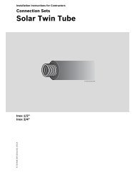
HHProduct Description | 112.9.3 Water connectionsThe boilers are designed and made for use in central heatinginstallations, but can also be used for domestic hot water production ifconnected to suitable sub-systems. Water fittings are as specified in thefollowing table.ABFNE D CMM14327882 3/4”(70 mm)65IOLGFig. 5Water connections - SB625WS/160-640 and SB745/800-13006 720 805 218-18.1TABNE D CMM143282765I FPOLG6 720 805 218-19.1TFig. 6Water connections - SB745WS/1550The choice of system components and the method oftheir installation are left up to the installer. Installersmust use their expertise to ensure proper installationand functioning in compliance with all applicable codes.SB625WS/SB745WS6 720 805 218 (2013/02)
12 | Product DescriptionDescription SB625WS SB745WS160 220 290 370 480 640 800 1050 1300 15501 – Heating supply inch(DN)2 – Heating return 1(Low Temperature)3 – Heating return 2(High Temperature)4 – Safety devicefittinginch(DN)inch(DN)2 1/2(65)2 1/2(65)2(50)2 1/2(65)2 1/2(65)2(50)2 1/2(65)2 1/2(65)2(50)3(80)3(80)2 1/2(65)4(100)4(100)3(80)4(100)4(100)3(80)5(125)5(125)3(80)5(125)5(125)3(80)6(150)6(150)4(100)Ø- inch 1 1/4 1 1/4 1 1/4 1 1/4 1 1/2 1 1/2 3 3 3 36(150)6(150)4(100)5 – Boiler drain fitting Ø - inch 1 1 1 1 1 1 1 1/4 1 1/4 1 1/4 1 1/46 – Condensate drain Ø- inch 1 1 1 1 1 1/4 1 1/4 1 1/4 1 1/4 1 1/4 1 1/4fitting7 – Flue gas exhaust Ømm 200 200 250 250 300 300 350 350 400 450fitting8– Instrument bulb/probe socketsn° x Ø ‘’ 3 x 1/2 3 x 1/2 3 x 1/2 3 x 1/2 3 x 1/2 3 x 1/2 3 x 1/2 3 x 1/2 3 x 1/2 3 x 1/2A– Distance fromburner head to heatingsupplyB– Distance fromheating flow outlet toreturn 1C – Distance betweenheating returns 1 & 2D – Distance betweenheating return 2 andsafety device fittingE – Distance betweenheating flow outlet andsafety device fittingF – Distance betweenheating return 1 andflue gas outletG – Height ofcondensate drainH – Height of boilerflangesI – Height of flue gasoutletL – Height of boilerdrain fittingM – Boiler centerlineN– Distance fromburner head to doorO – Distance fromBoiler drain fittingP – Height of heatingreturn 1(Low Temperature)Table 6 Technical Datainch(mm)inch(mm)inch(mm)inch(mm)inch(mm)inch(mm)inch(mm)inch(mm)inch(mm)inch(mm)inch(mm)inch(mm)inch(mm)inch(mm)11 7/8(302)34 7/8(885)7 7/8(200)11 1/4(285)15 3/4(400)10 5/8(270)6 5/16(160)52 3/4(1340)20 1/4(515)2 3/8(60)13 9/16(345)4 5/16(110)5 3/16(132)11 7/8(302)34 7/8(885)7 7/8(200)11 1/4(285)15 3/4(400)10 5/8(270)6 5/16(160)52 3/4(1340)20 1/4(515)2 3/8(60)13 9/16(345)4 5/16(110)5 3/16(132)11 13/16(300)41 3/8(1050)11 13/16(300)11 13/16(300)17 3/4(450)10 5/8(270)6 1/2(165)57 1/16(1450)21 1/2(545)2 7/16(61)14 9/16(375)4 3/4(120)5 3/8(137)12 5/8(321)48 5/16(1235)9 7/8(250)17 3/4(450)21 1/16(535)10 5/8(270)6 1/2(165)57 1/16(1450)21 1/2(545)2 7/16(61)14 9/16(375)4 3/4(120)5 3/8(137)12 1/4(311)55 5/16(1405)10 1/8(255)23 5/8(600)21 11/16(550)10 5/8(270)8 1/2(215)66 3/4(1695)25 3/8(645)3 1/4(82)15 9/16(395)4 15/16(125)4 15/16(125)12 1/4(311)63 3/16(1605)11 13/16(300)27 9/16(700)23 13/16(605)10 5/8(270)8 1/2(215)66 3/4(1695)25 3/8(645)3 1/4(82)15 9/16(395)4 15/16(125)4 15/16(125)16 1/8(410)70 7/8(1800)13 13/16(350)29 1/2(750)27 9/16(700)12 13/16(325)7 11/16(195)75(1905)26 3/4(680)3 3/8(86)19 5/16(490)4 15/16(125)6 7/8(175)16 1/8(410)80 11/16(2050)13 13/16(350)33 1/2(850)33 1/2(850)12 13/16(325)7 11/16(195)75(1905)26 3/4(680)3 3/8(86)19 5/16(490)4 15/16(125)6 7/8(175)17 5/16(440)86 5/8(2200)13 13/16(350)33 1/2(850)39 3/8(1000)13 5/8(345)8 7/8(225)80 5/16(2040)28 3/8(720)3 1/2(90)21 1/16(535)5 1/2(140)7 1/8(181)17 3/8(442)101 3/4(2582)28 13/16(732)33 1/2(850)39 3/8(1000)22 1/4(565)9 1/4(235)85 13/16(2180)31 11/16(805)3 3/8(86)22 1/4(565)6(150)7(178)– – – – – – – – – 53 7/8(1370)6 720 805 218 (2013/02)SB625WS/SB745WS
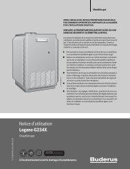
Water treatment | 133 Water treatmentThe quality of the fill and top-up water is an essential factor for increasedefficiency, functional reliability, long service life and for maintaining theconstant operational condition of a heating system. If the system is filledwith water that has a high calcium hardness, this will be deposited on theheat exchanger surfaces and will obstruct the transfer of heat to theheating water.As a result, the wall temperatures of the stainless steel heat exchangersurfaces will increase and the thermal stress (loads on the boiler body)will increase. Water treatment is an essential factor in ensuring troublefree operation, availability, a long service life and the efficiency of theheating system.NOTICE:If it proves impossible to treat the heating system watersupply properly because the water charging system isautomatic and uncontrolled, if there are no barriersinstalled to prevent water oxygenation, and if theheating system includes an open expansion vessel, thenthe boiler itself must be separated from the heatingsystem by means of a heat exchanger.Installation must conform to any and all national, federal,state and local standards and codes.3.1 Chemical and physical characteristicsThe chemical and physical characteristics of heating system water mustbe similar to those of drinking water.A chemical water treatment device is recommended in order to protectsystem components as well as an inlet filter to prevent solid particlesfrom entering the system in suspension and causing corrosion or sludge.Typical layouts of water treatment systemsChemical and physical requirements of heating system waterParameters Unit of measure Heating waterpH 7.5- 9,5Hardness ppm
14 | Water treatmentspecific areas, where temperature is the highest. A coating of limescaleof only 1 mm can cause severe overheating in metal parts andconsequent damage through thermal stress. It is continuous topping up(automatic fill from incoming water) that causes thick deposits to form,leading to boiler breakdown.3.2.2 Deposit corrosionDeposit corrosion is an electro-chemical phenomenon caused by thepresence of foreign bodies (sand, rust, etc.) in the water mass. Thesesolid substances generally form deposits (sludge) in the bottom of theboiler.The lower parts of the boiler can therefore be affected by a chemicalreaction of micro-corrosion caused by the electrochemical potentialdifference created between the metal (steel) and the impurities aroundit.3.2.3 Stray current corrosionStray current corrosion is not common, but can be caused by thedifferent electrical potentials of the boiler water and the metal body ofthe boiler or piping creating a cathode/anode effect.All metal parts of the boiler should therefore be connected to an efficientground (earth) point, even though this form of corrosion is actuallycaused by the passage of DC current, no longer used for domesticpower. Stray current corrosion is easily identified by the regular tinyconical holes it leaves.3.2.4 Diffused and localized acid corrosionOther forms of corrosion exist that are harder to see but nonethelessdangerous because they affect the entire heating system and not just theboiler.These forms of corrosion are generally due to the water becoming acidic(pH < 7), and are caused by:• Incorrect water softening and the presence of carbon dioxide (whichlowers the water’s pH). Carbon dioxide is released more easily insoftened water and also forms during the limescale formationprocess. Acid corrosion is diffused and attacks the entire systemmore or less uniformly• Incorrect acid washing (e.g. washing done without a passivatingagent). Acid introduced into the system can cause localizedperforation if it is not properly removed from all parts of the system.The formation of corrosion can easily be detected by analyzing thechemical composition of the water. Even a minimal iron content is aclear sign that corrosion is occurring.The technical details provided in this section referspecifically to domestic and industrial hot water heatingsystems with working temperatures up to 210 °F(98,8 °C).3.3 New central heating systemsMistakes to avoid and precautions.To eliminate contact between system water and the air, the following isrequired:• ensure that the expansion vessel is a closed vessel, and of the correctsize and pre-charge pressure (the pressure should be checkedperiodically)• ensure that the system is always kept at a pressure higher thanatmospheric pressure at all points (including the pump suction side)and at all operating conditions (precisely because the seals, gasketsand joints in a water circuit are designed to resist pressure fromwithin, but not to resist a vacuum within)• ensure that no part of the system is made from materials that arepermeable to gases (e.g. plastic pipes with no oxygen barrier used infloor heating systems).NOTICE:The original system filling water and any topping upwater must always be filtered (using synthetic or metalmesh filters with a filtration rating of no less than 50microns) to prevent sludge from forming and triggeringdeposit induced corrosion.NOTICE:Loss of water from the system, and the consequentialneed to add water, can be caused not only by leaks fromthe circuit, but also from the incorrect sizing of theexpansion vessel or precharge pressure. (If normalthermal expansion causes pressure in the system toincrease beyond the setting of the safety valve, thatsafety valve will open continuously.)The expansion vessel size should be corrected toprevent unnecessary safety valve blow-off.The heating system should not need any further topping up once it isfilled and bled of all air.Any top-ups need to be monitored (by a meter), treated and recorded inthe heating system’s technical log. The presence of a water softener inconjunction with an automatic filling system is not sufficient to ensureproper performance.If more than one boiler is installed in a large system, all boilers must beswitched on at the same time to ensure that any possible limescaleformation is uniformly distributed.3.4 Reconditioning old heating systemsFrequent mistakes and necessary precautions.If a boiler must be replaced, do not refill the entire central heating circuitif the quality of water in it conforms to requirements.If the quality of water fails to conform to requirements, eitherrecondition the old water or separate the water circuits (water in theboiler circuit must conform to requirements).ConclusionsNever forget that proper water conditioning and proper heating systemdesign not only guarantee safety and security but also ensuressignificant savings in maintenance costs and overall thermal efficiency.3.5 Elimination air and gas from central heating systemWhen designing new heating systems, it is necessary to eliminate the airand other gases that form in the system.Recently added fill or top-up water loses much of its volume in the firstfew days because it releases gases. With new systems you shouldtherefore initially check the heating water pressure on a daily basis, andthen at gradually longer intervals. Air and gas in the water system notonly causes the corrosion problems listed above, but also reducesthermal efficiency, causing pump failure and noise and vibrationthroughout the heating system. Air bubbles and gas inevitably form inheating circuits during normal functioning, especially if the precautionslisted above are not fully respected.6 720 805 218 (2013/02)SB625WS/SB745WS
Water treatment | 15In particular:• as temperature increases, oxygen becomes less watersoluble andbubbles begin to form.• CO2 (carbon dioxide) is generated as the carbonates of calcium andmagnesium precipitate out.• the chemical oxidation of the metals in the system also generateshydrogen.These gases must be eliminated as they are formed. The system needsto be designed and installed so that all gases can be vented quickly,easily, and effectively.3.6 Use of AntifreezeDo not use automotive silicate-based antifreeze in theheating system.In areas where freezing may occur, an antifreeze may be added to thesystem water as protection. Please adhere to the specificationsprovided by the antifreeze manufacturer.▶ Use the anti-freeze manufacturer’s data to determine the anti-freezeratio for the desired freeze protection temperature.▶ Do not exceed 50% antifreeze mix ratio and do not use antifreezeother than specifically made for hot water heating systems.SB625WS/SB745WS6 720 805 218 (2013/02)
16 | Transport4 TransportWARNING: Risk of injury from carrying heavy loads andinadequately securing loads for transport.▶ Use suitable means of transportation, e.g. severalpallet trucks, a forklift truck, crane or heavy dutyrollers.▶ Secure the load against falling.▶ Only use lifting equipment of adequate capacity.▶ Remove the transport straps and the wooden pallet beforepositioning the boiler.▶ For lifting using a rigging crane, use only the lifting provisionssupplied.▶ When lifting the boiler using chains, make sure that at least two chainsare load-bearing. Lift up very carefully.▶ Maintain less than a 45 degree angle with the vertical when lifting theboiler with chains or cables.▶ The rigging crane must be operated by trained personnel.Never pull retaining straps (fixing straps, chains) overthe boiler insulation.Fig. 8Transport6 720 805 218-14.1T6 720 805 218 (2013/02)SB625WS/SB745WS
Installation | 175 Installation5.1 Boiler ClearancesA1B1B2DB1B2CA26 720 805 218-52.1TFig. 9Installation siteNOTICE: Risk of system damage through frost.▶ Do not install the boiler outdoors; it is not designed towork outdoors and is not fitted with the necessaryautomatic anti-frost systems to do so.▶ Ensure that the boiler installation room remains freefrom the risk of frost.Installation room requirements:In the boiler installation room, an ambient temperature of between 32 °Fand 95 °F (0 °C and 35 °C) must be ensured.The boilers must be installed in a dedicated boiler room, with adequatelysized vents, in compliance with applicable codes and standards.If at all possible, the boiler should be installed on a raised base to preventthe burner fan from drawing in dust and to facilitate draining ofcondensate to a neutralization system. The boiler base must be flat andlevelled.The boiler condensate drain must be located above the height of the lidof the system’s condensate neutralizer.The gas supply pipe should be installed in such away that the boiler’spaneling can be removed and the front door opened without having toremove the burner.SB625WS/SB745WS6 720 805 218 (2013/02)
18 | InstallationRecommended ServiceA1inch(mm)A2inch(mm)B1inch(mm)B2inch(mm)Dinch(mm)Minimum ServiceA1A2B1B2Dinch(mm)inch(mm)inch(mm)inch(mm)inch(mm)Clearance to combustiblesA1inch(mm)A2inch(mm)B1inch(mm)B2inch(mm)Dinch(mm)Table 8 Boiler clearancesSB625WSSB745WS160 220 290 370 480 640 800 1050 1300 155036,00(915)64,00(1626)36,00(915)36,00(915)36,00(915)24,00(610)64,00(1626)18,00(457)C+4(C+100)18,00(457)18,00(457)64,00(1626)6,00(152)6,00(152)18,00(457)36,00(915)64,00(1626)36,00(915)36,00(915)36,00(915)24,00(610)64,00(1626)18,00(457)C+4(C+100)18,00(457)18,00(457)64,00(1626)6,00(152)6,00(152)18,00(457)36,00(915)65,00(1630)36,00(915)36,00(915)36,00(915)24,00(610)64,00(1626)18,00(457)C+4(C+100)18,00(457)18,00(457)64,00(1626)6,00(152)6,00(152)18,00(457)36,00(915)73,00(1830)36,00(915)36,00(915)36,00(915)24,00(610)64,00(1626)18,00(457)C+4(C+100)18,00(457)18,00(457)64,00(1626)6,00(152)6,00(152)18,00(457)36,00(915)81,00(2035)36,00(915)36,00(915)36,00(915)24,00(610)64,00(1626)18,00(457)C+4(C+100)18,00(457)18,00(457)64,00(1626)6,00(152)6,00(152)18,00(457)36,00(915)88,00(2235)36,00(915)36,00(915)36,00(915)24,00(610)64,00(1626)18,00(457)C+4(C+100)18,00(457)18,00(457)64,00(1626)6,00(152)6,00(152)18,00(457)36,00(915)101.00(2560)36,00(915)36,00(915)36,00(915)24,00(610)64,00(1626)18,00(457)C+4(C+100)18,00(457)18,00(457)64,00(1626)6,00(152)6,00(152)18,00(457)36,00(915)111.00(2810)36,00(915)36,00(915)36,00(915)24,00(610)64,00(1626)18,00(457)C+4(C+100)18,00(457)18,00(457)64,00(1626)6,00(152)6,00(152)18,00(457)36,00(915)119.00(3010)36,00(915)36,00(915)36,00(915)24,00(610)64,00(1626)18,00(457)C+4(C+100)18,00(457)18,00(457)64,00(1626)6,00(152)6,00(152)18,00(457)36,00(915)122.00(3080)36,00(915)36,00(915)36,00(915)24,00(610)64,00(1626)18,00(457)C+4(C+100)18,00(457)18,00(457)64,00(1626)6,00(152)6,00(152)18,00(457)5.2 Assembling the paneling▶ Push out the pre-formed slots in the boiler’s side panel [12] or [8]depending on installed control panel location.▶ Perforate the membranes of the control panel cable grommets. Routethe electrical cables through them and insert the sensors in theirwells.▶ Fix the control panel to the boiler casing using the screws provided.▶ Fit the front side panels [12] and [8] and rear side panels [14] and[6] over the boiler frame [10] and to the top side beams.▶ On models 800 to 1550, also fit side panels [13] and [7].▶ Secure the side panels in place using the top cross beams [19] andthe screws provided.▶ Fit the top rear panel [17], the bottom rear bracket [15] and then thebottom rear panels [16] and [18]. Fit the front top panel [5].▶ Fit the top panels [1], [2], [4] and [3].Control panel may be fitted on either side or top panel ofboiler.▶ Finally, fit the front trim panels [11] and [9].Smaller models (160/220/290) have only two toppanels, one over the right and one over the left of theboiler.6 720 805 218 (2013/02)SB625WS/SB745WS
Installation | 1921317418196578169151413101012116 720 805 218-32.1TFig. 10 Paneling[1-4] Top panels[5] Front top panel[6] Rear side panel[7] Side panel[8] Front side panel[9] Front trim panel[10] Boiler frame[11] Front trim panel[12] Front side panel[13] Side panel[14] Rear side panel[15] Bottom rear bracket[16] Bottom rear panel[17] Top rear panel[18] Bottom rear panel[19] Top cross beamsSB625WS/SB745WS6 720 805 218 (2013/02)
20 | Installation5.3 Refitting the door hingesThe boilers are pre-fitted with three hinges so that the opening directionof the door can be quickly reversed. Once you have checked that thedefault direction of opening is as required, or have reversed thedirection of opening as instructed in section 5.3.1, remove the sparehinge assembly ‘B’ (screw, bushing and washer) opposite the pivot sideof the door.Two variations of door hinging systems have been used to satisfy varyingconstructional requirements:• System A– on the smaller sizes– comes with a bracket and two hinge fixing nuts• System B– on the larger sizes– comes with a hinge fixing plate, a nut and an internal compressionspring.5.3.1 Changing the direction of door openingThe boiler door hinges are factory fitted on the right of the door. If youneed to reverse the direction of opening, remove the boiler’s side paneland proceed as follows.System A (smaller sizes)▶ First ensure that the main door fixing bolts [1] are tight.▶ Remove the safety bolts [2].21AAFig. 12 Loosen safety bolts▶ Lift off the door fixing brackets [3].6 720 805 218-46.1TBAFig. 11 Door hinging systemsB6 720 805 218-27.1T3Fig. 13 Door fixing bracket6 720 805 218-47.1T6 720 805 218 (2013/02)SB625WS/SB745WS
Installation | 21▶ Insert a wrench through the top slot and hold the bushing [4] steady.System B (larger sizes)▶ Open the door.▶ With the aid of a small hacksaw or a file remove the knockout on theside opposite the leading edge of the door (both top and bottom).4Fig. 14 Insert spanner▶ Unscrew the top bolt [5].▶ Remove the bushing [4] and washer [6].6 720 805 218-48.1T6 720 805 218-29.1T5Fig. 16 Remove the knockout▶ Seal the door by tightening the bolts [2] so that the door is selfsupportedby compression against the packing.641Fig. 15 Door hinging systems6 720 805 218-28.1TReverse the above steps to fit the door on the oppositeside.2Fig. 17 Seal the door[1] Plug[2] Bolt6 720 805 218-50.1TSB625WS/SB745WS6 720 805 218 (2013/02)
22 | Installation▶ Remove the plug taking care not to lose the compressed springinserted in the threaded tube.▶ Remove the bolt [3] and the nuts [4].▶ Remove the nuts [4] that secure the hinge plate [5] to the door▶ Remove the plate.▶ Remount the hinge plate on the opposite side, ensuring that thecylinder projecting above the nut [6] enters into its slot.▶ If necessary tighten the nut [6]to raise it.▶ Tighten the bolt [3].Fig. 18 Remove the plug6 720 805 218-49.1T24326453 64Fig. 19 Changing the door opening (system B)[2] Bolt[3] Bolt[4] Nut[5] Hinge plate[6] Nut6 720 805 218-30.1T6 720 805 218 (2013/02)SB625WS/SB745WS
Installation | 235.3.2 Removing the hinge assembly “B”▶ Ensure that the side safety bolt is tight.▶ Remove the main fixing bolt.▶ With the door open, remove the hinge assembly ‘B’ (bushing, bolt, andwasher) opposite the pivot side of the door.5.4 BurnersInstalling the burnerFollow the burner manufacturer’s instructions when fitting the burner.A pre-drilled burner plate is included with the boilervessel.An accessory plate may be required if a non-standard burner is used (seefactory for details).Follow the burner manufacturer’s instructions when fitting the burner.As standard, the burner plate gasket must be trimmed in order to fit theburner blast tube. The installer must cut the hole 3/8" larger than theblast tube diameter.The combustion chamber door must be opened to allow the burner to bemounted.AFig. 20 Remove hinge assembly B[1] Bushing[2] Washer[3] Bolt1236 720 805 218-31.1TØALFig. 21 Burner[A] Ceramic insulation (shipped loose)[L] Minimum length[Ø ] Diameter6 720 805 218-04.1TWhen you finish installing the burner, fill the gapbetween the burner tube and the refractory material inthe door with the ceramic insulation (A) supplied withthe boiler.SB625WSSB745WSModel 160 220 290 370 480 640 800 1050 1300 1550Min. Linch (mm)Max.Øinch (mm)Table 96 5/16(160)5 1/8(130)8 1/2(216)5 1/2(140)8 1/2(216)5 1/2(140)8 1/2(216)5 1/2(140)8 1/2(216)6(152)9 7/8(250)7 1/16(179)9 7/8(250)7 1/16(179)9 7/8(250)7 1/16(179)11(280)7 7/16(189)13 3/4(350)8 3/4(222)SB625WS/SB745WS6 720 805 218 (2013/02)
24 | Installation5.5 Combustion gas exhaustThe flue gas exhaust and stack connection must be made in compliancewith applicable laws and standards, using heat resistant, condensateresistant and stress resistant rigid pipe and sealed joints.The stack must be fitted with a condensate trap and drain and the fluegas exhaust pipe must be installed at a slope of at least 2° towards theboiler. All condensate should be treated through a neutralization mediabefore being eliminated to the floor drain.ø iH6 720 805 218-26.1TFig. 22 Typical installation schematicDescription Symbol Unit SB625WS SB745WSHeight of fluegas outletDiameter of fluegas fittingTable 10 Combustion gas exhaustHinch[mm]160 220 290 370 480 640 800 1050 1300 155019 7/8(505)19 7/8(505)21 1/2(545)21 1/2(545)25 3/8(645)25 3/8(645)26 3/4(680)26 3/4(680)28 3/8(720)Øi [mm] 200 200 250 250 300 300 350 350 400 45031 11/18(805)6 720 805 218 (2013/02)SB625WS/SB745WS
Installation | 255.6 Venting RequirementsThe SB Boiler is a category II or IV appliance and the exhaust ventmaterials must be UL listed for use with a category IV appliance:operating temperatures of up to 240 °F, positive pressure, condensingflue gas service. Currently, UL Listed vents of AL29-4C or 316L stainlesssteel must be used with the SB Boiler. Proper clearances tocombustibles must be maintained per UL and vent manufacturerinstructions.The specifying engineer should dictate flue venting asappropriate to the installation.The vent system should be designed to facilitate smooth travel for boththe intake and exhaust. Avoid the use of bullhead tees and back-to-back90 degree elbows. The exhaust system must never be installed in adownward fashion. Be sure to follow all instructions provided by the ventmanufacturer.Keep the supply of combustion air free of corrosive substances (e.g.halogenated hydrocarbons that contain chlorine or fluorinecompounds). This will help prevent corrosion. Never use or storechlorinated cleaning agents or halogenated hydrocarbons (as containedin spray cans, solvents or cleaning agents, paints and adhesives, forexample) in the boiler room.UL, NFPA 54 & 211, ANSI Z223.1 (USA) and CGA-B.149.1 and 2(Canada) guidelines are often the basis for state and local codes. Followthe guidelines of these recognized agencies unless codes applicable tothe installation site are most stringent. The venting and combustion airsystems must meet all applicable code requirements. Where codediffers from the instructions provided with the equipment, code will takeprecedence.Constant pressure at the flue gas outlet is not required. Size the fluesystem to limit pressure variations. The maximum allowable breechpressure for design of the flue system is positive 0.2" W.C. for propercombustion and light off.A draft control system may be required to ensure proper draft when twoor more boilers are connected to a common stack. Consult the fluematerial manufacturer for design calculations and recommendations.WARNING:Use only an approved vent starter coupling andapproved vent pipe from the same manufacturer forBuderus SB boilers. Do not mix components fromdifferent systems. The vent system could fail, causingflue gas spillage, resulting in severe personal injury ordeath.NOTICE:An oil-fired unit shall be connected to a vent havingsufficient draft at all times to ensure safe and properoperation of the unit.5.7 Code Required Vent TerminationsHorizontal Terminations:• Vent terminations should be at least 4 feet below, 1 foot above or 4feet horizontally from any window, door or gravity air inlet of abuilding.• The termination shall be at least 6 feet away from any other buildingopening, gas utility meter, service regulator or the like.• The termination shall be at least 6 feet away from the combustion airintake of any other appliance.• The bottom of the vent terminal should be at least 12 inches aboveboth finished grade and any snow accumulation point.• Vent should not terminate over public walkways or over an area wherecondensate or vapor could create a nuisance or be detrimental to theoperation of regulators, meters and other equipment.• Discharges should not be in wind-blocked areas, corners, or directlybehind vegetation.Vertical Terminations:• Roof penetrations should follow all appliance codes and the ventmanufacturer‘s instructions. The vent should never be installed at lessthan the required clearances to combustible materials per UL, NFPAand local codes. “Double-wall or thimble” assemblies are requiredwhen penetrating combustible walls and roofs.• Vertical discharges should extend at least 2 feet above the roofthrough properly flashed penetrations and at least 2 feet aboveanything within a 10 foot horizontal diameter. Discharges that extendmore than 2 feet above the roof must be laterally supported.• If the vent systems is to be connected to an existing stack, the stackmust be UL Listed for Category II or IV appliances (capable of 240 °F,positive pressure and condensing flue gas operation).• Masonry stacks must be lined and the vent penetration mustterminate flush with and be sealed to this liner. Vents may enter thestack through the bottom or side.• SB Boiler vent systems must not be interconnected to any otherventing system; The SB Boiler is designed to maintain its own ventsystem.• The exhaust vent must be pitched up toward the termination aminimum of ¼ “ in. per foot of length. Condensate must flow back tothe boiler flue collector freely, without accumulating in the vent.5.8 Combustion Air from outside the buildingTwo permanent openings method - If outside combustion air isrequired, the room shall have two permanent louvered openings to theoutdoors. Each opening must have a minimum free area of 1 square inchfor each 4,000 Btu/hr of total input rating of all fuel burning equipmentin the space.When the air is supplied to the room via ducts, two ducts must be used.Vertical ducts and openings must have a minimum free area of 1 squareinch for each 4,000 Btuh of the total input rating of all fuel burningequipment in the space. Horizontal ducts and openings must have aminimum free area of 1 square inch for each 2,000 Btuh of the totalinput rating of all fuel burning equipment in the space.One permanent opening method - If outside combustion air isrequired, the room shall have one permanent louvered openings to theoutdoors. The opening must communicate directly with the outdoors orthrough a duct in either a vertical or horizontal arrangement. Theopening must have a minimum free area of 1 square inch for each 3,000Btu/hr of total input rating of all fuel burning equipment in the space.SB625WS/SB745WS6 720 805 218 (2013/02)
26 | InstallationThe free area of the openings must be taken into account restrictionsfrom the louvers and screens. The louver manufacturer should beconsulted for the percentage of free area available. When free area is notknown, metal louvers typically have 60-70% of free area, woodenlouvers have between 20-25% of free area. Louvers should be in a fixedposition or interlocked with equipment so that they open automaticallyduring equipment operation.The combustion air damper opening shallbe located as follows: top louver shall began within 12” of the ceiling andthe bottom louver within 12” of the floor as prescribed in NFPA 54.Direct intake method - If outside combustion air is required, air may bedrawn from the outdoors via a duct connected directly to the burnerintake. The duct shall be constructed of galvanized steel or a materialhaving equivalent strength and rigidity. Refer to the burnermanufacturer's recommendations and installation instructions foradditional guidelines and application requirements.≥3°≥3°15.9 Combustion Air from an adjacent roomWhere combustion air is to be used from within the building, air must beprovided into the equipment room through two permanent openingsinto the inferior building. Each opening must have a minimum free areaof 1 square inch for each 1,000 Btuh of the total input rating of all fuelburning equipment in the space. The louvers shall be located as follows:top louver shall start within 12” of the ceiling and the bottom louverwithin 12” of the floor as prescribed in NFPA 54.5.10 Condensate RemovalThe exhaust vent pipe must be pitched at least ¼ “ per foot of length backto the boiler. This will allow condensate to drain back to the unit to bedisposed. Low spots in the venting where condensate may collectshould be avoided. A plastic hose or PVC drain pipe may be used tocondensate discharge to the neutralization system. Care should betaken to avoid kinks and from raising the drain line above the trapassembly.5.11 Condensate5.11.1 Draining the condensateCondensing boilers produce a flow of condensate that varies accordingto operating conditions. The maximum hourly production of condensateis shown in the technical specifications table for each individual model.The condensate drain system must be suitably dimensioned to cope withthe flow produced. Also, pipe and hose diameter must not be less than1” at any point. This diameter corresponds to that of the boiler’scondensate drain fitting [1].The connection to the waste water drain pit must be made in compliancewith national and local legislation and standards.To prevent combustion fumes from leaking into the air of the boilerroom, the condensate drain pipe must incorporate a siphon creating aminimum head equivalent to the fireside pressure drop ( Tab. 5,page 9) plus 1 inch W.C. The connecting pipes between the boiler,siphon and waste water drain pit must be laid at a minimum down slopeof 3° and must be installed in such a way as to prevent any build-up ofcondensate.Fig. 23 Draining the condensate[1] Condensate drain fittingEX: (SB625WS/290)• Boiler pressure = 1.284 inches W.C.• Siphon head = 1.284 inches + 1 inch = 2.28 inches (approx.)5.11.2 Neutralizing the condensateNeutralization unit types NB-5LP, NB-6The NB neutralization unit is designed for systems with boilercondensate drain pits located at a lower level than the boiler condensatedrain fitting. These neutralization units do not require any electricalconnections.TypeDimensionsinch [mm]FittingØNB-5LP 9x36 1/4x7 5/16 (228x921x192) 1”NB-6 12x12x12 3/16 (305x305x306) 1”1/4Table 11 Neutralization unit types NB-5LP, NB-66 720 805 218-22.1TThe inlet fitting of the NB neutralization unit (the lower fitting) must beconnected to the boiler condensate drain fitting.The outlet fitting of the neutralization unit (the top fitting) must beconnected to the boiler room’s waste water drain pit using a section offlexible hose or PVC pipe (not supplied).6 720 805 218 (2013/02)SB625WS/SB745WS
Installation | 2712Fig. 24 Neutralization unit type NB-5LP[1] Outlet fitting[2] Inlet fitting6 720 805 218-23.1TNOTICE:The boiler room’s condensate drain pit must be locatedat a lower level than the fitting on the neutralization unit.NOTICE:All connecting hoses must be kept as straight and asshort as possible. Any curves or sharp bends can lead tothe hoses becoming clogged and can therefore preventproper condensate discharge.If it ever proves necessary to neutralize the condensate that forms in theflue gas stack, connect the condensate drain fittings of the boiler andflue gas stack together using a ‘T’ union and connect the leg of the ‘T’ tothe inlet of the neutralization unit.SB625WS/SB745WS6 720 805 218 (2013/02)
28 | Commissioning6 CommissioningNOTICE: Risk of boiler damage through contaminatedcombustion air.▶ Never operate the boiler in very dusty conditions, e.g.if building work is taking place in the installation room.▶ Ensure adequate ventilation.▶ Never use or store chlorinated cleaning agents orhalogenated hydrocarbons (as contained in spraycans, solvents or cleaning agents, paints andadhesives, for example) in the boiler room.▶ A burner contaminated during building work must becleaned before commissioning.▶ All cover plates, enclosures, clean out ports, andguards must be in place at all times, except duringmaintenance and servicing.▶ Never burn garbage or paper in the unit, and neverleave combustible materials around it.6.1 Control unit settingsThe boiler may be operated with a Buderus Logamaticcontrol unit from the 4000 series.The purpose of optimum control unit settings is to achieve long burnerrun times and avoid rapid temperature changes in the boiler. Gentletemperature changes result in a longer service life of the heating system.The control strategy of the control unit must therefore be preventedfrom becoming ineffective, i.e. through the boiler water regulatorswitching the burner on and off.▶ Maintain the minimum differential between the selected shutdowntemperature of the high limit safety cut-out, the temperatureregulator, the maximum boiler water temperature and the maximumtemperature demand ( table 12).The maximum boiler water temperature can be selectedon the control unit (MEC) in the "Boiler parameters"menu, under menu item "Max. shutdown temperature".▶ Select set temperatures for the heating circuits that are as low aspossible.▶ Start heating circuits (e.g. when starting up in the mornings) at 5-minute intervals.If the Buderus Logamatic 4000 control unit is used,burner modulation in standard mode is not enabled for 3minutes. Never modulate upwards more quickly thanthis.Recommended parameters(max. temperature)High limit safetey cut-out(STB)Temperature regulator (TR)and manual reset high limit.Max. boiler watertemperatureMax. temperature demand ofHeating Circuit or DHW 1Logamatic 4321230 °F110 °Cminimum 5 K210 °F 99 °C minimum 6 K198 °F92 °C185 °F85 °Cminimum 7KTable 12 Adjustable parameters for Logamatic 43211. Both temperature demands must always be at least 7 K below the maximum boilerwater temperature.Control unit settings1 23Fig. 25 Control unit settings[1] High limit safety cut-out[2] Temperature regulator[3] MEC▶ Select temperatures ( table 12, page 27) at high limit safety cutout[1] on the control unit and at temperature controller [2].6 720 805 218-58.1T▶ Select the maximum boiler water temperature at the MEC [3].The maximum temperature demand is not a value that isdirectly selected. The maximum temperature demand iscomposed of the set temperature and the rise.6 720 805 218 (2013/02)SB625WS/SB745WS
Commissioning | 29Example DHW demand (where the 4000 series controls the DHWsystem):Sum of the set DHW temperature (140 °F) and parameter "Boiler rise"(40 °F) in the "DHW" menu:140°F+40°F =Maximum temperature demand 180°FExample heating circuits (where the 4000 series controls theheating circuits):Add of the set temperature of the heating circuit with mixing valve withthe highest temperature required (15 °F) and parameter "Boiler rise"(160 °F) in the "Heating circuit data" menu:160 °F+ 15 °F = Maximum temperature demand 175 °FNotes on setting third party control unitsNOTICE: System damage due to incorrect sensorposition!Safety cut-out and thermostat sensors of third partycontrol units must be fitted in the instrument bulb/probesocket of the heating supply (Fig. 1[6], page 5) of theboiler.▶ Do not change the length of the immersion sleeve.• The third party control unit (building management system or PLCcontrollers) must ensure a maximum internal boiler watertemperature that is sufficiently different from the high limit safety cutout.It must also be ensured that the digital burner controller ratherthan the boiler water temperature regulator switch the burner on andoff.• The control unit must ensure that the burner is switched to low loadbefore being shut down.• Select control equipment that allows a gentle start-up with a timedelay when the system is cold.• After the burner demand, an automatic timer (for example) shouldlimit the burner to low load for a period of approx. 180 seconds. Thisrestricted heat demand will prevent uncontrolled starting andstopping of the burner.• It must be possible to show the number of burner starts on the controlunit used.Unit ValueTemperature control unit s 40Monitor/limiter s 40Minimum difference between burner on K 7and off temperaturesTable 13 Conditions of use6.2 Hydraulic connection to the heating system▶ If the system temperatures are different, use both return connectors3 (high temperature) and 2 (low temperature)(chapter 2.9.3.Fig. 5 and 6,page 11, table 6, page 12)▶ Connect heating circuits with high return temperatures to connector3, and heating circuits with low return temperatures to connector 2.If there are no varying return temperatures, only the lowtemperature flange needs to be connected.▶ Restrict the water flow rate in the boiler to a temperature difference ofat least 7 K between supply and return.Restriction of the temperature difference is notnecessary if the system is equipped with a dirt trapdevice.▶ Size the pumps correctly.High flow rates and oversized pumps can result in theaccumulation of sludge or deposits on the heatexchanger surfaces.▶ Before connecting the boiler, flush sludge and dirt out of the heatingsystem.▶ Ensure that no oxygen enters the heating water during operation.▶ Only operate the boiler in sealed unvented systems.6.3 Hydraulic flow through boilerThe SB Series does not require a minimum flow rate in order to maintainwarranty. The boiler has been designed to operate with a temperaturedifference between the supply and return of up to 100 °F. Flow shouldbe initiated with the start of the burner to minimize temperaturefluctuations and control deviations. The field installed manual reset highlimit (as required by CSD-1) must be fitted to the instrument bulb/probesocket of the heating supply, set to 210 °F and electrically connectedinto the Logamatic 4321 safety circuit terminals (17,18) or the burnerenable/disable circuit directly (see Fig 26).Fig. 26[1] Instrument bulb/probe socket of the heating supply16 720 805 218-61.1TFor an optimum energy yield, we recommend supplyinga flow rate of 10 of the total nominal flow rate via thelow temperature flange, with a return temperature belowthe dew point.SB625WS/SB745WS6 720 805 218 (2013/02)
30 | Commissioning6.4 Making the electrical connectionDANGER: Danger to life through electric shock!▶ Before opening the boiler, isolate the heating systemacross all life phases and secure against unintentionalreconnection.▶ Carefully route the cables/leads and capillary tubes.▶ Ensure that capillaries are never kinked.▶ Only carry out electrical work if you are a competentperson. If you are not suitably qualified, arrange for aqualified electrician to make the electricalconnections.▶ Observe local installation regulations.▶ Create all electrical connections in accordance withNational Electrical Code, Canadian Electrical Code orthe applicable and local regulations.123NOTICE:The phase-neutral polarity has been respected.A ground (earth) connection is obligatory.The locations of terminal strips on Logamatic controlunits are not identical. The terminal strip is easy toidentify after the Logamatic control unit has beenopened.The labelling of the terminal strip in the various controlunits is identical.Wiring diagrams related to the burner installation may befound in the burner installation manual.6 720 805 218-60.1TFig. 27 Cable conduit at the control unit[1] Control unit[2] Cable conduit[3] Sensor well▶ Make the plug-in connection in the control unit in accordance with thelabelling on the terminal strip.▶ Make on-site electrical connections to the appropriate plug-inconnections according to the connection diagram (control unitdocumentation).▶ Knock out or cut out the appropriate parts from the back panel( Fig. 28, [1]) as required.▶ Route all cables and leads for connecting the temperature sensorsand safety equipment via the cable conduit to the back of the controlunit.▶ Route all on-site cables to the control unit.▶ Route sensor leads separately from other electrical cables.1Fig. 28 Preparing the cable entry[1] Back panel section (Logamatic 4000)6 720 648 053-21.1T6 720 805 218 (2013/02)SB625WS/SB745WS
Commissioning | 31▶ Insert the temperature sensor set as far as it will go into the testpoint (to the bottom).Use the mark to check whether the temperature sensors are correctlyfitted.▶ Secure the temperature sensor set in the test point with a sensorretainer.The plastic coil [2] for keeping the temperature sensors together ispushed back automatically when it is inserted.Fig. 29 Securing a cable with a cable clipSecure all cables with cable clips (part of the control unit standarddelivery) or sleeve in a conduit (if required by code). Perform thefollowing steps to secure the cables:▶ Insert the cable clip together with the cable from the top into the slotin the frame.▶ Slide the cable clip downwards.▶Counterhold.▶ Flip the lever up.▶ Fit the back panel.▶ Refit the cover to the control unit.▶ Fix the control unit cover with the screws supplied.6.5 Fitting temperature sensorsNOTICE: System damage through damaged capillariesor incorrectly fitted temperature sensor.▶ Ensure that the capillaries are neither kinked norsquashed when uncoiling and routing them.▶ Always push the temperature sensor right to thebottom of the sensor well.NOTICE: System damage due to incorrect sensorposition!The safety cut-out (STB) and thermostat (TR) sensors ofthe Logamatic 4321 control unit must be fitted at theinstallation site ( picture 27, [1], page 30) on the topof the boiler.▶ In the case of third party control units, safety cut-outand thermostat sensors of third party control unitsmust be fitted in the instrument bulb/probe socket ofthe heating supply ( Fig. 1,[6], page 5) of theboiler.▶ Do not change the length of the immersion sleeve.Standard immersion sleeve used: 3/4"6 720 615 362-20.1SLThe boiler test point is at the top of the boiler body ( Fig. 27 , [1],page 30).▶ Measure the depth of the sensor well.▶ Mark the depth on the temperature sensor set(lead).12Insert compensating spring [1] between thetemperature sensors to ensure a good contact betweensensor well [4] and sensor surfaces, and thereby areliable temperature transfer.4Fig. 30 Inserting the plastic coil into the sensor well[1] Compensating spring[2] Plastic spiral[3] Sensor retainer[4] Sensor well▶ Never kink excess lengths of capillaries.▶ Route the sensor lead through the cable conduit to the control unit.▶ Connect the sensor lead to the control unit▶ Complete the commissioning report ( chapter 6.11, page 33).6.6 Flushing the heating system36720615883-32.1RSIf the heating system contains several heating circuits,these must be flushed one after the other.To prevent contamination in the boiler, flush the heating system prior tocommissioning.▶ Flush the system prior to connection to the boiler.-or-▶ Isolate the heating flow and return at the boiler.▶ Connect the heating flow to a water connection.▶ Connect hose to the heating return of the heating system.▶ Route hose from the heating return to a drain.▶ Open connected consumers (e.g. radiators).▶ Flush the heating system with fresh water until clear water emergesfrom the heating return.▶ Drain the heating system.SB625WS/SB745WS6 720 805 218 (2013/02)
32 | Commissioning6.7 Filling the heating systemNOTICE: System damage through temperaturestresses.▶ Only fill the heating system when cold (the flowtemperature must not exceed 104 °F (40 °C)).▶ During operation, only fill the heating system via thefill valve in the heating system pipework (return).6.8 Preparing the heating system for operationObserve the following points during commissioning:▶ The turbulators [2] are correctly positioned (horizontal) inside theheat exchanger tubes and the clips [1] are resting against the wall [3]of the heat exchanger.1CAUTION: Health risk through contaminated drinkingwater.▶ Observe all country-specific regulations andstandards regarding the prevention of drinking watercontamination.Open the automatic air vent valve only briefly for venting.The fill and top-up water quality must comply with the waterrequirements in this manual.The pH value of the heating water increases after the heating system hasbeen filled. After 3 – 6 months (initial service) check whether the pHvalue of the heating water has settled down.▶ Adjust the pre-charge pressure of the expansion vessel to therequired pressure (only for sealed unvented systems).▶ Open the shut-off valves on the heating water side.▶ Fill the heating system slowly and observe the pressure gauge whilstdoing so.▶ Vent the heating system via the radiator air vent valves.If the water pressure drops as a result of venting the system:▶ Top up the system with water.▶ Carry out a leak test in accordance with locally applicable regulations.▶ After the tightness test, reinstate all components that were taken outof operation.▶ Ensure that all pressure, control and safety equipment is functioningcorrectly.Once the boiler has been tested for tightness and no leaks have beenfound:▶ Set the correct operating pressure. The working pressure in theheating system should be over 14 PSI but below the maximum limitspecified for the boiler.▶ Close the automatic air vent valve.Fig. 31 Heat exchanger tube[1] Clip[2] Turbulator[3] Wall▶ Before commissioning, vent the heating system via the ventilationfacilities provided for this purpose.▶ Check that the inspection aperture on the flue gas collector is closed.▶ Check that the combustion chamber door is securely closed.▶ Check that the safety equipment (e.g. safety valve, minimum andmaximum pressure limiters, high limit safety cut-out) is functioningcorrectly.▶ Check that the required operating pressure has been achieved.▶ Check the flange connections and other connections for tightness.▶ Check the control unit connections and temperature sensorpositions.▶ Fill the condensate siphon.6.9 Commissioning the control unit and burnerBy commissioning the control unit you automatically commission theburner as well. The burner can then be started by the control unit. Forfurther information, see the installation instructions of the relevantcontrol unit or burner.▶ Use the control unit to commission the boiler.▶ Set the control unit parameters ( chapter 6.10, page 32).▶ Complete the commissioning report in the technical documentationof the burner.6.10 Setting control unit parametersThe controller settings listed in table 14 apply to the Logamatic 4321control unit.For further information on setting the control unit, see chapter 6.1,page 28.326 720 805 218-33.1TBurnerSingle fuelburnerBurnerBurner type for fuelGasControl unit settingBurner typeto beselectedModulating Modulating Gas2-stage 2-stage GasTable 14 Controller settings for Logamatic 4321 control unitFuel to beselected6 720 805 218 (2013/02)SB625WS/SB745WS
Commissioning | 336.11 Commissioning reportThe boiler can be operated with a gas or dual fuel burner.Commissioning steps1. Flush the heating system.2. Fill the heating system with water.3. Vent the heating system.4. Carry out tightness test.5. Switch on the control unit.▶ Boiler-specific parameters set and recorded.6. Ensure the function of all safety equipment.7. Check the fuel line for tightness.8. Start the burner.9. Complete the burner test report regarding the individualoutput stages.10. Conduct a tightness test on the hot gas side.After a short time in operation, tighten the screws in thecombustion chamber door to prevent leakage around thedoor as a result of the packing cord settling.11. Check the flange connections and fitting after the boiler hasbeen heated up and retighten.12. Check flue path for tightness.13. Check the flue gas temperature.14. Carry out a function test on all safety equipment and recordthis.15. Instruct the system user and hand over technicaldocumentation.16. Enter the fuel used in the table( "General" operating instructions).17. Confirm commissioning by a competent person.▶ Carefully complete the commissioning report for the relevantapproved burner.▶ Sign all completed commissioning work and enter the date.Comments (signature)Company stamp/signature/dateTable 15 Commissioning reportSB625WS/SB745WS6 720 805 218 (2013/02)
34 | Shutting down7 Shutting downNOTICE: Risk of system damage through frost.When there is a frost, the heating system can freeze up ifit is not operational, e.g. because of a fault shutdown.▶ When there is a risk of frost, protect your heatingsystem against freezing up.▶ If your heating system has been shut down for severaldays due to a fault shutdown and there is a risk offrost, drain the heating water at the drain & fill valve.Also leave the air vent valve at the highest point in thesystem open.NOTICE: Risk of system damage through frost.The heating system can freeze up as a result of a powerfailure or if the power has been switched off.▶ Check the "Control unit settings" to ensure the systemremains operational (especially when there is a risk offrost).NOTICE:▶ Always keep the oil supply valve shut off if the burneris shut down for an extended period of time.7.1 Shutting down the heating systemShut down your heating system via the control unit. Switching off thecontrol unit also switches off the burner automatically.▶ Set the On/Off switch of the control unit to "0" (Off).▶ Isolate the fuel supply to the burner.7.2 Shutting down the heating system in an emergencyOnly in emergencies, switch OFF the heating system viathe boiler room breaker or the heating systememergency stop switch.▶ In dangerous situations, immediately close the main fuel shut-offvalve and the power supply of the heating system via the boiler roommain breaker or the heating system emergency stop switch.▶ Isolate the fuel supply to the burner.▶ Never put your life at risk. Your own safety is paramount.6 720 805 218 (2013/02)SB625WS/SB745WS
Inspection and maintenance | 358 Inspection and maintenance8.1 Why is regular maintenance important?Heating systems require regular maintenance and service for thefollowing reasons:• to maintain a high level of efficiency and to operate the systemeconomically (low fuel consumption),• to achieve a high level of operational reliability• to maintain the cleanest possible combustionThe operator is required to have the entire heating system at least oncea year maintained, serviced and cleaned.We recommend that an annual inspection and as-required servicecontract is signed.The servicing work carried out should be recorded.Burner servicing should be carried out in accordance with theinstructions of the burner manufacturer.Only use genuine <strong>Bosch</strong> spare parts. You can order spareparts from the spare parts catalog.8.2 MaintenanceDANGER: Risk to life from electric shock!▶ Before opening a unit: disconnect electrical powerand lock to prevent accidental reactivation.DANGER: Risk to life from explosion of flammablegases!▶ Work on gas components must only be carried out byqualified and authorized gas fitters.NOTICE:▶ All cover plates, enclosures, and guards must be inplace at all times, except during maintenance andservicing.System A▶ Make sure that the safety bolts [1] on the side of the boiler are tight.1Fig. 32 Tighten safety bolts[1] Safety boltsSystem A and B▶ Remove the main fixing bolts ( Fig. 33, [2]) holding the door inplace.8.2.2 Adjusting the doorMake sure that the door presses uniformly all around the double seal toprevent dangerous fumes escaping into the air. Proceed as follows toadjust the door seals.System A▶ Fit the door and tighten the main fixing bolts [2] until the seals start tocompress.▶ Loosen the safety bolts [1] then fully screw in the main door fixingbolts [2].▶ Tighten the safety bolts [1].16 720 805 218-39.1TThe first time you open the door, remove the spare hingeassembly ‘B’ (bushing, bolt, and washer) opposite thepivot side of the door.Analyze the combustion flue gas before commencing any maintenance.The results of flue gas analysis can give a clear idea of what servicing orrepairs are needed.8.2.1 Opening the door▶ Turn the system’s main power switch OFF.▶ Close all the fuel cocks.12Fig. 33 Adjust the door[1] Safety bolts[2] Fixing bolts6 720 805 218-40.1TSB625WS/SB745WS6 720 805 218 (2013/02)
36 | Inspection and maintenanceSystem B (larger size)▶ Put the door in its correct position.▶ Tighten the main locking screws [1] until the packing starts to becompressed.▶ Use a flue brush [3] or other suitable tool to clean inside thecombustion chamber and the flue gas pipes.1Fig. 34 Position the doorMake sure that the door is properly adjusted after everymaintenance operation.8.3 Cleaning the boilerWARNING: System damage!▶ Do not use abrasive cleaning pads or powderdetergents.11 6 720 805 218-41.1TFig. 35 Clean the boiler[1] Door[2] Turbulator[3] Flue brush▶ Open the inspection port [3] and clean out any deposits from insidethe flue gas box.If more thorough cleaning is required:▶ Remove the outer panels.▶ Unscrew the eight fixing bolts and pull firmly on the flue gas box [1] toremove it from the boiler.▶ Check at regular intervals that the condensate drain [2] is notblocked.326 720 805 218-42.1TDANGER: Risk to life from electric shock!▶ Before opening a unit: disconnect electrical powerand lock to prevent accidental reactivation.NOTICE:The combustion chamber and flues must be cleanedperiodically - at least once a year - by a qualifiedtechnician.Use a cloth damped in soapy water to clean the boiler’s externalpaneling.To remove stubborn marks, use a cloth damped in a 50% mix of waterand denatured alcohol or a suitable cleaning product.Carefully dry the boiler after cleaning.Clean the boiler and remove any carbon deposits from the surfaces ofthe heat exchanger at least once a year. This not only extends theboiler’s working life, but also keeps it efficient in terms of heat outputand consumption.▶ Open the door [1] and pull out the turbulators [2].Fig. 36[1] Flue gas box[2] Inspection port[3] Condensate drain1236 720 805 218-43.1T6 720 805 218 (2013/02)SB625WS/SB745WS
Inspection and maintenance | 37▶If necessary, replace the gasket [1].▶ Clean all removed components, then follow the above steps in thereverse order to refit them.8.4.2 Sealed unvented systemsNOTICE: System damage through frequent topping up.Subject to the water quality, your heating system can bedamaged through corrosion or scaling.▶ Ensure that the heating system is vented correctly.▶ Check the heating system for leaks and the expansionvessel for functionality.▶ Observe the requirements regarding water quality.▶ If water loss occurs frequently, locate the cause andrectify the problem without delay.Fig. 37 Replace gasket[1] Gasket8.4 Checking and correcting the water pressureThe heating system must contain sufficient water to safeguard its correctfunction.▶ If the water pressure in the heating system is too low, top up withwater.▶ Check the water pressure monthly.16 720 805 218-44.1TNOTICE: System damage through temperaturestresses.▶ Only fill the heating system when cold (the flowtemperature must not exceed 104 °F (40 °C)).▶ During operation, only fill the heating system via thefill valve in the heating system pipework (return).For sealed unvented systems, the pressure gauge needle should be nearthe mid point of the gauge. The red needle of the pressure gauge must beset to the pressure required for the heating system.▶ Check the heating system water pressure.▶ Top up with water via the filling valve in the heating system pipework.▶ Vent the heating system.▶ Check the water pressure once more.8.4.1 When should you check the water pressure in the heatingsystem?The fill and top-up water quality must comply with thewater requirements in this manual.Air pockets may form in the heating system through thefill or top-up water releasing gases.▶ Vent the heating system (e.g. bleeding the radiators).▶ If required, top up with water.Recently added fill or top-up water loses much of its volume in the firstfew days because it releases gases. With new systems you shouldtherefore initially check the heating water pressure on a daily basis, andthen at gradually longer intervals.• Once the heating system is hardly losing any volume, check theheating water pressure monthly.A distinction is generally made between open vented and sealedunvented systems. In practice, open vented systems are hardly installednowadays. We will therefore be using a sealed unvented heating systemto demonstrate how you can check the water pressure. All settings willhave already been made by the installation engineer when the systemwas first commissioned.SB625WS/SB745WS6 720 805 218 (2013/02)
38 | Inspection and maintenance8.5 Inspection and maintenance reportsThe inspection and maintenance reports provide an overview of therequired inspection and service steps that should be carried outannually.Complete these reports after inspections and service. The report canalso be used as copying template.▶ Sign and date the completed inspection work.Warranty:Annual inspection and service are part of the warrantyterms.Inspection work Page individual steps) Notes1. Check the general condition of the heating system (visual (inspection).2. Check the heating system function.3. Check the components in contact with fuel and waterthroughout the system for the following:• Tightness• Visible signs of corrosion• Signs of ageing4. Check the combustion chamber and heating surface for chapter 8.3, page 36contamination and clean them. For this, shut down theheating system.5. Check gaskets/packing cords on combustion chamber doorand replace if required.6. Check and clean the burner.See technical burner documentation.▶ Visual inspection and remove any contamination.▶ Check all safety equipment (safety shutdown).▶ Function check▶ Flue gas analysis with test report for each output stage.7. Check the flue for function and safety. See flue manufacturer documentation.8. Check the hydraulic seal of the condensate siphon andreplace if required.9. Check the water pressure and pre-charge pressure of theexpansion vessel.Chapter 8.4, page 3710. Check the control unit settings are suitable and adjust ifrequired.12. Test all safety equipment (safety shutdown) and recordfindings.For example:▶ High limit safety cut-out▶ Pressure limiter min.▶ Pressure limiter max. (if installed)▶ Other safety equipment.v13. Conduct a water analysis and record the results in theoperator's log:▶ pH value▶Residual hardness▶Oxygen binder▶ Phosphate▶ Electrical conductivity▶ Appearance▶ Check water records (e.g. amount of top-up water) in theoperator's log.14. Check the neutralisation system.15. Final check of the inspection work, take measurements andrecord values and test results.Table 16 Inspection reportSee technical control unitdocumentation.6 720 805 218 (2013/02)SB625WS/SB745WS
Inspection and maintenance | 39Confirm professional inspection with signature, date and company stamp.Table 17SB625WS/SB745WS6 720 805 218 (2013/02)
40 | Spare parts9 Spare partsThe following replacement parts are available from <strong>Bosch</strong><strong>Thermotechnology</strong> Corp.SB625WS-160/220/290 ( Fig. 38)Item no. Description Article number -160 -220 -2901 Burner door complete 7738003072 x x -1 Burner door complete 7738003073 - - x2 Burner plate gasket 7738003078 x x -2 Burner plate gasket 7738003079 - - x3 Burner plate 7738003083 x - -3 Burner plate 7738003159 - x -3 Burner plate 7738003084 - - x4 Gasket sight glass 7738003089 x x x5 Sight glass 7738003090 x x x6 Sight glass hex-nut 7738003091 x x x7 Turbulator (10x) 7738003092 x x -7 Turbulator (10x) 7738003093 - - x8 Burner door gasket 7738003100 x x x11 Probe holder sump 7738003155 x x x12 Probe holder sump 7738003156 x x x13 Sump spring 7738003154 x x x14 Gasket rear inspection door 7738003103 x x x15 Flue collector gasket 7738003104 x x -15 Flue collector gasket 7738003105 - - x16 Flue collector 7738003111 x x -16 Flue collector 7738003112 - - x17 Flue gas outlet o-ring 7738003117 x x -17 Flue gas outlet o-ring 7738003118 - - x18 Insulation blanket 7738003123 x x -18 Insulation blanket 7738003124 - - x19 Insulation boiler rear 7738003133 x x -19 Insulation boiler rear 7738003134 - - x20 Holding spring 7738003132 x x x21 Front panel 7738003139 x x -21 Front panel 7738003140 - - x22 Paneling complete 7738003145 x x -22 Paneling complete 7738003146 - - x24 Inspection port 7738003209 x x x25 Flue brush 7738003081 x x -25 Flue brush 7738003208 - - x27 Sealing rope 7738003157 x x xTable 18 Spare parts SB625WS-160/220/2906 720 805 218 (2013/02)SB625WS/SB745WS
Spare parts | 41222222221213 172213111324635241118141915 16227 8 201212522276 720 805 218-54.1TFig. 38 Spare parts SB625WS-160/220/290SB625WS/SB745WS6 720 805 218 (2013/02)
42 | Spare partsSB625WS-370/480/640 ( Fig. 39)Item no. Description Article number -370 -480 -6401 Burner door complete 7738003073 x - -1 Burner door complete 7738003074 - x x2 Burner plate gasket 7738003079 x - -2 Burner plate gasket 7738003080 - x x3 Burner plate 7738003084 x - -3 Burner plate 7738003121 - x -3 Burner plate 7738003085 - - x4 Gasket sight glass 7738003089 x x x5 Sight glass 7738003090 x x x6 Sight glass hex-nut 7738003091 x x x7 Turbulator (10x) 7738003094 x - -7 Turbulator (10x) 7738003095 - x -7 Turbulator (10x) 7738003096 - - x8 Burner door gasket 7738003100 x x x11 Probe holder sump 7738003155 x x x12 Probe holder sump 7738003156 x x x13 Sump spring 7738003154 x x x14 Gasket rear inspection door 7738003103 x x x15 Flue collector gasket 7738003105 x - -15 Flue collector gasket 7738003106 - x x16 Flue collector 7738003112 x - -16 Flue collector 7738003113 - x x17 Flue gas outlet o-ring 7738003118 x - -17 Flue gas outlet o-ring 7738003119 - x x18 Insulation blanket 7738003125 x - -18 Insulation blanket 7738003126 - x -18 Insulation blanket 7738003127 - - x19 Insulation boiler rear 7738003134 x - -19 Insulation boiler rear 7738003135 - x x20 Holding spring 7738003132 x x x21 Front panel 7738003140 x - -21 Front panel 7738003141 - x x22 Paneling complete 7738003147 x - -22 Paneling complete 7738003148 - x -22 Paneling complete 7738003149 - - x24 Inspection port 7738003209 x x x25 Flue brush 7738003055 x x -25 Flue brush 7738003056 - - x27 Sealing rope 7738003157 x - -27 Sealing rope 7738003166 - x xTable 19 Spare parts SB625WS-370/480/6406 720 805 218 (2013/02)SB625WS/SB745WS
Spare parts | 432222222222121313111317248111514166541819327201212527226 720 805 218-55.1TFig. 39 Spare parts SB625WS-370/480/640SB625WS/SB745WS6 720 805 218 (2013/02)
44 | Spare partsSB745WS-800/1050/1300/1550 ( Fig. 40)Item no. Article number -800 -1050 -1300 -15501 Burner door complete 7738003075 x x - -1 Burner door complete 7738003076 - - x -1 Burner door complete 7738003077 - - - x2 Burner plate gasket 7738003080 x x - -2 Burner plate gasket 7738003082 - - x x3 Burner plate 7738003085 x - - -3 Burner plate 7738003086 - x - -3 Burner plate 7738003087 - - x -3 Burner plate 7738003088 - - - x4 Gasket sight glass 7738003089 x x x x5 Sight glass 7738003090 x x x x6 Sight glass hex-nut 7738003091 x x x x7 Turbulator (10x) 7738003097 x - - -7 Turbulator (10x) 7738003098 - x - -7 Turbulator (20x) 7738003099 - - x x8 Burner door gasket 7738003101 x x x -8 Burner door gasket 7738003102 - - - x11 Probe holder sump 7738003155 x x - -11 Probe holder sump 7738003165 - - x x12 Probe holder sump 7738003156 x x x x13 Sump spring 7738003154 x x x x14 Gasket rear inspection door 7738003164 x x x x15 Flue collector gasket 7738003107 x x - -15 Flue collector gasket 7738003109 - - x -15 Flue collector gasket 7738003110 - - - x16 Flue collector 7738003114 x x - -16 Flue collector 7738003115 - - x -16 Flue collector 7738003116 - - - x17 Flue gas outlet o-ring 7738003120 x x - -17 Flue gas outlet o-ring 7738003108 - - x -17 Flue gas outlet o-ring 7738003122 - - - x18 Insulation blanket 7738003128 x - - -18 Insulation blanket 7738003129 - x - -18 Insulation blanket 7738003130 - - x -18 Insulation blanket 7738003131 - - - x19 Insulation boiler rear 7738003136 x x - -19 Insulation boiler rear 7738003137 - - x -19 Insulation boiler rear 7738003138 - - - x20 Holding spring 7738003132 x x x x21 Front panel 7738003142 x x - -21 Front panel 7738003143 - - x -21 Front panel 7738003144 - - - x22 Panelling complete 7738003150 x - - -22 Panelling complete 7738003151 - x - -22 Panelling complete 7738003152 - - x -22 Panelling complete 7738003153 - - - x25 Inspection port 7738003209 x x x x26 Flue brush 7738003057 x - - -26 Flue brush 7738003058 - x - -Table 20 Spare parts SB745WS-800/1050/1300/15506 720 805 218 (2013/02)SB625WS/SB745WS
Spare parts | 45Item no. Article number -800 -1050 -1300 -155026 Flue brush 7738003059 - - x x28 Sealing rope 7738003166 x x x xTable 20 Spare parts SB745WS-800/1050/1300/1550SB625WS/SB745WS6 720 805 218 (2013/02)
46 | Spare parts222222222222221213221213654131113172521 1 16811141915183 27142022262822226 720 805 218-56.1TFig. 40 Spare parts SB745WS-800/1050/1300/15506 720 805 218 (2013/02)SB625WS/SB745WS
Troubleshooting | 4710 TroubleshootingProblem Cause TroubleshootingThe boiler does not reach its set temperature. Heat exchanger dirty. ▶Clean the flue gas pipes.Heat exchanger and burner mismatched. ▶ Check specifications and settings.Insufficient gas flow burner.▶ Check and adjust the burner.Control thermostat problem.▶ Check the functioning of the aquastat.▶ Check the temperature setting.The boiler keeps shutting down, and the controlpanel warning light comes on.The boiler has reached the set temperature butthe radiators are still cold.Control thermostat problem.No water supply.Air in the circuit.Air in the circuit.▶ Check the functioning of the aquastat.▶ Check the temperature setting.▶ Check the electrical wiring.▶ Check the sensor bulbs.▶ Check the circuit pressure.▶ Check the vent valve.▶ Bleed the circuit.Pump malfunctioning.▶ Check/release the pump.Problem with minimum temperature aquastat (if ▶ Check the temperature setting.present).There is a smell of fumes. Fumes are escaping into the air. ▶ Check that the boiler body is clean.▶ Check that the flue pipes are clean.▶ Check that the boiler, flue pipes and flue gasexhaust stack are all properly sealed.The safety valve keeps opening. Excessive pressure in the circuit. ▶ Check the circuit pressure.▶ Check the functioning of the pressurereducer.▶ Check the settings of the pressure reducer.Problem with heating system expansion vessel. ▶ Check the efficiency of the expansion vessel.There are traces of condensate on the rear head. Flue gas box seals.▶ Check the seals between the rear head andthe flue gas box.Table 21 TroubleshootingSB625WS/SB745WS6 720 805 218 (2013/02)
48 | Environmental protection/disposal11 Environmental protection/disposalEnvironmental protection is one of the fundamental company policies ofthe <strong>Bosch</strong> Group. We regard quality of performance, economy andenvironmental protection as equal objectives.Environmental protection laws and regulations are strictly adhered to.To protect the environment, we use the best possible technology andmaterials taking into account economic points of view.PackagingFor the packaging, we participate in the country-specific recyclingsystems, which guarantee optimal recycling. All packaging materialsused are environmentally-friendly and recyclable.Old appliancesOld appliances contain resources that should be recycled.The components are easy to separate and the plastics are marked. Thisallows the various components to be sorted for appropriate recycling ordisposal.6 720 805 218 (2013/02)SB625WS/SB745WS
Glossary | 4912 GlossaryAppearanceThe appearance of water depends on the presence of sediment, insuspension or in colloidal form, and on the presence of dissolvedsubstances that create easily identifiable conditions like turbidity,colouration or foaming. These substances can lead to limescale, sludge,corrosion, abrasion, microbial growth and foaming.Their presence in a heating system indicates either that the filling waterhas not been sufficiently purified and has been topped up, or that thereare problems inside the circuit, (such as corrosion, leaks, etc.). It isessential to identify the source of any such impurities so that the correctremedial action can be taken.TemperatureThe temperature reached at different points in a heating circuit isextremely important, since it determines whether phenomena likelimescale, corrosion and microbial growth will occur and how quicklythey will develop. Temperature must be accurately specified at all stagesof the system design process, and must be checked carefully as soon asany malfunctioning is detected.pHThe pH value, referred to 77 °F (25°C), expresses how acidic or basic asolution is, in a scale from 0 to 14.• 0 defines maximum acidity• 7 defines neutrality• 14 defines maximum basicitypH is a fundamental parameter in evaluating how corrosive system watermight be. It also represents an extremely important factor in thedevelopment of limescale, corrosion and microbial growth. Generallyspeaking, any pH value lower than the range specified in theCharacteristics of filling and refilling water section can cause generalizedcorrosion, while any pH higher than that range can lead to limescale,sludge and corrosion.Fixed residues at 180 °F – Electrical conductivityFixed residue offers a direct measurement by weight of the quantity ofsalts contained in a sample of water evaporated at 180 °F.Since the electrical conductivity of a water based solution dependslargely on its salt content, electrical conductivity is often taken as analternative measurement to fixed residue. Since conductivity is alsoinfluenced by temperature, any measurement taken with a conductivitymeter must be referred to 77 °F (25°C). Conductivity is expressed inmicrosiemens per centimetre (S/cm).As a practical means of measurement, it is assumed that fixed residue(expressed in mg/kg) corresponds to about 2/3 of the correspondingconductivity measurement (in S/cm).A high salt content can cause limescale, corrosion and sludge, and canalso point to design errors or poor operating practices (e.g. insufficientbleeding) of the heating system or water treatment system.HardnessThe total hardness of a water sample is an expression of the sum total ofall the calcium and magnesium salts dissolved in it. The temporaryhardness value expresses the sum total only of calcium and magnesiumbicarbonates. Hardness is expressed in mg/kg of CaCO3 or in degrees‘French’ (1°fr = 10 mg/kg CaCO3).The use of hard water without suitable treatment can lead to theformation of limescale.AlkalinityM-alkalinity or total alkalinity represents the sum total of all alkaline salts(bicarbonates, carbonates, hydrates and alkaline phosphates) presentin a water sample. P-alkalinity or phenolphthalein alkalinity expressesthe content of hydrates and half the carbonates. The phenolphthaleinalkalinity of naturally occurring water is normally zero. Alkalinity isexpressed in mg/kg of CaCO3.High P-alkalinity values can lead to increases in pH, and are generallycaused by inadequate venting and bleeding.IronFree iron in a water circuit can lead to sludge and/or secondary forms ofcorrosion. If the iron content of the raw water supply exceeds theestablished limits, suitable pretreatment must be provided. Iron foundin system water as the result of corrosion points to the fact that theheating system or the treatment system is not being operated properly.CopperCopper content is expressed in mg/kg of Cu.The presence of copper in system water can cause dangerous localizedcorrosion. Copper is seldom found in any appreciable quantity in rawwater.If it is detected, it is therefore the result of corrosive processes inside theheating circuit.It may only be necessary to measure the copper content of the water ifthe system contains copper components which might be corroding.Chlorides and sulphatesThese values are expressed in mg/kg of Cl and SO4, respectively.Since the system filling water is considered to be drinkable, no specificlimits are laid down for chloride and sulphate content. These salts cannevertheless cause corrosion if they come into contact with certainmetals (certain stainless steels in the case of chlorides and copper in thecase of sulphates).Microbial growthA wide range of algae, fungus, mould and bacteria species can live andbreed inside heating circuits. These microbes not only form livingcolonies of organisms but also cause corrosion and bad smells whenthey die and decompose.This document only defines the intrinsic characteristicsof water used in heating systems in order to identifysuitable treatments. Failure to do so can lead to a widerange of problems.Microbial growthIn this context, the term ‘microbial’ refers to any form of organic lifenormally classified as algae, fungi, moulds and bacteria.Their growth is fed by light, heat, sludge and accidental pollution.Perhaps the most dangerous microbes for a heating system areautotrophic bacteria (e.g. ferrobacteria and sulphate reducingbacteria). These are one of the direct causes of localized corrosion.Microbial growth can be prevented by using suitable biocides.SB625WS/SB745WS6 720 805 218 (2013/02)
50 | GlossaryChecksAs is the case with checks for water parameters, it is the responsibility ofthe system operator to ensure that any water treatment systems arefunctioning properly, in compliance with instructions and at thespecified intervals. The supplier’s responsibility ends with the supplyand commissioning of the right conditioning system for achieving andmaintaining the required water parameters.Advice on samplingIn order to arrive at a correct analysis of the chemical and physicalcharacteristics of a water sample, sampling systems and methods mustbe capable of guaranteeing precision and repeatability.The sampling system must, in addition, not add further contaminants tothe sample.For this reason it is preferable for the sampling system to be made fromthe same material as the pipe or tank in which it is installed. If thetemperature of the water being sampled is hotter than 95 °F (35°C), acooling coil must also be provided to reduce its temperature to no morethan 77 °F (25°C). Before taking the sample of water for testing, bleedthe sampling system for 5 minutes to eliminate any oxides or othermaterials in suspension that might have accumulated in it.The sample container must likewise by made from an inert materialcompatible with the sample collected (e.g. glass or polyethylene).Wash any containers thoroughly in the water to be sampled beforeactually taking the sample.The following table lists the sampling frequencies and samplinglocations for the various types of heating system.Type of systemanalysis and checksAppearancepHTotal hardnessFixed residueElectricalconductivityIronP-alkalinityChemical conditionerCopperTable 23Hot waterheating system2A - 3A3A2B3A3A3ANotesElectrical conductivitymeasurement can be usedinsteadFixed residue measurementcan be used insteadOrdinary analysis and checking, frequency and sampling pointsThe following symbols and terms are used to identify samplingfrequency and the location of sampling points:Symbols and termsFrequency of A - Twice a year, in the season in which the heatinganalysissystem is in useB - Once a monthC - Once every 15 daysD - Once a weekSampling points 1 - Filling water2 - Filling and/or refilling water3 - Water in the boiler or heating circuitTable 226 720 805 218 (2013/02)SB625WS/SB745WS
| 51NotesSB625WS/SB745WS6 720 805 218 (2013/02)