Download - Buderus
Download - Buderus
Download - Buderus
- No tags were found...

You also want an ePaper? Increase the reach of your titles
YUMPU automatically turns print PDFs into web optimized ePapers that Google loves.
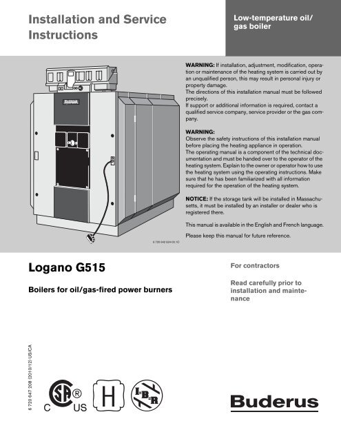
Installation and ServiceInstructionsLow-temperature oil/gas boilerWARNING: If installation, adjustment, modification, operationor maintenance of the heating system is carried out byan unqualified person, this may result in personal injury orproperty damage.The directions of this installation manual must be followedprecisely.If support or additional information is required, contact aqualified service company, service provider or the gas company.WARNING:Observe the safety instructions of this installation manualbefore placing the heating appliance in operation.The operating manual is a component of the technical documentationand must be handed over to the operator of theheating system. Explain to the owner or operator how to usethe heating system using the operating instructions. Makesure that he has been familiarized with all informationrequired for the operation of the heating system.NOTICE: If the storage tank will be installed in Massachusetts,it must be installed by an installer or dealer who isregistered there.This manual is available in the English and French language.6 720 642 624-00.1OPlease keep this manual for future reference.Logano G515Boilers for oil/gas-fired power burnersFor contractorsRead carefully prior toinstallation and maintenance6 720 647 208 (2010/12) US/CA
ContentsAbout this manualThe appliance conforms to the basicrequirements of the relevant directives.The conformity has been confirmed.The corresponding documentation and theoriginal Declaration of Conformity are on filewith the manufacturer.This installation and maintenance instructions containimportant information for the safe and proper installation,initial start-up and maintenance of the oil/gas-fired boilerLogano G515.These installation and maintenance instructions aredesigned for specialists, who, due to their vocationaltraining and experience, are knowledgeable in handlingheating systems and oil and gas installations.The oil/gas-fired boiler Logano G515 is available in twovariants (disassembled and assembled).These installation and maintenance instructions explainthe installation and maintenance of both boiler types.Contents1 Guideline to symbols and safety instructions 41.1 Guideline to symbols . . . . . . . . . . . . . . . . . 41.2 Safety instructions . . . . . . . . . . . . . . . . . . . 42 Product description . . . . . . . . . . . . . . . . . . . . . . 62.1 Designated use . . . . . . . . . . . . . . . . . . . . . . 72.2 Operating conditions . . . . . . . . . . . . . . . . . 82.3 Compliance with standards andregulations . . . . . . . . . . . . . . . . . . . . . . . . . . 92.4 Additional regulations for installations inthe Commonwealth of Massachusetts . .103 Specifications . . . . . . . . . . . . . . . . . . . . . . . . . . 114 Scope of delivery . . . . . . . . . . . . . . . . . . . . . . . . 144.1 Logano G515 – Delivery as apre-assembled block . . . . . . . . . . . . . . . . .144.2 Logano G515 – Delivery in loosesections . . . . . . . . . . . . . . . . . . . . . . . . . . .145 Transporting the boiler . . . . . . . . . . . . . . . . . . 146 Positioning the boiler . . . . . . . . . . . . . . . . . . . . 156.1 Tools and auxiliary materials . . . . . . . . . . 156.1.1 Boiler assembly tool size 2.2 . . . . . . . . . . 156.1.2 Boiler assembly tool size 2.3(complete in the toolbox) . . . . . . . . . . . . .166.2 Recommended wall clearances . . . . . . . . 166.3 Installing the boiler on a boiler base orfoundation . . . . . . . . . . . . . . . . . . . . . . . . . .172Logano G515 - Subject to technical modifications
Contents7 Boiler block assembly . . . . . . . . . . . . . . . . . . . 187.1 Assembly of a boiler block from sections 187.2 Joining the boiler block assembly(delivery as loose sections) . . . . . . . . . . . .197.3 Setting up the boiler block –(assembled block) . . . . . . . . . . . . . . . . . . .247.4 Inserting the supply pipe (parts crate) . . 247.5 Installing the sensor well . . . . . . . . . . . . . 257.6 Leak test . . . . . . . . . . . . . . . . . . . . . . . . . . 257.6.1 Carrying out leak test . . . . . . . . . . . . . . . . 257.6.2 Sealing leaks . . . . . . . . . . . . . . . . . . . . . . . 267.7 Boiler water connections . . . . . . . . . . . . . 267.8 Installing draft diverter, baffles andburner door . . . . . . . . . . . . . . . . . . . . . . . . .277.8.1 Positioning the draft diverter . . . . . . . . . . 277.8.2 Screwing cleanout cover onto rearsection . . . . . . . . . . . . . . . . . . . . . . . . . . . .287.8.3 Fitting the burner door . . . . . . . . . . . . . . . 287.8.4 Hot gas check plates on front section . . 297.8.5 Insert the flue gas baffle plates . . . . . . . . 297.9 Installation of the boiler jacket . . . . . . . . . 307.9.1 Mount the brackets . . . . . . . . . . . . . . . . . . 307.9.2 Fitting the profile rails . . . . . . . . . . . . . . . . 317.9.3 Fitting the thermal insulation . . . . . . . . . . 327.9.4 Fitting side panels and top covers . . . . . 358 Connecting the boiler on the flue gas side . 398.1 Fitting the vent pipe sealing collar(accessory) . . . . . . . . . . . . . . . . . . . . . . . . .398.2 Installing a flue gas temperature sensor(accessory) . . . . . . . . . . . . . . . . . . . . . . . . .3911 System start-up . . . . . . . . . . . . . . . . . . . . . . . . . 4311.1 Filling the system . . . . . . . . . . . . . . . . . . . . 4311.2 Commissioning the system . . . . . . . . . . . . 4411.3 Start up the control panel . . . . . . . . . . . . . 4411.4 Initial burner start-up . . . . . . . . . . . . . . . . . 4411.5 Raising flue gas temperature . . . . . . . . . . 4411.5.1 Removing heat exchanger baffles . . . . . . 4411.5.2 Removing hot gas check plates . . . . . . . . 4511.5.3 Increasing the flue gas temperatureslightly . . . . . . . . . . . . . . . . . . . . . . . . . . . . 4511.6 Commissioning log . . . . . . . . . . . . . . . . . . 4612 Shutting down the system . . . . . . . . . . . . . . . 4712.1 Shutting down the heating system viathe control panel . . . . . . . . . . . . . . . . . . . . 4712.2 Shutting down the system in anemergency . . . . . . . . . . . . . . . . . . . . . . . . 4713 System inspection and maintenance . . . . . . 4813.1 General information . . . . . . . . . . . . . . . . . . 4813.2 Why is regular maintenance important? . 4813.3 Cleaning the boiler with cleaningbrushes . . . . . . . . . . . . . . . . . . . . . . . . . . . 4813.4 Wet-cleaning the boiler . . . . . . . . . . . . . . . 5013.5 Checking the operating pressure . . . . . . . 5113.6 Filling with boiler water and purging thesystem . . . . . . . . . . . . . . . . . . . . . . . . . . . . 5113.7 Inspection and maintenance logs . . . . . . 5214 Troubleshooting burner faults . . . . . . . . . . . . 569 Installing the control panel . . . . . . . . . . . . . . . 409.1 Installing the control panel . . . . . . . . . . . . 409.2 Fitting temperature sensor assembly andburner cable . . . . . . . . . . . . . . . . . . . . . . . .4015 Spare Parts . . . . . . . . . . . . . . . . . . . . . . . . . . . . 57Index . . . . . . . . . . . . . . . . . . . . . . . . . . . . . . . . . . 7510 Mounting the burner . . . . . . . . . . . . . . . . . . . . . 42Appendix . . . . . . . . . . . . . . . . . . . . . . . . . . . . . . 76Logano G515 - Subject to technical modifications 3
1 Guideline to symbols and safety instructions1 Guideline to symbols and safety instructions1.1 Guideline to symbolsWarningsSignal words at the beginning of a warning are used toindicate the type and seriousness of the ensuing risk ifmeasures for minimizing damage are not taken.• NOTICE indicates that damage to property may occur.• CAUTION indicates possible minor to mediumpersonal injury.• WARNING indicates possible severe personal injury.• DANGER indicates a potential for loss of life.Important InformationAdditional symbolsSymbolBWarnings are indicated in the text by awarning triangle and a gray background.In case of danger from electric shock, theexclamation point on the warning triangle isreplaced with a flash.Important information neither indicatingpersonal injury nor damage to property aremarked with this symbol. They are separatedby lines above and below the text.ExplanationSequence of stepsCross-reference to other points in thisdocument or to other documents• Listing/list entryTab. 1– Listing/list entry (2nd level)1.2 Safety instructionsDanger from failing to consider your own safety inan emergency such as a fireB Never risk your own life. Your own safety must alwaystake the highest priority.Risk due to oil leaksB When using oil as the fuel, national regulations hold theoperator responsible for immediately asking aspecialist contractor to remedy oil leaks the momentthey are discovered.If you smell gasB Close the gas shut-off valve.B If you hear gas escaping, evacuate the affected areaimmediately.B Open the windows.B Do not operate any electrical switches or equipmentsuch as telephones, power plugs and doorbells.B Extinguish all open flames.B Do not smoke.Do not use lighters.B Warn all occupants of the building, but do not ringdoorbells.B Call your gas utility company and your local heatingcontractor from outside the building. If necessary,notify police or the fire department.If you smell flue gasB Switch OFF the appliance.B Open windows and doors.B Inform a trained and certified heating contractor.Danger of electric shock when the control panel isopenB Always de-energize the connection before working onelectrical parts (circuit breaker).B Take provisions against unintentional reconnection.Danger of poisoning from flue gas if supply ofcombustion air is insufficientB Safeguard supply of combustion air.B Do not cover or reduce the size of ventilation openingsin doors, windows and walls.B Safeguard sufficient supply of combustion air also forappliances installed at a later date, e.g. kitchen exhaustfans, clothes dryers, and air conditioning units with ventto the outside.4Logano G515 - Subject to technical modifications
Guideline to symbols and safety instructions1B Never operate the appliance if the supply ofcombustion air is insufficient.Combustion air / room airTo prevent corrosion, keep the supply of combustion air /room air free of corrosive substances (e.g. halogenatedhydrocarbons that contain chlorine or fluorinecompounds).Danger of explosion of flammable gases.B Only employ a trained and certified contractor to carryout work on the gas train.Explosive and easily combustible materialsNever use or store easily combustible materials (paper,thinners, paints, etc.) near the appliance.Installation, conversionOnly have the appliance installed or modified by a trainedand certified heating contractor.Never modify any parts that carry flue gas.Never close the outlet of safety valves. Water may beexpelled from any safety valve during heat-up.Inspection and maintenanceThe operator is responsible for safety and environmentalcompliance of the heating system.Sign a maintenance and inspection contract with atrained and certified contractor, covering an annualinspection and demand-dependent maintenance. Thisguarantees high efficiency and environmentally soundcombustion.Instructing the customerB Instruct customers about the functions and operationof the appliance.B Inform the customer that they must not carry out anymodifications or repairs.B Only use the boiler for its intended purpose and onlywhen it is in working order.DisposalB Dispose of packaging in an environmentallyresponsible manner.B All heating system components that have to bereplaced should be disposed of in environmentallyresponsiblemanner at an authorized disposal site.Other important informationB If the system overheats or the gas supply does not shutoff, do not switch off or disconnect the power supply tothe pump. Instead, shut off the gas supply somewhereelse separate from the heating system.Logano G515 - Subject to technical modifications 5
2 Product description2 Product description4231Fig. 1Oil/gas-fired boiler Logano G5151 Boiler shell (jacket)2 Thermal insulation3 Boiler heat exchanger4 Control panel assembly16 720 642 624-01.1ONOTICE: Risk of system damage from use ofincorrect burner.B Only use burners that meet the technicalrequirements of the oil/gas-fired boilerLogano G515 ( Chapter 3, page 11).The main components of the Logano G515 oil/gas-firedboiler are:• Boiler block ( Fig. 1, [3]) The boiler heat exchangertransfers the heat generated by the burner to the boilerwater.• Boiler shell (jacket, ( Fig. 1 [1] and Fig. 2, [1]),thermal insulation ( Fig. 1, [2]). The boiler jacket andthermal insulation minimize energy loss.• Control panel ( Fig. 1, [4]). The control panel isdesigned to monitor and control all electricalcomponents of the Logano G515 oil/gas-fired boiler.Observe all standards and guidelinesapplicable to the installation and operation ofthe system in your country.Please observe the information on the boilerrating plate.1To prevent boiler contamination, werecommend installing a dirt trap in the watersystem.11As a basic rule, flush existing systems beforeconnecting the boiler.Install a desludging unit in the boiler return toprevent damage to the boiler.6 720 642 624-02.1OFig. 2Front jacket1 Boiler shell (jacket)The Logano G515 oil/gas-fired boiler is supplied with orwithout a burner You can obtain undrilled or predrilledburner plates (hole pattern depends on burner) asaccessories from <strong>Buderus</strong>.The predrilled burner plate is included in the scope ofdelivery for the Logano G515 with oil or gas-fired fanassistedburners.6Logano G515 - Subject to technical modifications
Product description2FuelsLogano G515 Heating oil Liquid propane (LPG) Natural gas (NG)RemarksThe Logano G515 boiler can be operated with the specified fuels. Select a burner suitable for use with thefuels specified for the Logano G515 boiler.The output figures shown in the Tab. “Technical Data” are nominal power figures.Carry out maintenance and cleaning procedures annually. Check that the entire system is functioningcorrectly.Immediately remedy faults.Tab. 2If heating oil is used, shorter maintenance intervals may be necessary depending on the operating time.2.1 Designated useThe Logano G515 oil/gas-fired boilers have beendesigned for the heating of water.The Logano G515 can be operated with oil, gas, andcombination burners. For a list of the approved burners,please contact Bosch Thermotechnology Corp.This boiler can be operated with an aquastat, theLogamatic 4000, and other control systems.Logano G515 - Subject to technical modifications 7
2 Product description2.2 Operating conditionsThermostream technology is a unique feature of <strong>Buderus</strong>cast iron boilers. Return water is preheated and mixedwithin the boiler before it comes in contact with theheating surface of the combustion chamber. TheThermostream technology ensures there is an eventemperature distribution in the boiler and avoidscondensate forming within the combustion chamber. Thisunique feature reduces thermal stress, the main cause offailure of traditional cast iron boilers. The advantage of thistechnology is the maintenance of the minimum operatingtemperature of the boiler ( Tab. 3); this makes theinstallation of a shunt pump unnecessary. This way, thecosts for the pump itself and its power consumption, aswell as possible failure costs are saved. The minimumboiler operating temperature as shown in the table belowmust be reached within 10 minutes and then bemaintained while the burner is running.Minimum flow rateThis operating condition can be easily achieved by thecontrols monitoring the boiler temperature and reducingthe flow rate through the boiler until the requiredtemperature is reached. This is then maintained bycontinuing to control flow based on the boiler watertemperature. The controls can reduce the flow rate byclosing the valves on the mixed heating circuits,modulating the boiler primary pumps or by closing themotorized butterfly valves or by having a motorized valvein the boiler return on a single boiler installation. The<strong>Buderus</strong> 4000 series control panel can manage thisprocess or it can be completed by the BMS.If it is not possible for the control panel to regulate theflow sufficiently to meet this operating condition, then ashunt pump circuit must be fitted to avoid the type ofthermal stress that all boilers would experience in theseconditions. This shunt pump circuit can be controlledeither with a <strong>Buderus</strong> 4000 control panel or with a thirdpartycontroller. Failure to ensure that the operatingcondition is maintained may lead to thermal stress in theboiler and eventual failure of the sections which would beoutside the scope of the warranty.Control of all heatingzones with <strong>Buderus</strong> 4000Minimum return temperature °F ( °C) noneMinimum operating temperature oil boiler 1)°F ( °C) 122 (50)noneExternal controls (BMS) orAquastat controlMinimum operating temperature gas boiler 1) °F ( °C) 122 (50) 140 (60)Maximum supply temperature °F ( °C) 212 2) /248 3) (100 2) /120 3) )Maximum operating pressure PSI (bar) 87 (6)Time constant of the temperature controller sec 40Time constant of the monitor/limiter sec 40Tab. 31) This temperature has to be reached within ten minutes of the burner starting and has to be maintained whilst the burner is firing.2) The maximum supply temperature is 212 °F (100 °C), if the boiler is operated as hot water boiler.3) The maximum supply temperature is 248 °F (120 °C), if the boiler is operated as a hot water generator.8Logano G515 - Subject to technical modifications
Product description22.3 Compliance with standards andregulationsInstallation and operation of the system must comply withall applicable codes, regulations and statutoryrequirements.Installation, connection of the fuel supply and flueconnector, commissioning, connection of the electricalpower supply, servicing and repair may only be carried outby trained and certified heating contractor. Onlyregistered gas fitters may carry out work on the gas train.The system must be cleaned and serviced once a year.The operation of the complete system must be tested atthe same time. Any faults must be corrected immediately.The design and mode of operation of this boiler complywith the American National Standard ANSI Z21.13/CSA4.9, latest edition for Gas Fired Low Pressure Steamand Hot Water Boilers.Other confirmed approvals and certifications areindicated by labels on the boiler.The heat exchanger has been designed and certified inaccordance with the ASME Boiler and Vessel Code,Section IV.Installation of the wall mounted condensing gas boilermust comply with all applicable codes and regulationsimposed by the national, Federal or local authorities andbodies. If no specific requirements are defined, in theUSA, the latest edition of the National Fuel Gas CodeANSI Z223.1/NFPA 54 applies. In Canada, installationmust comply in all respects with the latest edition of theInstallation Code for Gas Burning Appliances andEquipment, CAN/CSA-B.149 and the applicable localregulations and requirements for the appliance category.The relevant authorities and regulatory bodies must beinformed before installation starts.Where required by local regulations, the system mustcomply with the American Society of MechanicalEngineers Safety Code for Controls and Safety Devicesfor Automatically Fired Boilers (ASME CSD-1).The hot water distribution system must comply with allapplicable codes and regulations. When replacing anexisting boiler, it is important to check the condition of theentire hot water distribution system to ensure safeoperation.In the Commonwealth of Massachusetts, this appliancemust be installed by a licensed plumber and gas fitter.Valves external to the boiler must be fitted with T-handlesand condensate piping must be installed in accordancewith the State Plumbing Code.Logano G515 - Subject to technical modifications 9
2 Product description2.4 Additional regulations forinstallations in the Commonwealthof Massachusetts(a) For all side wall horizontally vented gas fueledequipment installed in every dwelling, building or structureused in whole or in part for residential purposes, includingthose owned or operated by the Commonwealth andwhere the side wall exhaust vent termination is less thanseven (7) feet above finished grade in the area of theventing, including but not limited to decks and porches,the following requirements shall be satisfied:• INSTALLATION OF CARBON MONOXIDEDETECTORS. At the time of installation of the side wallhorizontal vented gas fueled equipment, the installingplumber or gasfitter shall observe that a hard wiredcarbon monoxide detector with an alarm and batteryback-up is installed on the floor level where the gasequipment is to be installed. In addition, the installingplumber or gasfitter shall observe that a batteryoperated or hard wired carbon monoxide detector withan alarm is installed on each additional level of thedwelling, building or structure served by the side wallhorizontal vented gas fueled equipment. It shall be theresponsibility of the property owner to secure theservices of qualified licensed professionals for theinstallation of hard wired carbon monoxide detectors.– In the event that the side wall horizontally vented gasfueled equipment is installed in a crawl space or anattic, the hard wired carbon monoxide detector withalarm and battery back-up may be installed on thenext adjacent floor level.– In the event that the requirements of this subdivisioncannot be met at the time of completion ofinstallation, the owner shall have a period of thirty(30) days to comply with the above requirements;provided, however, that during said thirty (30) dayperiod, a battery operated carbon monoxidedetector with an alarm shall be installed.• APPROVED CARBON MONOXIDE DETECTORS.Each carbon monoxide detector as required inaccordance with the above provisions shall complywith NPA 720 and be ANSI/UL 2034 listed and IAScertified.• SIGNAGE. A metal or plastic identification plate shallbe permanently mounted to the exterior of the buildingat a minimum height of eight (8) feet above gradedirectly in line with the exhaust vent terminal for thehorizontally vented gas fueled heating appliance orequipment. The sign shall read, in print size no less thanone-half (½) inch in size, “GAS VENT DIRECTLYBELOW. KEEP CLEAR OF ALL OBSTRUCTIONS”.• INSPECTION. The state or local gas inspector of theside wall horizontally vented gas fueled equipment shallnot approve the installation unless, upon inspections,the inspector observes carbon monoxide detectorsand signage installed in accordance with theprovisions of 248 CRM 5.08(2)(a) 1 through 4.(b) EXEMPTIONS: The following equipment is exemptfrom 248 CRM 5.08(2)(a) 1 through 4:• The equipment listed in Section 10 entitled“Equipment Not Required To Be Vented” in the mostcurrent edition of NFPA 54 as adopted by the board;and• Product Approved side wall horizontally vented gasfueled equipment installed in a room or structureseparate from the dwelling, building or structure usedin whole or in part for residential purposes.(c) MANUFACTURERS REQUIREMENTS - GASEQUIPMENT VENTING SYSTEM REQUIRED. When themanufacturer of Product Approved side wall horizontallymounted gas equipment provides a venting systemdesign or venting system components with theequipment, the instructions provided by the manufacturerfor the installation of the equipment and venting shallinclude:• Detailed instructions for the installation of the ventingsystem or the venting system components; and• A complete parts list for the venting system design orventing system.(d) MANUFACTURERS REQUIREMENTS - GASEQUIPMENT VENTING SYSTEM NOT PROVIDED.When the manufacturer of Product Approved side wallhorizontally vented gas fueled equipment does notprovide the parts for the venting of flue gases, butidentifies “special venting systems”, the followingrequirements shall be satisfied by the manufacturer:• The referenced “special venting systems” shall beincluded with the appliance or equipment installationinstructions; and• The “special venting systems” shall be ProductApproved by the Board, and the instructions for thatsystem shall include a parts list and detailed installationinstructions.(e) A copy of all instructions for all Product Approved sidewall horizontally vented gas fueled equipment, all ventinginstructions, all parts lists for venting instructions, and/orventing design instructions shall remain with theappliance or equipment at the completion of theinstallation.10Logano G515 - Subject to technical modifications
Specifications33 SpecificationsThe technical data provides information about the outputprofile of the Logano G515.28-37/64"(980 mm)2-23/64" 2 23/64"(60 mm)4-31/64" 4 (114 mm)23-1/16"(586 mm) 52-11/64"(1325 mm)61-1/4"1/4"(1556 mm)51-49/64"(1315 mm)VK4-1/2" 4 (115 mm)44-3/32"(1120 mm)23-1/32"(585 mm)RKØ ≤ 10-5/8"(270 mm)3-5/32" 3 (80 mm)EL10"(250 mm)6 720 642 623-01.1oFig. 3 Technical data for Logano G515 (dimensions in inches (mm))EL Drain valve (Rp ¾) 1)L K Boiler heat exchanger lengthL Overall boiler lengthRK Return connection on the boiler 2)VK Supply connection on the boiler 3)L KL1) With the drain valve (EL), you may only drain the system, not fill it.2) The filling of the boiler and the system must be undertaken on aseparate connector on the return line.3) The flange corresponds to the order reduced to 212 (DN100), 176(DN80) or 149 (DN65).Logano G515 - Subject to technical modifications 11
3 SpecificationsLogano G515Boiler capacity Unit 240 295 350 400 455 510Number of boiler sections – 7 8 9 10 11 12Nominal outputMBH685.8 -818.9822.3 -1.006.61.010.0 -1.194.21.197.7 -1.364.91.368.3 -1.552.51.555.9 -1.74.2(kW )(201 – 240)(241 – 295)(296 – 350)(351 – 400)(401 – 455)(456 – 510)Combustion outputMBH735.7 -886.1879.7 -1.088.51.080.3 -1.286.71.278.2 -1.465.91.461.8 -1.669.21.665.8 -1.869.2(kW)(215.6 –259.7)(257.8 –319.0)(316.6 –377.1)(374.6 –429.6)(428.4 –489.2)(488.2 –547.8)Boiler overall length (L)inches62 – 7/3268 – 29/3275 – 19/3282 – 9/3288 – 31/3295 – 23/32(mm)(1580)(1750)(1920)(2090)(2260)(2430)Boiler block length (L K )inches53 – 35/6460 – 15/6466 – 59/6473 – 5/880 – 5/1687(mm)(1360)(1530)(1700)(1870)(2040)(2210)Fitting clearance, boilersection(width × height × depth)Fitting clearance, boilerblock(width × height × length)inches(mm)inches(mm)32 7/8 × 51 49/64 × 6 45/64(835 × 1315 × 170)32 7/8 × 51 49/64 × L K(835 × 1315 × L K )Combustion chamberlengthinches(mm)45 – 55/64(1165)52 – 9/16(1335)59 – 1/4(1505)65 – 15/16(1675)72 – 41/64(1845)79 – 21/64(2015)Combustion chamberdiameterBurner door thicknessinches(mm)inches20 – 17/64(515)5 – 19/32(mm)(142)Weight, net 1)lb.2.803.1533.5063.8654.1894.542(kg)(1270)(1430)(1590)(1753)(1900)(2060)Boiler water contentgal.68.277.787.296.7106.2115.7(l)(258)(294)(330)(366)(402)(438)Gas capacitygal.111.2128.6145.5162.7179.9196.8(l)(421)(487)(551)(616)(681)(745)Flue gas temperature,partial load (60%)°F(°C)281(138)281(138)284(140)265(129)266(130)284(140)Flue gas temperature, fullload°F(°C)328 – 362(164 – 183)322 – 362(161 – 183)322 – 351(161 – 177)315 – 340(157 – 171)319 – 342(159 – 172)328 – 346(164 – 174)Tab. 412Logano G515 - Subject to technical modifications
Specifications3Logano G515Boiler capacity Unit 240 295 350 400 455 510Flue gas mass flow rate, lb./s 0.143 0.176 0.207 0.238 0.271 0.302oil, partial load (60%)(kg/s) (0.065) (0.080) (0.094) (0.108) (0.123) (0.137)Flue gas mass flow rateoil, full load 2)lb./s0.203 –0.2430.241 –0.2980.296 –0.3530.351 –0.4010.401 –0.4590.457 –0.514(kg/s)(0.092 –0.11)(0.109 –0.135)(0.134 –0.16)(0.159 –0.182)(0.182 –0.208)(0.207 –0.233)Flue gas mass flow rate,gas, partial load (60%)lb./s(kg/s)0.143(0.065)0.176(0.080)00.209(0.095)0.238(0.108)0.271(0.123)0.304(0.138)Flue gas mass flow, gas,full load 2)lb./s(kg/s)0.203 –0.245(0.092 –0.111)0.243 –0.300(0.11 –0.136)0.298 –0.355(0.135 –0.161)0.353 –0.403(0.16 –0.183)0.403 –0.459(0.183 –0.208)0.459 –0.233(0.208 –0.233)CO 2 content, oil % 13CO 2 content, gas % 10Required draftPSI(Pa)0(0)Flue gas resistancePSI––––––(mbar)(0.5 – 0.6)(1.0 – 1.4)(1.1 – 1.6)(2.1 – 2.9)(2.5 – 3.3)(2.4 – 3.1)Maximum permissible °Fsupply temperature 3) (°C)248(120)Maximum permissibleoperating pressurePSI(bar)87(6)Tab. 41) Weight with packaging approx. 6–8% higher.2) The details relate to the upper and lower rated output range.3) Safety limit (high limit safety cut-out). Maximum possible supply temperature = safety limit (STB) – 32 °F (–18 K).Example: Safety limit (STB): = 212 °F (100 °C), max. possible supply temperature = 212–32 = 180 °F (100–18 = 82 °C).Logano G515 - Subject to technical modifications 13
4 Scope of delivery4 Scope of deliveryThe Logano G515 can be delivered either as a preassembledblock or in loose sections.B Check that the packaging is undamaged on delivery.B Check that the delivery is complete.4.1 Logano G515 – Delivery as a preassembledblockComponent Qty PackagingBoiler block with burner doorand draft diverterAssembly components(longitudinal rails and supplypipe)Jacket Pack A, B, C (accordingto boiler rating)1 Pallet1 Box1– 3 CartonsThermal insulation 1 PU bagTab. 54.2 Logano G515 – Delivery in loosesectionsComponent Qty PackagingFront and rear section as wellas burner doorIntermediate sections –(depending on boiler size)1 Pallet1– 2 PalletFittings 1 BoxExhaust manifold 1 BoxTie rods 1 bundleAssembly components(longitudinal rails and supplypipe)1 Box5 Transporting the boilerUse suitable equipment to transport the individual boilersections (delivery as loose sections) and other individualparts.WARNING: Risk of injury from improperlysecured boiler sections.B Use only suitable means of transportationwhen handling the boiler sections, e.g. aheavy duty hand truck.B Secure the individual boiler sections toprevent them from sliding off duringtransport.NOTICE: Risk of system damage fromimpacts.B The standard delivery of the Logano G515oil/gas-fired boiler contains componentsthat are sensitive to shock.B During handling protect all electronic andother components against impact.B Please observe the transport instructionson the packaging.NOTICE: Risk of system damage fromcontamination.B If you intend to keep the boiler in storageonce it has been assembled, observe thefollowing:B Protect the boiler connections againstcontamination by sealing them off orcovering them.Dispose of packaging in an environmentallyresponsible manner.Jacket Pack A, B, C (accordingto boiler rating)1– 3 CartonsThermal insulation 1 PU bagTab. 614Logano G515 - Subject to technical modifications
Positioning the boiler66 Positioning the boilerThis chapter describes how to properly position theLogano G515.NOTICE: Risk of system damage fromfreezing.B Install the system in a room free from thedanger of freezing.6.1.1 Boiler assembly tool size 2.24 5L 1L 26.1 Tools and auxiliary materialsThe following tools and auxiliary materials are required forthe boiler assembly (the listed items must be provided bythe installer):• Boiler assembly tool 2.2 ( Fig. 4, page 15) or 2.3( Fig. 5, page 16)• Boiler block support for fitting the boiler sectionstogether• Steel hammer and wooden or rubber mallet• Half-round bastard file• Screwdriver (Philips and flat head)• Flat chisel• Metric wrenches• Support wedge, flat iron• Cleaning rags and cloth• Fine emery cloth• Wire brush• 3-in-1 oil• Solvent (gasoline, mineral spirits)• Spirit level, tape measure, chalk, straight edge• Blanking flange with vent facility (for pressure test)Fig. 4 Boiler assembly tool size 2.21 Mating flange2 Additional flange3 Compression unit4 Tie rod5 Extension6 Dowel pin (size 2.2)L 1 85" (2160 mm)L 2 23 – 5/8" (600 mm)BoilersectionsAssemblytool(s) perboiler hubExtensionpiece perboiler hub7– 10 1 011 – 12 1 1Tab. 73 2 166 720 642 623-02.1oLength (total)in inches(mm)85 – 3/64(2160)108 – 21/32(2760)For the correct arrangement of the flangeduring assembly, refer to page 22.Logano G515 - Subject to technical modifications 15
6 Positioning the boiler6.1.2 Boiler assembly tool size 2.3 (complete inthe toolbox)6.2 Recommended wall clearances4 5L 1≥ 15-3/4"(400 mm)38-37/64"37/64"(980 mm)35-1/2"(~ 900 mm)63 2 16 720 642 623-03.1oFig. 5 Boiler assembly tool size 2.31 Mating flange2 Additional flange3 Compression unit4 Tie rod5 Extension6 Wedge (size 2.3)L 1 121– 1/4" (3080 mm)L 2 31 – 1/2" (800 mm)Fig. 6L 2L 2Observe the recommended wall clearancesAB + 4"L K(AB+100 mm)ABAInstallation room with boiler6 720 642 623-04.1oBoilersectionsAssemblytool(s) perboiler hubExtensionpiece perboiler hub7– 12 1 3Tab. 8Length (total)in inches(mm)121 – 1/4(3080)For the correct arrangement of the flangeduring assembly, refer to page 22.for complete opening of the burner door, forboiler installation and for cleaning andmaintenance ( Fig. 6 and Tab. 9).The burner door can be right or left hung/opening (theboiler is always supplied with the door attached on theright).When installing your boiler maintain the recommendedminimum dimensions. Select the recommendedclearances between wall and boiler for easy access forinstallation, maintenance and service work.The wall clearance on the hinge side must be at least theburner projection (AB). A distance of AB + 3 – 15/16"(AB + 100 mm) from the wall is recommended.16Logano G515 - Subject to technical modifications
Positioning the boiler6Boiler capacity Clearance A in inches (mm)MBH (kW)Boilersections Recommended minimum7– 966 –15/16" 39 – 3/8"(1700) (1000)819 – 1.194(240 – 350)1,365 – 1,740(400 – 510)Tab. 910 – 1286 – 39/64"(2200)39 – 3/8"(1000)If you do not observe the recommended minimumclearance ( Fig. 6), you will not be able to use thecleaning kit (accessory). Alternatively, shorter cleaningdevices or wet cleaning may be used. Alternatively shortercleaning devices or wet cleaning may be used.6.3 Installing the boiler on a boiler baseor foundationensure that the boiler sections can slide when the boileris installed ( Fig. 7 and Tab. 10).It is advisable to place the boiler on a 2 – 4 inch (50 –80 mm) tall base ( Fig. 7, [1]). The installation area mustbe completely flat and level. The front edge of the boilershould be flush with the edge of the base.Number ofboiler sectionsWhen building the bases, consider to whichside the burner swings out (left or right-handburner door stop ( Fig. 6, page 16).L1(base) in inch(mm)L2(steel section) ininch (mm)7 53 – 35/64 (1360) 46 – 27/32 (1190)8 60 – 15/64 (1530) 53 – 35/64 (1360)9 66 – 59/64 (1700) 60 – 15/64 (1530)2...4"(850 mm)L 2(~ 50...80 mm)33-1/2"110 73 – 5/8 (1870) 66 – 59/64 (1700)11 80 – 5/16 (2040) 73 – 5/8 (1870)12 87 (2210) 80 – 5/16 (2040)Tab. 10L 1Fig. 74"(100 mm)21-1/4"1/4"(540 mm)3-1/2" 3 (~ 90 mm)6 720 642 623-05.1oBase dimensions (dimensions in inches (mm))A silencing boiler base is available as anaccessory from <strong>Buderus</strong>.If this boiler base is not used, a concrete foundation canbe constructed on-site. When building the base, a3 – 15/16 × 1 – 31/32 × 5/16 inches(100 × 50 × 8 mm) steel angle or 3 – 15/16 × 13/64inches (100 × 5 mm) steel flat should be incorporated, toLogano G515 - Subject to technical modifications 17
7 Boiler block assembly7 Boiler block assemblyWARNING: Risk of injury from improperlysecured boiler sections.B Use only suitable means of transportationwhen handling the boiler sections, e.g. aheavy duty hand truck with strap or aheavy duty hand truck.B Secure the individual boiler sections toprevent them from sliding off duringtransport.7.1 Assembly of a boiler block fromsectionsWARNING: Risk of injury from inadequatelysecured boiler sections.B Secure boiler sections during assemblyand take measures to prevent them fromtipping over. The installation aid(accessory) is available from <strong>Buderus</strong> onrequest.5 67483219107Fig. 8Boiler heat exchanger1 Boiler base or foundation2 Exhaust manifold3 Rear section4 Return connection5 Supply connection6 Intermediate section7 Tie rod8 Sequence of installation9 Front section10 Burner door with burner plate6 720 642 623-06.1oDepending on the type of delivery, we distinguishbetween delivery as disassembled sections and as readyassembled block. When delivered as a block, the boilersections are already fully assembled and checked forleaks prior to delivery. If the assembled boiler is too largeor too heavy to be brought to its final installation locationin the building, delivery of the disassembled boiler insections offers a solution.For the further installation of a pre-assembled boiler block,see Chapter 7.3, page 24.6 720 642 621-04.1oFig. 9 Rear sectionThe boiler block is always installed starting from the rearwith the rear section ( Fig. 8, [3], page 18) and workingtoward the front. The front section ( Fig. 8, [9],page 18) is always fitted last.Observe the directional arrows ( Fig. 8, [8]) duringassembly and carry this out in accordance with thefollowing instructions and illustrations.18Logano G515 - Subject to technical modifications
Boiler block assembly77.2 Joining the boiler block assembly(delivery as loose sections)Remove nuts and washers from the studs on the hubs ofthe boiler sections before attaching the rear section andfront section.B Set up the rear section and secure with the installationaid to prevent it from tipping ( Fig. 11 and Fig. 9 andseparate installation instructions for installation aid).If you are using the installation aid, you willneed to remove the cleaning access coverbefore you can attach it to the rear section.B Unscrew cleanout cover on rear section ( Fig. 10, [1and 2]).6 720 642 623-09.1o1Fig. 11 Fastening the installation aidB File down any burrs on the hubs ( Fig. 12).B Clean the packing grooves where required using a wirebrush and cloth ( Fig. 13, [3]).26 720 642 623-08.1oFig. 10 Removing the cleanout cover.6 720 642 621-05.1oFig. 12 Remove burrsLogano G515 - Subject to technical modifications 19
7 Boiler block assemblyWARNING: Danger of fire from combustiblecleaning agents.B When using solvents, avoid open flames,ambers, and sparks.B Please observe the safety instructionsregarding any solvents used.1B Clean the hub sealing faces ( Fig. 13, [1 and 2]) witha rag soaked in solvents or gasoline.WARNING: Health hazard from noxiousvapors released during material handling.B Ensure adequate ventilation of theinstallation area.B Please note the handling and safetyinstructions of the product used.26 720 642 621-07.1oB Evenly coat the hub sealing faces with sealant.Fig. 14 Driving nipples homeThe packing grooves ( Fig. 15, [1]) must be clean anddry to enable the sealant rope to adhere properly.B Coat the packing grooves with adhesive (primer)13126 720 642 621-06.1oFig. 13 Prepare packing grooves and hubsThe next step involves preparing the nipples that willeventually seal the boiler sections.B Clean nipple with a rag soaked in solvents or gasolineand coat evenly with sealant.B Insert the nipple straight into the upper (Sz. 4.181.70)and lower (Sz. 1, 82/50) hub of the rear section andpound home securely with alternate heavy blows. Oncepounded in, the upper nipple ( Fig. 14, [1]) mustprotrude approx. 1 – 49/64 inches (45 mm) and thelower nipple approx. 1 – 3/8 inches (35 mm) out of thecorresponding hubs.B Remove any burrs with a file.6 720 642 621-08.1oFig. 15 Coat the packing grooves with adhesive(primer)20Logano G515 - Subject to technical modifications
Boiler block assembly7B Insert the flexible sealant rope ( Fig. 16, [2]) on thefront of the rear section, starting around the upper hub,into the packing grooves ( Fig. 16, [1]) and press inlightly. At the butt joints, overlap the sealant rope byapprox. 3/4" (20 mm) and press firmly together.B Unroll the required length of sealant rope from thespool supplied.B Peel the backing paper from the sealant rope wheninserting into the packing groove (do not stretch).1216 720 642 623-15.1oFig. 17 Preparing the intermediate section2To make installation easier, place the boilersection to be fitted onto the nipple on theupper hub first. Once this has been done, theboiler section can be aligned with the lowerhub.6 720 642 621-09.1oFig. 16 Inserting sealant ropePreparation of the first intermediate section:B File down any burrs on the hubs ( Fig. 12, page 19).The packing springs must be clean and dry. Clean ifnecessary.B Clean the hub sealing faces with a rag soaked insolvents or gasoline.B Evenly coat the hub sealing faces with sealant( Fig. 17, [1]).B Coat the packing springs with primer ( Fig. 17, [2]).The directional arrow ( Fig. 18, [3]) must point towardthe rear.B Position the intermediate section so that the upper andlower hubs ( Fig. 18, [2 and 4]) fit onto the nipples inthe rear section.B Drive first intermediate section onto the rear sectionusing a wooden or a rubber mallet ( Fig. 18, [1]).12346 720 642 621-11.1oFig. 18 Pound intermediate section in placeLogano G515 - Subject to technical modifications 21
7 Boiler block assemblyBefore the nipples are inserted in the nextintermediate section, the part-assembledboiler block must be compressed using theboiler assembly tool.NOTICE: The boiler can be damaged bypulling the boiler sections togetherincorrectly or from excessive compression.B Ensure that the nipples are positionedstraight in the boiler hubs after beingpounded in and that they have not beencompromised.B Never compress more than one nipplejoint at a time.B Stop compressing the sections when theboiler hubs meet.NOTICE: Assembly tool damage from loosescrew connections of the tie rods.B Always check the tie rods before each useand retighten as necessary. The tie rod iscorrectly positioned if it is fully insertedand no threads are showing ( Fig. 19,[2]).B Always keep the threads ( Fig. 19, [1])clean. Dirty threads may damage theassembly tool during assembly.CAUTION: Danger of accident from materialfatigue. Improperly used or poorly maintainedassembly tools may fail.B Never work directly in front of theassembly tool while it is being tensioned.B Ensure that no one is standing in front ofthe assembly tool.Use a size 2.2 or 2.3 boiler assembly tool ( Fig. 4, Fig. 5and Fig. 20 [1 and 2]).B Push pressure flanges ( Fig. 20, [3]) with clampingnuts onto the tie rods ( Fig. 4, page 15 and Fig. 5,[4]).B Push a tie rod through the upper and lower hubs on theboiler.B Push mating flanges onto the tie rods and secure eachwith wedge (dowel pin for assembly tool 2.2).B Hold the tie rod in the center of the boiler hubs andslightly draw together the assembly tools using theclamping nut.B Place ratchet wrench onto clamping nuts andcompress boiler sections by tightening evenly.231146 720 642 621-12.1o26 720 642 623-18.1oFig. 20 Using the boiler assembly toolB Release and remove the boiler assembly tool.B Check nipples are seated correctly.Fig. 19 Boiler assembly tool 2.322Logano G515 - Subject to technical modifications
Boiler block assembly7WARNING: Risk of injury from falling boilersections.B Remove the installation aid first if thepartly-assembled boiler consists of atleast three boiler sections.Fig. 21 shows the rear section with intermediate sectionfitted. The preparations for fitting the next intermediatesection have also been made.The boiler section has been equipped with foot wedgesfor ease of installation ( Fig. 21, [1]).The boiler section foot wedges are also used later for finalleveling of the boiler block.B Level the boiler block vertically and horizontally on thebase/foundation ( see Chapter 6, page 15).B Remove boiler assembly tool.23146 720 642 623-20.1oFig. 22 Fitting the tie rodsThe next step describes the installation of the supply pipe( Chapter 7.4, page 24).16 720 642 623-19.1oFig. 21 Using the boiler section foot wedgesAssemble all other boiler sections as described. The frontsection is fitted last.After the front section is installed, loosen theassembly tool – but do not remove it. Fit thetie rods first.B Insert the tie rods (with spring packs fitted) into thecast lugs on the top left and right, and bottom left andright, next to the boiler hubs ( Fig. 22, [1 to 4]).NOTICE: Damage to system throughexcessively low contact pressure.B Do not compress the spring pack. Onlyuse the spring pack in its original state.B Tighten the nuts hand-tight.B Tighten the nuts on the tie rods 1 to 1½ turns.Logano G515 - Subject to technical modifications 23
7 Boiler block assembly7.3 Setting up the boiler block –(assembled block)DANGER: Risk of fatal injury from fallingobjects.B Provide a suitable means of supportingthe load.B Observe all locally applicableoccupational health & safety regulationsregarding lifting equipment.B Cut the straps ( Fig. 23, [1]).B Remove the pallet prior to positioning the boiler block( Fig. 23, [2]).7.4 Inserting the supply pipe (partscrate)The supply pipe ( Fig. 24, [4]) consists of 2 pieces forboilers with 10 – 12 boiler sections.B Push the flat gasket over the supply pipe ( Fig. 24,[1]).B Push the supply pipe from the front into the top boilerhub.B Close off with flange cover ( Fig. 24, [2]).The supply pipe must be fixed in such a waythat the holes on the supply pipe arepositioned at the correct angle. This ensuresoptimum distribution of water in the area ofthe top boiler hub (Thermostream principle).B Make sure that the cam [3] on the endplate of the supply pipe ( Fig. 24, [3])fits in the notch in the top boiler hub( Fig 24, [5]).3 4 51226 720 642 623-21.1o1Fig. 23 Boiler block on palletB Level the boiler block vertically and horizontally on thebase/impact sound-absorbing base ( Chapter 6.3,page 17). Use the boiler section foot wedges providedfor this purpose.The following pages describe the installation of the supplypipe and sensor well. You must do both irrespective ofwhether the boiler is supplied pre-assembled or inseparate sections.Fig. 24 Installing the supply pipe6 720 642 623-22.1o24Logano G515 - Subject to technical modifications
Boiler block assembly77.5 Installing the sensor wellB Seal and install the sensor well R ¾ from the rear of theboiler (length: 110 mm) into the R ¾ tapped hole of thesupply connection ( Fig. 25, [1]).17.6 Leak testConduct a leak test of the boiler block only when theboiler was delivered disassembled. Pre-assembledsections are leak tested in the factory.For details of assembling the remainder of the boiler if theblock is delivered pre-assembled, see Chapter 10,page 42.7.6.1 Carrying out leak testFig. 25 Fitting the sensor well6 720 642 623-23.1oNOTICE: Risk of system damage fromoverpressure.B Ensure that no pressure, control or safetyequipment is fitted during leak tests.The leak test must be performed with a test pressure of125 psi (8.6 bar). Use a pressure gauge class 1.0 tomeasure the pressure.B Close off lower boiler hub ( Fig. 26, [3]) at the frontand rear. To do this, place corresponding seal( Fig. 26, [1]) on the relevant boiler hub and screwon flange cover with edge length 4 21/64 inches(110 mm). In this case, the flange with the tapped hole(R ¾) for the fill and drain connection ( Fig. 26, [2])is mounted on the rear of the boiler.B Install the on-site fill and drain valve.B Close off supply and return connections (supplyconnection flange with purger valve).1236 720 642 623-24.1oFig. 26 Fitting the flangeB Slowly fill the boiler with water via the fill and drainconnection. While doing this, purge the air from theboiler via the boiler supply connection with purger.Logano G515 - Subject to technical modifications 25
7 Boiler block assembly7.6.2 Sealing leaksB If a hub connection is leaking, first drain the waterthrough the fill/drain valves.B Remove supply pipe.B Undo nuts on tie rods and remove tie rods.B Separate the boiler at the leak location by driving(knocking) in flat wedges or chisels between thesections at the points provided at the top and bottom( Fig. 27, [1 and 2], between the sections).7.7 Boiler water connectionsPlease observe the following information regarding theboiler connection to the system side. These instructionsare important for trouble-free operation.NOTICE: Risk of system damage fromleaking connections.B All pipe connections to the boiler must befree of stress and tension.1NOTICE: System damage from deposits,local overheating, and corrosion.B As a basic rule, clean and flush existingsystems thoroughly before connecting thenew boiler.B Install a desludging unit in the boiler returnto prevent damage to the boiler.Fig. 27 Separating the boiler block26 720 642 623-25.1oThe weld neck flange is fitted to the upper boiler hub( Fig. 28, [3] – return connection) if the return isconnected at a later stage.The weld neck flange and flat gasket are shown( Fig. 28, [4 and 5]).B The supply connection flange ( Fig. 28, [1]) with flatgasket ( Fig. 28, [2]) is required for connecting thesupply at a later stage.B Use new nipples and new sealant rope forreassembly.B Pull the boiler back together and repeatthe leak test.1 2 3 456 720 642 623-26.1oFig. 28 Fitting a flange26Logano G515 - Subject to technical modifications
Boiler block assembly7The boiler supply and return manifolds areincluded in the <strong>Buderus</strong> scope of delivery.NOTICE: Risk of system damage fromtemperature stresses.B Install a fill valve on the system side.B When the heating system is in operation,do not fill it via the boiler fill & drain valve.Instead, use the fill valve on the systemside.7.8 Installing draft diverter, baffles andburner doorNext step in the assembly process is to install the burnerdoor and draft diverter. The pre-assembled boiler comeswith these components already installed.7.8.1 Positioning the draft diverterThe GP sealant rope (fiberglass cord with silicon casing)which forms a seal is inserted in the draft diverter at thefactory.B Place the draft diverter onto the four threaded studs onthe rear section ( Fig. 29 [1 to 4]) and secure usingwashers and nuts.413 26 720 642 623-27.1oFig. 29 Fitting the draft diverterLogano G515 - Subject to technical modifications 27
7 Boiler block assembly7.8.2 Screwing cleanout cover onto rear sectionIf the cleanout covers have been removed in order toattach the installation aid to the rear section:B Screw the cleanout covers with washers and nuts backonto the rear section ( Fig. 30, [1 and 2]).7.8.3 Fitting the burner doorB Place a few drops of Silastic adhesive 6 inches –8 inches (15 – 20 cm) apart in the packing grooves( Fig. 31, [2]) on the front section ( Fig. 31).B Insert GP sealant rope into the packing groove on thefront section. The sealant rope joint should be locatedat the side ( Fig. 31, [2]).51221Fig. 30 Fitting the cleanout cover6 720 642 623-28.1o436 720 642 623-29.1oFig. 31 Fitting the hinge pins and locking bracketsIn the factory, both burner door hinge lobes are fitted onthe right-hand side ( Fig. 32 [1 and 2]). For left-handclosing, dismantle the hinge lobes from the right-handside and reassemble them on the left-hand side of theburner door.B Screw the hinge pins (right-hand) to the boiler frontsection with 2 machine screws M12 × 55 in each case( Fig. 31, [1 and 3]). For left-hand closing, secureaccordingly on the left-hand side.B Screw on locking brackets with run-on slopes for theburner door (right-hand closing) to the front sectionwith 2 machine screws M12 × 55 ( Fig. 31, [4 and5]). For left-hand closing, secure accordingly on theright-hand side.Make sure the run-on slopes of the lockingbrackets are on the inside of the boiler.28Logano G515 - Subject to technical modifications
Boiler block assembly7B Hook the burner door with the hinge lobes into thehinge pins.5 67.8.5 Insert the flue gas baffle platesIn pre-assembled boilers, the flue gas bafflesare already fitted.B Remove the cardboard transportprotectors from the pre-assembled boiler.B Take flue gas baffles out of the fittings case and insertinto the flue gas passages as indicated by theinscription on them ( Fig. 34 and Tab. 11).4134326 720 642 623-30.1oFig. 32 Hooking in the burner door7.8.4 Hot gas check plates on front sectionThe hot gas check plates ( Fig. 33, [1 and 2]) are eachscrewed with one hexagon socket screw to the frontsection at the factory.216 720 642 623-32.1oFig. 34 Heat exchanger baffle plates1 Flue gas baffle plates (bottom right)2 Flue gas baffle plates (bottom left)3 Flue gas baffle plates (top left)4 Flue gas baffle plates (top right)BoilercapacityNumber ofboilersectionsLength of fluegas baffleplate in inches(mm)Installationinformation onthe flue gasbaffle plate( Fig. 34)2Fig. 33 Position of hot gas check plates16 720 642 623-31.1o240 7295 8350 9400 10455 1126 – 25/32(680)16 – 47/64(425)top righttop leftbottom rightbottom lefttop righttop leftbottom rightbottom left510 12 – –Tab. 11Logano G515 - Subject to technical modifications 29
7 Boiler block assembly7.9 Installation of the boiler jacketThis section describes how to install thermal insulationand jacket components.B You must install the cross rails andlongitudinal rails before installing thethermal insulation in order to be able toalign the brackets correctly.B To install the thermal insulation, you needto take the longitudinal rails off again in thefollowing step.7.9.1 Mount the bracketsB Loosely screw the brackets for the boiler jacket ontothe upper ribs of the boiler sections on the left and right( Fig. 35, Fig. 36 and Tab. 12).B Screw the brackets on the rear section( Fig. 36, [2]) to the ribs from behind.B Screw the brackets of the front andintermediate sections ( Fig. 36, [1]) onfrom the front only.2145362176 720 642 623-34.1o6 720 642 623-33.1oFig. 35 View from above: boiler block (7 boiler sections)with bracketsFig. 36 Installing the mounting bracketsTotalnumber ofboilersectionsRight and left-hand installation on...Front sectionSection no.IntermediatesectionSection no.Rear sectionSection no.7 1 4 78 1 4 89 1 5 910 1 5 1011 1 4 and 7 1112 1 4 and 8 12Tab. 1230Logano G515 - Subject to technical modifications
Boiler block assembly77.9.2 Fitting the profile railsB Fasten top front crosswise profile rails ( Fig. 37, [2])to the cast lugs ( Fig. 37, [1 and 4]) and screw onhand-tight with hexagon bolts (M8 × 16). The foldededge on the front profile rail must face forward.B Fasten top rear crosswise profile rail ( Fig. 37, [3])onto the cast lugs and screw in place with hexagonbolts (M8 × 16). The folded edge of the rear profile railmust point toward the rear.12B You can only align the longitudinal rails orbrackets before placing the thermalinsulation.B Align the longitudinal rails or bracketscorrectly prior to installation of the sidepanels, covers and thermal insulation.436 720 642 623-36.1o2134Fig. 38 Installing the longitudinal railsB Place longitudinal rail ( Fig. 39, [1]) with the notch atthe front on the notch of the crosswise profile rail( Fig. 39, [2]).B The longitudinal rail must be pushed from belowagainst the crosswise profile rail at the rear of theboiler.26 720 642 623-35.1oFig. 37 Fitting the crosswise profile railsB Place the longitudinal rails ( Fig. 38, [1 and 2]) onboth brackets on the rear and front section.B Push longitudinal rails with pre-fitted screws( Fig. 38, [3]) into the notches in the brackets( Fig. 38, [4]) and screw together.16 720 642 623-37.1oFig. 39 Place longitudinal rail on crosswise profile railLogano G515 - Subject to technical modifications 31
7 Boiler block assemblyB Align the longitudinal rails, screw on the brackets at thefront and/or rear section ( Fig. 40, [1 and 3]) and fullytighten.B Push the center brackets ( Fig. 40, [2]) against thelongitudinal rails from below, then screw onto the boilerblock and tighten.1237.9.3 Fitting the thermal insulationFirst of all, take the longitudinal rails off toinstall the thermal insulation.B The thermal insulation provided ( Fig. 41, [1])corresponds to the boiler size. Arrange the thermalinsulation on the boiler block as shown in the diagramin Fig. 42 (the numbers above the thermal insulationthat is shown spread out correspond to the number ofboiler sections).B Guide the brackets through the cut-outs in the thermalinsulation.B Push the thermal insulation under the boiler block in thelower section. The boiler feet are placed in the cut-outsin the thermal insulation.6 720 642 623-38.1oFig. 40 Aligning the longitudinal rails16 720 642 623-39.1oFig. 41 Boiler block with thermal insulation32Logano G515 - Subject to technical modifications
Boiler block assembly71 2VVL 11,HL 11,VL 9L 7L 8Fig. 42 Thermal insulation for the various boiler sizesH3 4VH5 6VHHVHVHL 12,HL 12,VL 10,HL 10,V6 720 642 623-40.1o1 7 boiler sections2 8 boiler sections3 9 boiler sections4 10 boiler sections5 11 boiler sections6 12 boiler sectionsH Rear (boiler back)L 7 41 – 3/8" (1050 mm)L 8 52 – 3/4" (1340 mm)L 9 59 – 1/2" (1510 mm)L 10,H 14 – 3/4" (375 mm)L 10,V 51 – 3/8" (1305 mm)L 11,H 21 – 1/2" (545 mm)L 11,V 51 – 3/8" (1305 mm)L 12,H 21 – 1/2" (545 mm)L 12,V 58" (1475 mm)V Front (boiler front)B Screw each lower crosswise profile rail ( Fig. 43, [1])at the front and rear to the corresponding boiler feetwith two hexagon bolts. The folded edges of theseprofile rails must face outwards.1Fig. 43 Fitting the lower crosswise profile rails6 720 642 623-41.1oLogano G515 - Subject to technical modifications 33
7 Boiler block assemblyB Fit rectangular thermal insulation ( Fig. 44. [1]) withthe cut-outs facing upwards at the front above thedoor.B Fasten thermal insulation to the block thermalinsulation with the 3 spring hooks ( Fig. 44, [2]).B Close the slot below the flue outlet with a spring hook( Fig. 46, [3]).2312211 36 720 642 623-44.1o6 720 642 623-42.1oFig. 44 Installing thermal insulation at the frontB Push longitudinal rails ( Fig. 45, [1 and 2]) with prefittedscrews into the notches in the brackets, aspreviously described, and screw together.Fig. 46 Fitting the thermal insulation for the rear sectionB Hook each base rail ( Fig. 47, [1 and 3]) with thelong projection facing toward the front ( Fig. 47, [2])into the bottom crosswise profile rails.B Initially screw the side of the base rails loosely to thecrosswise profile rails using self-tapping screws.121326 720 642 623-45.1o6 720 642 623-43.1oFig. 45 Installing the longitudinal railsB Push back rear section thermal insulation ( Fig. 46,[1]) onto the flue outlet. The cut-out for the boiler return( Fig. 46, [2]) must point upwards.B Attach the thermal insulation for the rear section via thefour spring hooks to the boiler block thermal insulation.Fig. 47 Mounting the side base rails34Logano G515 - Subject to technical modifications
Boiler block assembly77.9.4 Fitting side panels and top coversB Fit all side panels as shown in the diagram ( Fig. 48).1 3 5L AL AL AL CL AL AL CL CL AK A A K A C A K A C C A2 4 6L BL BL BL CL BL BL CL CL B6 720 642 623-46.1oK B B K B C B K B C C BFig. 48 Arrangement of side panels for the various boiler sizes (dimensions in inches (mm))1 7 boiler sections2 8 boiler sections3 9 boiler sections4 10 boiler sections5 11 boiler sections6 12 boiler sectionsK Flap 4 – 21/64" (110 mm)L A 24 – 7/32" (615 mm)L B 27 – 9/16" (700 mm)L C 13 – 25/64" (340 mm)To fit the side panel sections, the side panel flaps mustfirst be fastened to the front side panels.B Fasten the hinges to the side panel flaps beforehandusing 2 self-tapping screws in each case.B Hook the hinge pins ( Fig. 49, [1]) on the side panelflap into the cut-out of the front side panel and securewith self-tapping screws.B Attach tension spring ( Fig. 49, [2]) to the side paneland side panel flap.2Fig. 49 Fitting the side panel flaps16 720 642 623-47.1oLogano G515 - Subject to technical modifications 35
7 Boiler block assemblyB Attach the side panels ( Fig. 50, [2]) on the bottomleft and right to the lugs in the base rails that have beenbent upwards ( Fig. 50, [1]) then push up over thefolded edge of the longitudinal rails.B Attach the front cover ( Fig. 52, [1]) to the front sidepanels with the two hooks ( Fig. 52, [3]).B Screw the front cover to the longitudinal rails frombelow with two self-tapping screws ( Fig. 52, [2]).231216 720 642 623-48.1oFig. 50 Attaching the side panel sectionsB Once the side panels ( Fig. 51 [2]) have beenvertically aligned, the self-tapping screws in the baserail ( Fig. 51, [4]) must be tightened.B Push the base rails that run crosswise ( Fig. 51, [1and 3]) into the base rails that run lengthwise from thefront and back. The folded edge on the cross platemust be at the bottom in each case, and point towardthe boiler ( Fig. 51).Fig. 52 Fitting the front cover6 720 642 623-50.1oBefore fitting the other parts of the cover, youmust first install the control panel, route thecapillaries to the sensor well and insert thesensor into the sensor well ( Chapter 9,page 40).B Push the center boiler cover with the folded edges( Fig. 53, [1]) under the front boiler cover and insertinto the bead of the side panels.213416 720 642 623-49.1oFig. 51 Mounting the base railsFig. 53 Fitting the center cover6 720 642 623-51.1o36Logano G515 - Subject to technical modifications
Boiler block assembly7B Fit the rear boiler cover on the side panels with thefolded edges and cut-out for the heating circuit flow( Fig. 54, [1]) facing toward the front.B Screw the connecting plate ( Fig. 56, [2]) below theflue outlet to the rear boiler panel sections using selftappingscrews.B Fasten the plastic cable entries to the left or right-handside of the upper rear boiler panel ( Fig. 56, [6 and7]).167584316 720 642 623-52.1oFig. 54 Fitting the rear coverB Push upper rear boiler panel under the rear boiler cover( Fig. 55, [1]) and screw to the side panels from theback using four self-tapping screws ( Fig. 55, [2]).Fig. 56 Installing the rear boiler panel sections26 720 642 623-54.1o126 720 642 623-53.1oFig. 55 Fitting the rear boiler panelB Insert snap nuts into the left and right-hand side panelsand also the rear boiler panel sections ( Fig. 56, [1,3, 4, and 8]).B Hang the bottom rear boiler panel sections on the leftand right into the slots in the folded edge of the upperrear boiler panel and the side panel ( Fig. 56, [5]).B Secure the rear panel sections of the boiler to the sidepanels with self-tapping screws.Logano G515 - Subject to technical modifications 37
7 Boiler block assemblyB Snap burner cable with strain relief into cable entry( Fig. 57, [1]).B Insert the burner cable with strain relief into the burnerdoor cladding.B Route the burner cable up along the folded edge of theburner door cladding and fasten with the cable clampto ensure the burner cable does not come into hotcomponents of the boiler.B Fit the burner door cladding on the burner door fromthe front and screw on with four machine screws( Fig. 57, [2 to 5]).B Route the burner cable to the cable entry for the controlpanel.B Attach the burner door panels to the burner doorcladding ( Fig. 58, [1 and 2]).216 720 642 623-56.1o45Fig. 58 Attaching the burner door panels3When the boiler is supplied readyassembled,the type plate can be found in thecombustion chamber accompanied by theassembly and maintenance instructions;when the boiler supplied in separatesections, it can be found in the transparentpocket on the burner door.21Fig. 57 Installing the burner door cladding6 720 642 623-55.1oB Subject to the boiler location, affix the type plate to thetop right or left side panel where it can be clearly seen.38Logano G515 - Subject to technical modifications
Connecting the boiler on the flue gas side88 Connecting the boiler on the flue gas sideThis chapter explains how to connect the boiler on the fluegas side.8.1 Fitting the vent pipe sealing collar(accessory)We recommend you use a vent pipe sealingcollar ( Fig. 59, [1]).B Push the vent pipe ( Fig. 59, [4]) as far as possibleonto the draft diverter outlet ( Fig. 59, [6]).B Place the vent pipe sealing collar ( Fig. 59, [1])around the vent pipe ( Fig. 59, [4]) and draft diverter( Fig. 59, [6]) outlet so that it overlaps at the top.B Place hose clamps ( Fig. 59, [5]) over the vent pipesealing collar ( Fig. 59, [1]). One of the hose clamps( Fig. 59, [5]) must press onto the draft diverteroutlet ( Fig. 59, [6]) and and one onto the vent pipe( Fig. 59, [4]).B Tighten hose clamps ( Fig. 59, [5]). The vent pipesealing collar ( Fig. 59, [1] must fit smoothly andfirmly in place.Retighten the hose clamps if required.8.2 Installing a flue gas temperaturesensor (accessory)B Weld a sleeve ( Fig. 59, [3]) at a distance of2 × vent pipe diameters (A) from the draft diverter( Fig. 59, [6]) in the vent pipe ( Fig. 59, [4]).B Fit the flue gas temperature sensor ( Fig. 59, [2]) asdescribed in the separate installation manual.21 36 54)6 720 642 623-57.1oFig. 59 Installing the vent pipe1 Vent pipe sealing collar2 Flue gas temperature sensor3 Sleeve4 Vent pipe5 Hose clamps6 Exhaust manifoldA 2 × Vent pipe diameter, at least 28 – 22/64 inches(720 mm)Logano G515 - Subject to technical modifications 39
9 Installing the control panel9 Installing the control panelThis section explains how to install a Logamatic 4000series control panel and its set of temperature sensors.9.1 Installing the control panelFig. 60 shows the control panel and the top cover “A”from the back.B Loosen both screws on top of the control panel( Fig. 60, [1]) and remove the top cover.B Mounting the control panel in place Fit the controlpanel at the front by inserting the alignment tabs( Fig. 60, [4]) into the oval holes in the front top boilercover ( Fig. 60, [5]). Tilt the control panel forwardand then tip backward. The flexible hooks ( Fig. 60,[2]) must engage with the rectangular cutouts in therear of the front boiler cover ( Fig. 60, [3]).B Attach the base of the control panel to the top cover( Fig. 60, [6]) using two self-tapping screws( Fig. 60, [7]).19.2 Fitting temperature sensorassembly and burner cableObserve the following when connecting thecontrol panel:B Lay out cables and capillaries carefully.B Do not bend the capillaries duringinstallation.B Never carry out any electrical work on theheating system unless you are licensed forthis type of work. If you are not suitablyqualified, arrange for a qualified electricianto make the electrical connections.B Observe the local regulations!B If necessary, make knock-outs ( Fig. 61, [1]) in therear panel of the cable entry (Logamatic 33xx) orremove the rear panel section (Logamatic 43xx)( Fig. 61, [2]).B Route the capillaries through the cable entry and unrollto the required length.1276 5 4 36 720 615 362-18.2O2Fig. 60 Installing the control panel6 720 642 623-58.1oFig. 61 Preparing the cable entryThe sensor well has already been sealed in the flowconnection socket ( Chapter 7.5, page 25).40Logano G515 - Subject to technical modifications
Installing the control panel9The temperature sensor set connected to the controlpanel (consisting of three temperature sensors and onesensor blind piece Fig. 62, [1]) is installed in thesensor well R ¾.B Route capillary pipe sensor to the measuring port of theboiler and then guide the sensor into the sensor well( Fig. 62, [2]) and secure with the retaining clip( Fig. 62, [3]).B Connect the electrical cables as shown in the wiringdiagram. Take care to ensure proper cable andcapillary tube routing.Secure all cables with cable strain reliefs.B Insert cable strain relief with cable inside into the frameand secure by closing the lever ( Fig. 64, [1]).3216 720 642 623-59.1o16 720 642 623-61.1oFig. 62 Installing the temperature sensor assemblyB Screw cable entry ( Fig. 63, [1 and 2]) to the left andright of the rear boiler panel.A permanent connection must be made in accordancewith EN 50165 or the relevant national installationstandard.Fig. 64 Fastening the connecting cablesB Engage the lower hook of the rear panel (Logamatic43xx) with the frame at an angle and tilt upward until theupper hooks engage with the side panels ( Fig. 61,[2]).B Put the top cover in place ( Fig. 60, [1]) and tightenthe screws ( Fig. 65).126 720 642 623-62.1oFig. 63 Making the electrical connections6 720 642 623-60.1oFig. 65 Boiler with fitted control panelLogano G515 - Subject to technical modifications 41
10 Mounting the burner10 Mounting the burnerThis chapter explains the basic steps involved in fitting aburnerNOTICE: Risk of system damage from use ofincorrect burner.B Only use burners that meet the technicalrequirements of the oil/gas-fired boilerLogano G515 ( Chapter 3, page 11).1B Close the burner door and seal with 4 machine screws(M16 × 140) ( Chapter 7.8.3, page 28, Fig. 32, [3to 6]). Tighten the machine screws evenly crosswise.You can obtain undrilled or predrilled burnerplates (hole pattern depends on burner) asaccessories from <strong>Buderus</strong>.If you have ordered an undrilled burner plate, you will haveto machine the plate on site:B Drill or cut the burner plate ( Fig. 66, [1]) to matchthe required burner tube diameter Ø 10 – 5/8 inches(270 mm).B Drill burner attachment holes using the burner flange asa template.B Screw burner plate onto the burner door (seal with GPsealant rope; diameter Ø 25/64 inches (10 mm)).B Screw the burner to the burner plate.B Cut out insulating rings to match the burner tubediameter ( Fig. 66, [2]).B Fill the remaining gap between the burner door thermalinsulation and the burner tube Fig. 66, [4]) using theappropriate insulating rings ( Fig. 66, [3]).B Connect the vent connection to the burner to ensurethe inspection window remains free of deposits.Fig. 66 Mounting the burner45 45/64"(145 mm)5-45/64"326 720 642 623-63.1o42Logano G515 - Subject to technical modifications
System start-up1111 System start-upYou can connect control panels of the 4000 series to theLogano G515. The commissioning process for thedifferent types of control panel is the same.NOTICE: The boiler can be damagedthrough heavy dust deposits!B Do not operate the boiler where heavydust contamination persists, e.g. throughbuilding work inside the boiler room.B Complete the commissioning log ( Chapter 11.6,page 46).11.1 Filling the systemNOTICE: Risk of system damage fromtemperature stresses.B During operation, only fill the heatingsystem via the fill valve on the system side(return).Refer to the table below for information about correct useand treatment of the fill and make-up water.The pH value of the boiler water increases after the heating system has been filled. After 3 – 6 months (at the time of thefirst service), check whether the pH value of the boiler water has stabilized.Overall boiler outputMBH (kW)341 < Q ≤ 1,194(100 < Q ≤ 350)1,194 < Q ≤ 3412(350 < Q ≤ 1000)341 < Q ≤ 1,194(100 < Q ≤ 350)1,194 < Q ≤ 3412(350 < Q ≤ 1000)Ca (HCO 3 ) 2concentration /grains per gallon 1)(ppm)≤ 11.7 (≤ 2.0)≤ 8.8 (≤ 1.5)> 11.7 (> 2.0)>8.8 (> 1.5)Tab. 13 Requirements for fill, make-up and boiler water1) 1 ft 3 = 7.48 galMaximum fill and make-up water quantityV max / ft 3 (m³)Boiler waterpH valueV max = three times system volume 8.2–9.5QMBH ( )V max= 0,0243 ⋅ ----------------------------------------------grCa( HCO 3) ⎛------⎞2 ⎝gal⎠⎛⎞⎜QkW ( ) ⎟⎜V max= 0,0313 ⋅ ------------------------------------------------⎟⎜molCa( HCO 3) ⎛---------⎞⎟⎝2 ⎝ ⎠⎠m 38.2–9.5Logano G515 - Subject to technical modifications 43
11 System start-up11.2 Commissioning the systemObserve the following when commissioning:B Purge the air from your heating system via its radiatorsprior to commissioning.B Check that the hot gas baffle plates are insertedcorrectly ( Chapter 7.8.5, page 29).11.5 Raising flue gas temperatureWith a new boiler, the flue gas temperature when theboiler temperature is 176 °F (80 °C) will be around 320 –356 °F (160 – 180 °C), depending on the boiler rating.In two-stage operation the temperature of the flue gas islower.You can increase the flue gas temperature further byremoving individual hot gas check plates and hot gasbaffle plates or combinations of these.You should only consider modifying the hotgas check plates as a last resort as once youhave reduced the size of the hot gas checkplates you cannot change this back.B Take the boiler out of operation in accordance with theoperating instructions.You can increase the temperature of the flue gas bycarrying out the following measures.6 720 642 623-64.1oFig. 67 Check position of heat exchanger baffles11.5.1 Removing heat exchanger bafflesFor boilers with 7 – 11 boiler sections (819 –1,553 MBH or 240 – 455 kW) an increase of the flue gastemperature can be achieved through pair-wise removalof the upper or lower flue gas baffles.11.3 Start up the control panelPlease see the accompanying technical documentationfor the 4000 series control panel you are using forinformation on how to start it up.11.4 Initial burner start-upB When commissioning the burner, follow the installationand maintenance instructions enclosed with theburner.B Fill out the commissioning log in the burnerdocumentation.If you notice when taking measurements for thecommissioning log that the flue gas temperature is toolow for the flue pipe (risk of condensation), you can raisethe flue gas temperature ( Chapter 11.5, page 44).44Logano G515 - Subject to technical modifications
System start-up1111.5.2 Removing hot gas check platesYou can significantly increase the flue gas temperature byremoving the hot gas check plates.B Take the hexagon socket screws out of the hot gascheck plates on the left and right and remove the hotgas check plates ( Fig. 68, [1 and 2]).11.5.3 Increasing the flue gas temperature slightlyB Take the hexagon socket screw ( Fig. 69, [3]) out ofthe hot gas check plate on the left and right ( Fig. 69,[1 and 2]) and remove the hot gas check plates.B Place the hot gas check plate on the support with thechannels ( Fig. 69, [1 and 2]) facing downwards.Knock off one segment of the left and right hot gascheck plate with a hammer.B Screw the hot gas check plate back onto the frontsection with the hexagon socket screws.132126 720 642 623-65.1oFig. 68 Position of hot gas check plates6 720 642 623-66.1oFig. 69 Hot gas check plateB If the flue gas temperature increases by an insufficientamount, the second segment on the hot gas checkplates can be broken off in the same way, or all hot gascheck plates can be removed as described above.Logano G515 - Subject to technical modifications 45
11 System start-up11.6 Commissioning logThe Logano G515 can be used with an oil or gas-firedburner. Fill in the commissioning log for the appropriatetype of oil or gas burner carefully.B Sign all start-up work as completed and enter therelevant date.Commissioning operations Individual steps Comments (signature)1. Perform leak test of the entire system2. Fill the heating system with water page 433. Purge the air from the heating system4. Perform the leak test if the boiler was assembled on-site page 255. Record the filling water quantity and composition in theoperator’s log (included with the technicaldocumentation).6. Check position of heat exchanger baffles page 297. Check the fuel line for leaks.8. Start up the control panel page 449. Initial burner start-up See burnerdocumentation10. Check the flue gas temperature page 4411. Check vent pipe for leaks.12. Check the boiler and flue gas side for leaks13. Enter the fuel used in the table provided in the operatinginstructions.14. Inform the owner and operator and hand over technicaldocumentation15. Confirm properly-completed commissioningCompany stamp/signature/date46Logano G515 - Subject to technical modifications
Shutting down the system1212 Shutting down the systemYou can connect control panels of the 4000 series to theLogano G515. The shutting down process for thedifferent types of control panel is the same.NOTICE: Risk of system damage fromfreezing.B The heating system can freeze up if it isdisabled, e.g. shut down due to a fault.B Protect the heating system from freezingwhen temperatures below freezing areexpected. Drain the boiler water from theheating system at its lowest point usingthe drain valve. To do this, open the airvent at the highest point in the system.12.1 Shutting down the heating systemvia the control panelShut down your boiler via the control panel. Shuttingdown the control panel automatically also switches off theburner.B Shut off the fuel supply to the burner.12.2 Shutting down the system in anemergencyIn an emergency disconnect electrical powerto the boiler and heating system by shuttingoff the emergency shut-off switch on theboiler or outside the boiler room, ordisengage the heating system circuitbreaker.In other dangerous situations, immediately close the mainfuel shut-off valve.B Shut off the fuel supply to the burner.Logano G515 - Subject to technical modifications 47
13 System inspection and maintenance13 System inspection and maintenance13.1 General informationOffer your customer a maintenance contract coveringannual inspection and servicing work as required. To findout what a contract for annual inspection and demandbasedservicing covers, refer to Chapter 13.7, page 52.DANGER: Risk of fatal injury from theexplosion of flammable gases.B Work on gas components must be carriedout by trained and certified personnel only.Cleaning and maintenance:If heating oil is being used, cleaning and maintenancemust be carried out twice a year. Depending on demand/run time, a shorter cleaning interval may be necessary.Spare parts can be ordered from the<strong>Buderus</strong> spare parts catalog.16 720 642 623-73.1OFig. 70 Logamatic 4311 shown as an exampleB Undo the four machine screws that fasten the burnerdoor to the front section ( Fig. 71, [1 to 4]).B Swing out burner door.13.2 Why is regular maintenanceimportant?You should have your customer's system serviced for thefollowing reasons:• to achieve a high level of efficiency and to operate thesystem economically (low fuel consumption),• to achieve a high level of operational safety andreliability• to maintain a clean and environmentally-friendlycombustion.13.3 Cleaning the boiler with cleaningbrushesB Put the main power switch ( Fig. 70, [1]) on thecontrol panel in position “0”.B Shut off the fuel supply to the burner.B De-energize the system.43Fig. 71 Fastening the burner door6 720 642 623-67.1oBoilers rated at 510 with 12 boiler sectionsare not equipped with flue gas baffle plates.Flue gas baffle plates are not used in boilersrated between 240 – 455 with 7 – 11 boilersections ( Chapter 7.8.5, page 29).1248Logano G515 - Subject to technical modifications
System inspection and maintenance13B Remove the flue gas baffles from the flue gas passages( Fig. 72, [1 to 4]).3432216 720 642 623-70.1oFig. 72 Flue gas baffles, removingThe various brush types available from <strong>Buderus</strong>(accessories) are shown in Fig. 73.16 720 642 623-68.1o123Fig. 74 Heat exchanger flue gas passages, cleaningB Undo both self-tapping screws on the connecting plateand remove connecting plate.B Remove the two self-tapping screws on the left andright-hand side of the lower rear boiler panel section.B Lift up the bottom rear boiler panel sections slightly andtake out toward the rear.B Undo the spring hooks below the flue outlet, fold up thethermal insulation and attach via the spring hooks( Fig. 75, [1]).B Remove the cleanout covers from the rear section( Fig. 75, [2]) and on the draft diverter ( Fig. 75,[3]).B Remove all loose combustion residues from thecombustion chamber, the flue gas passages and thedraft diverter.B Check sealant ropes on the cleanout openings andburner door. Replace damaged or hardened sealantropes.6 720 642 623-69.1oFig. 73 Cleaning brushesB Clean the flue gas passages, starting at the front andworking toward the back with cleaning brushes 1 and2 ( Fig. 74, [1 and 3]).B Clean the rear wall of the combustion chamber withcleaning brush 3.B Clean the rest of the combustion chamber ( Fig. 74,[2]) with cleaning brush 2.Logano G515 - Subject to technical modifications 49
13 System inspection and maintenance11326 720 642 623-71.1o6 720 642 623-72.1oFig. 75 Removing the cleanout cover.You can obtain sealant ropes from your local<strong>Buderus</strong> wholesaler.B Clean flue gas baffles with the cleaning brushes.B Insert the flue gas baffle plates in the flue gas passages( Chapter 7.8.5, page 29).B Fasten cleanout cover and tighten the screws evenly.B Close the burner door and tighten the screws evenly.B Fold the rear section thermal insulation down and pulltogether under the flue outlet using the spring hook( Fig. 76, [1]).Fig. 76 Pull rear section thermal insulation togetherB Hang the bottom rear boiler panel sections on the leftand right into the slots in the folded edge of the upperrear boiler panel and the side panel and screw theconnecting plate below the flue outlet onto the bottomrear boiler sections.13.4 Wet-cleaning the boilerWhen wet-cleaning, pick the cleaning agent based on thelevel of contamination.Proceed with wet cleaning in the same order as describedfor cleaning with cleaning brushes ( Chapter 13.3,page 48).For wet-cleaning (chemical cleaning),observe the operating instructions of therelevant cleaning equipment and cleaningagent. It may be necessary to vary the wetcleaningprocess from that described here.B Select a cleaning agent that is appropriate for the typeof contamination (soot or encrustation).B Cover the control panel with foil to prevent penetrationby the cleaning agent.B Spray cleaning agent evenly from the top into the fluegas passagesB Heat up the boiler to a boiler water temperature of atleast 158°F (70°C).B Brush out the heat exchanger heater.50Logano G515 - Subject to technical modifications
System inspection and maintenance1313.5 Checking the operating pressureThe operating pressure must be at least 15 psi (1 bar).B Read the current operating pressure (psi) andtemperature (°F (°C)) from the temperature/pressuregauge.B If the operating pressure drops below 15 psi (1 bar), fillboiler water.13.6 Filling with boiler water and purgingthe systemNOTICE: Risk of system damage fromtemperature stresses.B When the heating system is in operation,do not fill it via the boiler fill & drain valve.Instead, use the fill valve on the systemside.Bring the system up to the required operatingpressure.Fig. 77 Pressure/temperature gauge7 747 019 141-17.1RSB Slowly fill the heating system via the on-site fill valve.During filling, observe the display (pressure gauge).B Once the desired operating pressure is reached, stopthe procedure.B Purge the air from the heating system via the purgevalves on the heating bodies.B Fill with water again if the operating pressure drops asa result of purging the system.NOTICE: Risk of system damage fromfrequent refilling.B The system may be damaged, dependingon water quality, by corrosion or scaling, ifyou frequently need to re-fill your systemwith make-up water.B Ensure that your heating system is bled.B Check the heating system for leaks andthe function of the expansion vessel.Logano G515 - Subject to technical modifications 51
13 System inspection and maintenance13.7 Inspection and maintenance logsThe inspection and maintenance logs provide an overview of the required inspection and maintenance work.B Initial and date the inspection operations completed.The inspection and maintenance logs can also be used as templates.Inspection work Page Date:____________ Date:____________1. Check general condition of heating system2. Visual inspection and function check of the heatingsystem3. Check fuel and water-carrying components of the systemfor:• Leaks during operation• Visible signs of corrosion• Signs of aging4. Check the combustion chamber and heating surfaces forcontamination. Shut down the heating system first. 485. Check the burner ( burner documentation)6. Check the flue gas and venting system for properoperation and safety (see burner documentation)7. Check the operating pressure and inlet pressure of thediaphragm expansion vessel for heating systems 518. Check the function of indirect-fired heater and rod( tank documentation)9. Check the control panel setting (see control paneldocumentation)10. Record the final checks of the inspection work, incl.measurements and test resultsConfirm professional inspectionCompany stamp/signatureCompany stamp/signatureIf during inspection work conditions are identified that require additional service and maintenance, performthis work on an as-needed basis. If make-up water is added, the quality of this water must correspond to thespecifications in the enclosed operating manual.52Logano G515 - Subject to technical modifications
System inspection and maintenance131.Date:____________ Date:____________ Date:____________ Date:____________2.3.4.5.6.7.8.9.10.Company stamp/signatureCompany stamp/signatureCompany stamp/signatureCompany stamp/signatureLogano G515 - Subject to technical modifications 53
13 System inspection and maintenanceAdditional maintenance work as-needed Page Date:____________ Date:____________1. Shut down the heating system 472. Remove and clean heat exchanger baffles 493. Clean the flue gas passages (heating surfaces) and fluegas baffles 494. Clean the combustion chamber 495. Clean the draft diverter 506. Insert the flue gas baffles 507. Check gaskets/sealant ropes on the burner and burnerdoor and replace if required (see burner documentation)8. Commissioning the heating system 439. Record the final checks of the maintenance work, incl.measurements and test results10. Check safe and proper operationConfirm professional inspectionCompany stamp/signatureCompany stamp/signature54Logano G515 - Subject to technical modifications
System inspection and maintenance131.Date:____________ Date:____________ Date:____________ Date:____________2.3.4.5.6.7.8.9.10.Company stamp/signatureCompany stamp/signatureCompany stamp/signatureCompany stamp/signatureLogano G515 - Subject to technical modifications 55
14 Troubleshooting burner faults14 Troubleshooting burner faultsHeating system faults are shown on the display of thecontrol panel. You will find detailed information regardingfault displays in the service instructions for the relevantcontrol panel. The burner fault is also indicated by a faultlamp on the burner.NOTICE: Risk of system damage fromfreezing.The heating system can freeze up in coldweather if it has been disabled due to a faultshutdown.B Rectify the fault immediately and restartthe heating system.B If this is not possible, drain the heating andDHW from the system side at the lowestpoint.Troubleshooting burner faultsB Press the burner reset button (see burner operatinginstructions).NOTICE: Risk of system damage from toomany resets.B The burner ignition transformer may bedamaged if you press the reset buttonmore than three times in succession whenthe burner refuses to start.B Do not attempt to remedy the fault bypressing the reset button more than threetimes in succession.If the burner does not restart after three attempts, refer tothe technical documentation provided with the burner tofind out how to reset it.56Logano G515 - Subject to technical modifications
Spare Parts1515 Spare PartsB Request spare parts with name and part number usingthe spare parts list.1234 56876720906661.aa.RS-G515Fig. 78 Spare part groups Logano G515Item( Fig. 78) Designation Spare parts list1 Group 1 – boiler block - front Page 582 Group 2 – boiler block - rear Page 613 Group 3 – burner door Page 634 Group 4 – jacket - fastening Page 655 Group 5 – jacket - sheetmetal parts Page 676 Group 6 – pedestal - silencer Page 697 Group 7 – burner cover Page 718 Group 8 – safety group Page 73Tab. 14 Spare part groups Logano G515Logano G515 - Subject to technical modifications 57
15 Spare PartsView Ansicht "A" "A"6264656359M12x40586159M12x40View "A" turned 90°Ansicht "A" 90 gedreht436362646516M12x40171861 5819 234827262524282020 50212251 521945445321 224819232726247025287121224749465321225455575656545557545554556720906654.aa.RS-Kesselblock-hinten G515Fig. 79 Group 1 – boiler block - front Logano G51558Logano G515 - Subject to technical modifications
Spare Parts15Item( Fig. 79) Designation Order number1 Boiler block unassembled – 7 segments 5 086 720Boiler block unassembled – 8 segments 5 086 722Boiler block unassembled – 9 segments 5 086 724Boiler block unassembled – 10 segments 5 086 726Boiler block unassembled – 11 segments 5 086 728Boiler block unassembled – 12 segments 5 086 7302 Front segment G515 8 718 572 188 03 Studs DIN939 M12x35 5.6 3 719 1844 Washer DIN125-A13-A3K 5 883 2765 Hexagon nuts ISO4032 M12 8 A3K 5 090 0686 Threaded stud DIN939 M16x45 5.6 3 719 3287 Washer DIN125-A17-A3K 3 869 8408 Hexagon nut DIN555 M16 82 585 2009 Stop plate [5257820] 8 718 570 847 011 Intermediate section G515 8 718 572 189 012 Boiler nipple 181/170 Sz 4 7 747 024 97913 Boiler nipple 82/50 Sz 1 7 747 024 96514 Sealant rope D15x4300 20 KMVk Pack A=2 7 747 013 784Sealant rope D15x4300 20 KMVk Pack B=3 7 747 013 785Sealant rope D15x5050 20 KMVk Pack A=2 7 747 013 787Sealant rope D15x5050 20 KMVk Pack B=3 7 747 013 78815 Rear section G515 8 718 572 190 016 Tie rod M16x1165 (for 7 segments) 5 413 070Tie rod M16x1365 (for 8 segments) 5 420 100Tie rod M16x1510 (for 9 segments) 5 504 112Tie rod M16x1675 (for 10 segments) 5 526 040Tie rod M16x1845 (for 11 segments) 5 526 050Tie rod M16x2015 (for 12 segments) 5 526 06017 Spring package compl. for tie rods 5 413 20218 Hexagon nuts ISO4032 M16 8 A3K 82 585 20019 Washer DIN125-A17-A3K 3 869 84020 Supply pipe G515 7-pc 5 436 400Supply pipe G515 8-pc 5 436 402Supply pipe G515 9-pc 5 436 404Supply pipe G515 10-pc 5 436 736Supply pipe G515 11-pc 5 436 738Supply pipe G515 12-pc 5 436 74021 Flange cover square 170mm 5 428 12122 Gasket D125x170x1.5mm (2x) 8 718 572 753 023 Washer DIN125-A17-A3K 3 869 84024 Hexagon nuts ISO4032 M16 8 A3K 82 585 20025 Flue gas baffle top right 680mm 5 265 206Flue gas baffle top right 425mm 5 265 21026 Flue gas baffle top right 425mm long 5 265 212Flue gas baffle top left 680mm long 5 265 22027 Flue gas baffle bottom right 680mm long 5 265 204Flue gas baffle bottom right 425mm 5 265 214Tab. 15 Group 1 – boiler block - front Logano G515Logano G515 - Subject to technical modifications 59
15 Spare PartsItem( Fig. 79) Designation Order number28 Flue gas baffle bottom right 425mm 5 265 216Flue gas baffle bottom right 680mm 5 265 21829 Sealant rope 18x2900mm long 63 020 97330 Flange cover square 110mm 5 428 08131 Gasket D72x96x1.5mm 8 718 571 260 045 Sealant graphite treated with linseed oil 450 g can 8 718 571 92746 Primer 181, 12.5 oz (370 ml) in 17 oz (500 ml) can 5 909 922Fittings G515 7-pc loose spare 5 621 600Fittings G515 8-pc loose spare 5 621 602Fittings G515 9-pc loose spare 5 621 604Fittings G515 10-pc loose spare 5 621 606Fittings G515 11-pc loose spare 5 621 608Fittings G515 12-pc loose spare 5 621 610Sealant rope 18x3800 GP 63 020 975Tab. 15 Group 1 – boiler block - front Logano G51560Logano G515 - Subject to technical modifications
Spare Parts15Ansicht View "A" "A"6264656359M12x40586159M12x40View Ansicht "A" "A" turned 90 90° gedreht636243646516M12x40171861 5819 234827262524282020 50212251 521945445321 224819232726247025287121224749465321225455575656545557545554556720906654.aa.RS-Kesselblock-hinten G515Fig. 80 Group 2 – boiler block - back Logano G515Logano G515 - Subject to technical modifications 61
15 Spare PartsItem( Fig. 80) Designation Order number16 Threaded stud DIN939 M16x45 5.6 3 719 32817 Washer DIN125-A17-A3K 3 869 84018 Hexagon nuts ISO4032 M16 8 A3K 82 585 20019 Threaded stud DIN939 M12x35 5.6 3 719 18420 Threaded stud DIN939 M12x60 5.6 3 719 20421 Washer DIN125-A13-A3K 5 883 27622 Hexagon nuts ISO4032 M12 8 A3K 5 090 06823 Sealant rope GP10x1070mm long 63 020 96224 Cleanout cover left/right cpl G515 5 371 61525 Thermal insulation cleanout cover G515 5 078 71843 Sensor well R3/4" (100 mm) 5 446 06544 Threaded flange square 110mm 3/4" 5 430 05645 Gasket D72x96x1.5mm 8 718 571 260 046 Draft diverter G515 VE 5 321 79247 Rear panel draft diverter G515 cpl 5 078 74248 Sealant rope GP14x1650mm long 63 020 96549 Sealant rope D15x4300 KMV Pack A =2 rolls 5 830 26050 Hex-head bolt ISO4017 M8x50 8.8 5 090 33051 Washer DIN125 A8.4 A3K (10x) 8 718 571 269 052 Hex nut DIN6923 M8 A3K (10x) 8 718 571 267 053 Hex-head bolt ISO4017 M12x55 8.8 5 090 26254 Washer DIN125-A13-A3K 5 883 27655 Hexagon nuts ISO4032 M12 8 A3K 5 090 06856 Cleanout cover compl. for the draft diverter 5 371 90657 Sealant rope GP10x1070mm long 63 020 96258 Hinge painted G515 5 327 43259 Locking bracket painted G515 5 928 70061 Washer DIN125-A13-A3K 5 883 27662 Console cladding deburred G515 5 928 70663 Hex bolts M8x30 set 10 pcs 63 027 50064 Washer DIN125 A8.4 A3K (10x) 8 718 571 269 065 Hex nut DIN6923 M8 A3K (10x) 8 718 571 267 070 Gasket kit PK-W11 310 ml cartridge 2 037 03871 Sealing compound brown 63 014 361Installation materialG515 VE 5 015 940Maintenance package G515 63 006 596Tab. 16 Group 2 – boiler block - back Logano G51562Logano G515 - Subject to technical modifications
Spare Parts157322241413121011101817161521 198ST6,3x253M12x4065125206720906655.aa.RS-Brennertür G51Fig. 81 Group 3 – burner door Logano G515Logano G515 - Subject to technical modifications 63
15 Spare PartsItem( Fig. 81) Designation Order number1 Burner door compl. G515 63 015 4442 Sealant rope 18x2900mm long (for burner door) 63 020 9733 Thermal insulation br door G515 Board607 63 002 4244 Insulating shield G505/G515/SB605/SB615 63 004 3075 Hinge eyelet painted G515 5 327 4306 Washer DIN125-A13-A3K 5 883 2767 Insulation ring burner door G515 isoglas 5 333 0468 Washer DIN9021 A6,4 A3K 5 264 16610 Gasket D42x52x1.5mm 5 752 52011 Glass pane D49.5x5mm (1x9) 7 747 021 87112 Seal ring 13x18x1.5 5 883 09413 Threaded pipe adapter GE 10-lr Ermeto 5 802 75314 Gasket D13.5x1mm 5 752 22015 Inspection hole cover G515 paint 70003150 5 438 60416 Threaded stud DIN939 M8x25mm (4x) 8 718 571 262 017 Washer DIN125 A8.4 A3K (10x) 8 718 571 269 018 Hex nut DIN6923 M8 A3K (10x) 8 718 571 267 019 Sealant rope GP10x1070mm long 63 020 96220 Hex-head bolt DIN6921 M10x25 (10x) 8 718 575 500 021 Burner plate blind 10x320x320mm 5 431 16522 Hex-head bolt M16x140 (DIN931), black 80 080 13625 Sealing compound brown 63 014 361Tab. 17 Group 3 – burner door Logano G51564Logano G515 - Subject to technical modifications
Spare Parts1513M8x20M8x20131110698992 3 159 714914141412 3151432161741139517162176720906656.aa.RS-Verkleidung-Befestigung G515Fig. 82 Group 4 – jacket - fastening Logano G515Logano G515 - Subject to technical modifications 65
15 Spare PartsItem( Fig. 82) Designation Order number1 Bottom profile rail G515 5 078 6202 Washer DIN125 A8.4 A3K (10x) 8 718 571 269 03 Hex-head bolt ISO4017 M8x16 8.8 5 090 1244 Base left compl. 1315mm long 5 078 642Base left compl. 1485mm long 5 078 644Base left compl. 1655mm long 5 078 646Base left compl. 1825mm long 5 078 648Base left compl. 1995mm long 5 078 650Base left compl. 2165mm long 5 078 6525 Base right compl. 1315mm long 5 078 630Base right compl. 1485mm long 5 078 632Base right compl. 1655mm long 5 078 634Base right compl. 1825mm long 5 078 636Base right compl. 1995mm long 5 078 638Base right compl. 2165mm long 5 078 6406 Thermal insulation 7 sections G515 5 078 440Thermal insulation 8 sections G515 5 078 442Thermal insulation 9 sections G515 5 078 444Thermal insulation 10 sections G515 5 078 446Thermal insulation 11 sections G515 5 078 448Thermal insulation 12 sections G515 5 078 4507 Thermal insulation for front cover G515 63 013 2478 Thermal insulation for rear panel G515 63 013 2469 Retaining spring (10x) 7 747 016 08410 Profile rail left top compl. 1280mm long 5 078 672Profile rail left top compl. 1450mm long 5 078 674Profile rail left top compl. 1620mm long 5 078 676Profile rail left top compl. 1790mm long 5 078 678Profile rail left top compl. 1960mm long 5 078 680Profile rail left top compl. 2130mm long 5 078 68211 Profile rail right top compl. 1280mm long 5 078 660Profile rail right top compl. 1450mm long 5 078 66213 Washer DIN125 A8.4 A3K (10x) 8 718 571 269 014 Hex nut DIN6923 M8 A3K (10x) 8 718 571 267 015 Top cross member G515 5 078 62416 Base cross cpl G515 5 078 69817 Flat-head screw ST3.9x9.5 A3T (10x) 7 747 026 999Tab. 18 Group 4 – jacket - fastening Logano G51566Logano G515 - Subject to technical modifications
Spare Parts15Seitenwände side / panel side panelGlieder segments / segments 7 8 9 10 11 12Pos.12 A 614mm 4 4 413 B 699mm 4 4 414 C 339mm2 2 4 4161718281914Pos.1718Abdeckungen cover / coverGlieder segments / segments 7 8 9 10 111213509mm339mm121 2 1 2 1 21 0 2 1 3 220151213212223281128228891281213121327296M6x12107M6x12528 4M6x1232889111014242526146720906657.aa.RS-Verkleidung-Blechteile G515Fig. 83 Group 5 – jacket - sheetmetal parts Logano G515Logano G515 - Subject to technical modifications 67
15 Spare PartsItem( Fig. 83) Designation Order number1 Front cover II G515 63 029 1962 Conduit shield (blue) 63 045 2293 Front cover rt G515 63 029 1934 Conduit slotted (blue) (1x) 63 045 2265 Cover bott cpl G515 5 078 7146 Cover top cpl G515 5 078 7127 Appliance label <strong>Buderus</strong> Logano G515 (>4/1999) 67 902 827Appliance label Logano plus G515 (>4/1999) 67 902 8498 Flap cpl G515 5 078 6909 Thermal insulation f. flap right+left 40x100x1200 5 078 50810 Piano hinge 63 013 12011 Tension spring f. front jacket G515 5 078 88012 Side panel compl. 614lg G515 63 029 21413 Side panel compl. 699lg G515 63 029 21314 Side panel compl. 339lg G515 63 029 21515 Front top panel compl. 5 078 70116 Adapter plate for control panel 63 018 64217 Cover middle compl. 509mm long 5 078 70418 Cover middle compl. 339mm long 5 078 70219 Cover rear compl. 5 078 70620 Rear panel top G515 5 078 69221 Rear panel left bottom cpl G515 5 078 69422 Rear panel rt bottom cpl G515 5 078 69623 Connection strip 80x30x0.75mm 63 001 62424 Burner connection cable compl. 3200mm long 7 060 99225 Connection terminal 7-pin green BR 1 burner 7 747 023 98926 Connector part ST18/7 silver-plated 67 903 16427 Cable clamp 7 060 75428 Flat-head screw ST3.9x9.5 A3T (10x) 7 747 026 99929 Snap nut 4.8-A3KSNU5743 5 834 364Installation material G515 5 078 716Tab. 19 Group 5 – jacket - sheetmetal parts Logano G51568Logano G515 - Subject to technical modifications
Spare Parts15543216720906658.aa.RS-Untergestell G515Fig. 84 Group 6 – pedestal - silencer Logano G515Logano G515 - Subject to technical modifications 69
15 Spare PartsItem( Fig. 84) Designation Order number1 Sound-absorbing boiler base for G515. Sz 240 5 093 400Sound-absorbing boiler base for G515. Sz 295 5 093 402Sound-absorbing boiler base for G515. Sz 350 5 093 404Sound-absorbing boiler base for G515. Sz 400 5 093 406Sound-absorbing boiler base for G515. Sz 455 5 093 408Sound-absorbing boiler base for G515. Sz 510 5 093 4102 Vent pipe sealing collar DN250 neutr 54 004 2943 Vent pipe silencer, steel, DN 250 5 074 5504 Sealant rope 10x2000 GP 63 020 9635 Vent pipe sealing collar DN250 5 354 038Tab. 20 Group 6 – pedestal - silencer Logano G51570Logano G515 - Subject to technical modifications
Spare Parts1510111716930303012103014303030301419303030183030830307303043030202228212330301M6x122529M6M6x122526M66720906659.aa.RS-Schalldämpfer G515Fig. 85 Group 7 – burner cover Logano G515Logano G515 - Subject to technical modifications 71
15 Spare PartsItem( Fig. 85) Designation Order number1 Bottom compl. 790x885mm size 1.1 (type 1.2) 5 414 718Bottom compl. 820x1165mm (type 2.2) 5 414 7704 Front cover compl. 570x700mm (type 1.2) 5 414 683Front cover compl. 730x750mm (type 2.2) 5 414 7807 Baffle compl. 530x795mm (type 1.2) 5 414 688Baffle compl. 670x825mm (type 2.2) 5 414 7848 Side panel left compl. 650x890mm (type 1.2) 5 414 776Side panel left compl. 830x1170mm (type 2.2) 5 414 7789 Cover bottom cpl 2x50.5x830mm (type 2.2) 5 078 74010 Cover right/left compl. 720mm long (type 1.2) 5 928 15011 Cover left cpl 90x900mm (type 2.2) 5 928 15412 Cover right cpl 90x900mm (type 2.2) 5 928 15214 Brace 40x210mm 5 414 70316 Cover 800x890mm size 1.1 (type 1.2) 5 414 693Cover 830x1170mm (type 2.2) 5 414 78617 Edge protector 3000mm long 5 972 80018 Side panel R.h. 650x890mm (type 1.2) 5 414 772Side panel right compl. 650x890mm 5 414 77419 Box closure 5 755 06020 Locking plate 280x400mm (type 1.2) 5 414 796Locking plate 280x580mm (type 2.2) 5 414 80222 Attachment bracket 730mm long (type 2.2) 5 414 788Attachment bracket 134x550mm (type 1.2) 5 414 79023 Roller leg rear compl. 850mm long 5 928 15825 Shaft 745mm long 5 928 16226 Fixed roller AB/75 blue-gray 5 755 05028 Roller leg compl. with swivel roller 5 928 15629 Swivel roller A2K/75 5 755 05530 Installation material burner sound-damping cover 5 158 222Moltoprene knob plate 50x1000x2000mm 5 678 100Tab. 21 Group 7 – burner cover Logano G51572Logano G515 - Subject to technical modifications
Spare Parts155441010129 1071011110M66324486720906660.aa.RS-Sicherheitsgruppe G515Fig. 86 Group 8 – safety group Logano G515Logano G515 - Subject to technical modifications 73
15 Spare PartsItem( Fig. 86) Designation Order number1 Cap valve with drain & fill valve 5 639 6002 OV pressure gauge block valve 1/2"AG, PN250, 81 504 6003 Röhrenfeder pressure gauge d: 100mm, 0-10bar 81 188 6054 Set of grommets for safety armatures 5 639 6605 Pressure regulator cpl minimal f. G515 pack 5 639 6126 Washer DIN125-A17-A3K 3 869 8407 Sensor well G1/2" 160mm long 63 004 6348 Thermometer D100,G1/2, 0-120degrees C,160lg 5 639 6249 Water level limiter SYR 933, 20, 11 8 718 575 403 010 Gasket set KSG 5 639 63411 Seal DIN2690 DN65 2 mm 81 363 040Tab. 22 Group 8 – safety group Logano G51574Logano G515 - Subject to technical modifications
IndexIndexAAdded water.......................................................................... 43Assembly tool........................................................................ 15BBoiler capacity ...................................................................... 12Boiler conditions of use......................................................... 7Boiler heat exchanger length............................................. 12Boiler sections ...................................................................... 12Boiler water content ............................................................ 12Burner door thickness......................................................... 12CCO 2 -Gehalt ........................................................................... 12Combustion chamber diameter ........................................ 12Combustion chamber length ............................................. 12Control panel assembly ......................................................... 6FFill water ................................................................................. 43Fitting clearance ................................................................... 12Flue gas mass flow rate...................................................... 12Flue gas resistance.............................................................. 12Flue gas temperature .......................................................... 12Flue pressure......................................................................... 12Fuels........................................................................................... 7Operating pressure, maximum ............................................. 8Overall boiler length ............................................................ 12PPositioning............................................................................. 27Preparing................................................................................ 21Product description................................................................ 6SSafety instructions .................................................................. 4Spare Parts............................................................................ 57Specifications ....................................................................... 11Supply pipe ........................................................................... 24Supply temperature ......................................................... 8, 12TTemperature control ............................................................... 8Thermal insulation ............................................................ 6, 32Thermal output...................................................................... 12Transport................................................................................ 14WWeight.................................................................................... 12GGas capacity ......................................................................... 12HHeat exchanger baffle plates............................................. 29Hot gas check plates .......................................................... 29IInspection contract .............................................................. 48JJacket ...................................................................................... 35MMaintenance contract (as-required basis)...................... 48NNominal output...................................................................... 12OOperating pressure.............................................................. 12Logano G515 - Subject to technical modifications 75
AppendixAppendixData and system handoverType ______________________ User ______________________Manufacturer no. ______________________ Location ______________________System installer______________________The system named above has been installed andcommissioned according to standard engineeringpractice, as well as provisions of the buildingsinspectorate and any legislativerequirements.The technical documentation has been handedover to the user. He has been familiarized withthe safety instructions, operation and maintenanceof the system.Date, signature (system installer)Date, signature (user)For use by system installerplease cut along dotted lineType ______________________ User ______________________Manufacturer no. ______________________ Location ______________________The technical documentation has been handedover to the user. He has been familiarized withthe safety instructions, operation and maintenanceof the system.Date, signature (user)76Logano G515 - Subject to technical modifications
AppendixLogano G515 - Subject to technical modifications 77
Appendix78Logano G515 - Subject to technical modifications
AppendixLogano G515 - Subject to technical modifications 79
United States and CanadaBosch Thermotechnology Corp.50 Wentworth AvenueLondonderry, NH 03053Tel. 603-552-1100Fax 603-584-1681www.buderus.usU.S.A.Products manufactured byBosch Thermotechnik GmbHSophienstrasse 30-32D-35576 Wetzlarwww.buderus.comBosch Thermotechnology Corp. reserves the rightto make changes without notice due to continuingengineering and technological advances.