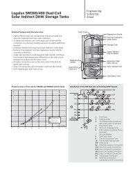
Download - Buderus
Download - Buderus
Download - Buderus
- No tags were found...

Create successful ePaper yourself
Turn your PDF publications into a flip-book with our unique Google optimized e-Paper software.
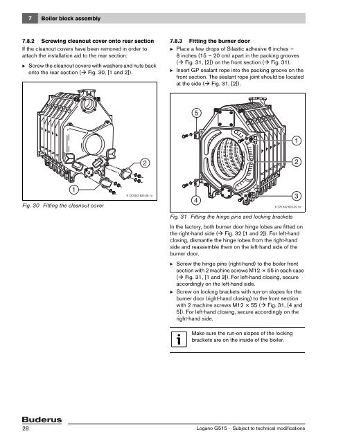
7 Boiler block assembly7.8.2 Screwing cleanout cover onto rear sectionIf the cleanout covers have been removed in order toattach the installation aid to the rear section:B Screw the cleanout covers with washers and nuts backonto the rear section ( Fig. 30, [1 and 2]).7.8.3 Fitting the burner doorB Place a few drops of Silastic adhesive 6 inches –8 inches (15 – 20 cm) apart in the packing grooves( Fig. 31, [2]) on the front section ( Fig. 31).B Insert GP sealant rope into the packing groove on thefront section. The sealant rope joint should be locatedat the side ( Fig. 31, [2]).51221Fig. 30 Fitting the cleanout cover6 720 642 623-28.1o436 720 642 623-29.1oFig. 31 Fitting the hinge pins and locking bracketsIn the factory, both burner door hinge lobes are fitted onthe right-hand side ( Fig. 32 [1 and 2]). For left-handclosing, dismantle the hinge lobes from the right-handside and reassemble them on the left-hand side of theburner door.B Screw the hinge pins (right-hand) to the boiler frontsection with 2 machine screws M12 × 55 in each case( Fig. 31, [1 and 3]). For left-hand closing, secureaccordingly on the left-hand side.B Screw on locking brackets with run-on slopes for theburner door (right-hand closing) to the front sectionwith 2 machine screws M12 × 55 ( Fig. 31, [4 and5]). For left-hand closing, secure accordingly on theright-hand side.Make sure the run-on slopes of the lockingbrackets are on the inside of the boiler.28Logano G515 - Subject to technical modifications