2D BEAMS
2D BEAMS
2D BEAMS

Create successful ePaper yourself
Turn your PDF publications into a flip-book with our unique Google optimized e-Paper software.
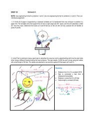
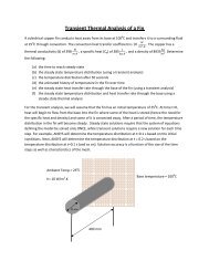
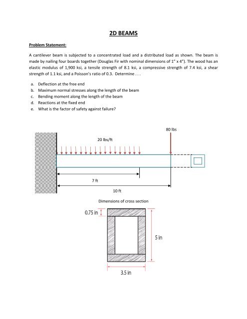
<strong>2D</strong> <strong>BEAMS</strong>Problem Statement:A cantilever beam is subjected to a concentrated load and a distributed load as shown. The beam ismade by nailing four boards together (Douglas Fir with nominal dimensions of 1” x 4”). The wood has anelastic modulus of 1,900 ksi, a tensile strength of 8.1 ksi, a compressive strength of 7.4 ksi, a shearstrength of 1.1 ksi, and a Poisson’s ratio of 0.3. Determine . . .a. Deflection at the free endb. Maximum normal stresses along the length of the beamc. Bending moment along the length of the beamd. Reactions at the fixed ende. What is the factor of safety against failure?20 lbs/ft80 lbs7 ft10 ftDimensions of cross section
ANSYS procedure:1. Preprocessor > Element type > Add/Edit / Delete > Add > <strong>2D</strong> elastic 32. Preprocessor > Real constants > Add/Edit/Delete > Add > OK(Area =10.5, Izz = 29.313, Height =5, (Don’t worry about the other parameters now))3. Preprocessor > Material properties > Material models > Structural > Linear > Elastic > IsotropicEnter EX = 1.9 10 and PRXY = 0.34. Preprocessor > Create > Keypoints > In active CSKey points X Y Z1 0 0 02 84 0 03 120 0 05. Preprocessor > Create > Lines > Straight lines(Click on the key points 1 and 2 to make line 1 and on 2 and 3 to make line 2)6. Preprocessor > Meshing > Sizectrls > Manual size > Lines > Alllines > Element edge length = 47. Preprocessor > Meshing > Mesh > Lines > Pick all8. Utility Menu : Plot ctrls > Numbering (Turn element numbering on)9. Utility Menu : Plot > Multiplots10. Utility Menu : List elements > Nodes and attributes11. Utility Menu : List > Nodes
Applying loads:12. Solution > Define loads > Apply > Structural > Displacement > On keypoints >(Pick first keypoint and fix all DOF)13. Solution > Define loads > Apply > Structural > Force /Moment > On keypoints(Pick keypoint at the end of the beam and apply Fy = ‐80)14. Solution > Define loads > Apply > Structural > Pressure > On beams(Select the “box” radio button and select the desired elements)(apply a pressure of VALI = 1.67, where 20 lbs/ft = 1.67 lbs/in; note that a unit thickness of loadapplication is assumed; if you don’t enter a VALJ value, then ANSYS assumes a uniform load)15. Solution > Solve > Current LSPost processing:16. General Postproc > Plot results > Deformed shape > Def + undef edge17. General Postproc > Element table > Define table > AddName =SMAXI, by sequence number > NMISC= 118. General Postproc > Element table > Define table > AddName =SMAXJ, by sequence number > NMISC= 3
19. General Postproc > Plotresults > Contour Plot >Line element resultsChoose SMAXI for thefirst blank and SMAXJfor the second blank >OKThis shows thevariation in themaximum normalstress along the beam.20. General Postproc > Element Table > Define table > AddName = MOMENTI, by sequence number > SMISC = 621. General Postproc > Element Table > Define table > AddName = MOMENTJ, by sequence number > SMISC = 1222. General Postproc > Plotresults > Contour plot >Line element resultsChoose MOMENTI forthe first blank andMOMENTJ for thesecond blank
Summary of results:1. Deflection at the free end of the beam is 1.121 in2. Stresses and moments along the length of the beam:ElementStress at node I Stress at node J Moment at node I Moment at node J(psi)(psi)(lb‐in)(lb‐in)1 1321.2 1247.2 ‐15492. ‐14624.2 1247.2 1175.5 ‐14624. ‐13783.3 1175.5 1106.0 ‐13783. ‐12969.4 1106.0 1038.9 ‐12969. ‐12181.5 1038.9 973.98 ‐12181. ‐11420.6 973.98 911.37 ‐11420. ‐10686.7 911.37 851.04 ‐10686. ‐9978.68 851.04 792.98 ‐9978.6 ‐9297.89 792.98 737.20 ‐9297.8 ‐8643.810 737.20 683.70 ‐8643.8 ‐8016.611 683.70 632.48 ‐8016.6 ‐7416.012 632.48 583.54 ‐7416.0 ‐6842.213 583.54 536.88 ‐6842.2 ‐6295.014 536.88 492.50 ‐6295.0 ‐5774.615 492.50 450.39 ‐5774.6 ‐5281.016 450.39 410.57 ‐5281.0 ‐4814.017 410.57 373.02 ‐4814.0 ‐4373.818 373.02 337.75 ‐4373.8 ‐3960.219 337.75 304.77 ‐3960.2 ‐3573.420 304.77 274.06 ‐3573.4 ‐3213.421 274.06 245.62 ‐3213.4 ‐2880.022 245.62 218.33 ‐2880.0 ‐2560.023 218.33 191.04 ‐2560.0 ‐2240.024 191.04 163.75 ‐2240.0 ‐1920.025 163.75 136.46 ‐1920.0 ‐1600.026 136.46 109.17 ‐1600.0 ‐1280.027 109.17 81.875 ‐1280.0 ‐960.0028 81.875 54.583 ‐960.00 ‐640.0029 54.583 27.292 ‐640.00 ‐320.0030 27.292 0.39715E‐10 ‐320.00 0.46566E‐093. Reaction at the fixed end:NODE Fx(lb) Fy(lb) Moment (lb-in)1 0.0000 220.28 15492
4. The peak tensile and compressive stresses have identical values since the cross section ofthe beam is symmetric. Since the compressive strength is lower than the tensile strength,the beam is expected to fail in compression. The factor of safety is 1321.2 =, Solving for the factor of safety yields 5.6.The BEAM3 element only works for symmetric cross sections and does not compute shearstresses in the beam. This is because the element as applied here relies only on the grosssection properties (area, moment of inertia, and height) and does not perform anycalculations based on the shape of the cross section. Since the shear stress in the beamdepends on the thickness of the beam at the neutral axis ( ), the BEAM3 element cannot determine the shearing stress. So, shearing failure, which could occur at the neutral axisof this beam, can not be evaluated numerically using this element.This tutorial was developed by David Hall and Sai Ravi Kanth Tummala © 2008