Mode Lighting Evolution-eDIN DriverWorks Getting Started
Mode Lighting Evolution-eDIN DriverWorks Getting Started
Mode Lighting Evolution-eDIN DriverWorks Getting Started
You also want an ePaper? Increase the reach of your titles
YUMPU automatically turns print PDFs into web optimized ePapers that Google loves.
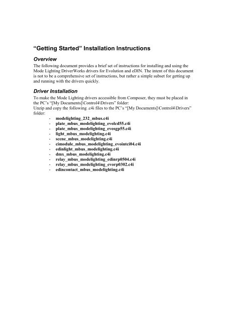
“<strong>Getting</strong> <strong>Started</strong>” Installation InstructionsOverviewThe following document provides a brief set of instructions for installing and using the<strong>Mode</strong> <strong>Lighting</strong> <strong>DriverWorks</strong> drivers for <strong>Evolution</strong> and <strong>eDIN</strong>. The intent of this documentis not to be a comprehensive set of instructions, but rather a simple subset for getting upand running with the drivers quickly.Driver InstallationTo make the <strong>Mode</strong> <strong>Lighting</strong> drivers accessible from Composer, they must be placed inthe PC’s “[My Documents]\Control4\Drivers” folder:Unzip and copy the following .c4i files to the PC’s “[My Documents]\Control4\Drivers”folder:- modelighting_232_mbus.c4i- plate_mbus_modelighting_evolcd55.c4i- plate_mbus_modelighting_evosgp55.c4i- light_mbus_modelighting.c4i- scene_mbus_modelighting.c4i- cimodule_mbus_modelighting_evointci04.c4i- edinlight_mbus_modelighting.c4i- dmx_mbus_modelighting.c4i- relay_mbus_modelighting_edinrp0504.c4i- relay_mbus_modelighting_evorp0302.c4i- edincontact_mbus_modelighting.c4i
Adding Drivers to a Control4 ProjectThe following steps illustrate adding and configuring the various drivers within aControl4 project:1. Start Composer and connect to a controller with a working project2. Add the ‘<strong>Mode</strong> <strong>Lighting</strong> MBus Interface” driver to theprojectIn Composer’s ‘System Design’ view, find the “<strong>Mode</strong><strong>Lighting</strong> MBus Interface” entry under the “Search” tabunder the “—others—“ Device Type and Double-clickthis entry to add it to the project.IMPORTANT NOTE: The <strong>Mode</strong> <strong>Lighting</strong> MBusInterface driver should always be added FIRST to aproject BEFORE adding any other <strong>Mode</strong> <strong>Lighting</strong>drivers. This is because the other ‘client’ drivers aredesigned to ‘Auto-Bind’ to the MBus driver when theyare added. If the MBus driver is not present whenother drivers are added, they cannot auto-bind, andtherefore they would need to EACH be manuallybound at a later time!3. Add “<strong>Mode</strong> <strong>Lighting</strong> LCD Plate” and “<strong>Mode</strong> <strong>Lighting</strong> SGP Plate” drivers to theproject as needed to represent each plate in the physical system4. Add “<strong>Mode</strong> <strong>Lighting</strong> Contact Input Module” drivers to the project as needed torepresent each contact input module in the system.5. Add “<strong>Mode</strong> <strong>Lighting</strong> Universal Pack Channel”,“<strong>Mode</strong> <strong>Lighting</strong> Universal <strong>eDIN</strong> Channel” or “<strong>Mode</strong><strong>Lighting</strong> Universal Scene” drivers to the project asneeded to represent each load (generally a load notpart of a scene) or scene in the physical system. Thesedrivers can be found under the “Search” tab under the“<strong>Lighting</strong>” Device Type:
Make Driver ConnectionsThe only critical connection which must be made to begin operation at this point is theSerial Port connection:1. In the Composer ‘Connections’ view select the “<strong>Mode</strong> <strong>Lighting</strong> MBus Interface”entry.2. Under ‘Control Inputs’ in the top right pane, drag the ‘Serial 232’ connectiondown to the bottom-right pane and onto the appropriate physical serial portbinding.IMPORTANT NOTE: When using an HC300, serial port #1 should be avoided dueto its lack of hardware flow control signals (see known limitations section)
Driver ConfigurationThe following section briefly details configuration of the various driver entries foroperation.1. In the Composer ‘System Design’ view select the “<strong>Mode</strong> <strong>Lighting</strong> MBusInterface” entry.2. Under the “Properties” tab, verify that communications to the EVO-INT-232 areestablished:3. If using <strong>eDIN</strong> modules only, make sure to set the MBus Master property to Yes inthe EVO-INT-232 properties.4. Select the “<strong>Mode</strong> <strong>Lighting</strong> LCD Plate” entry.5. Configure the ‘Plate Address’ to match the physical address of the appropriateplate in the system:6. Click the ‘Set’ button. The appropriate plate in the system should now beinitialized/refreshed.7. Select the “<strong>Mode</strong> <strong>Lighting</strong> SG Plate entry.8. Configure the ‘Plate Address’ to match the physical address of the appropriateplate in the system. Click the ‘Set’ button.9. Select the “<strong>Mode</strong> <strong>Lighting</strong> Contact Input Module” entry.10. Configure the ‘Module Address’ to match the physical address of the appropriatemodule in the system. Click the ‘Set’ button.11. Select the ‘Light’ entry (which corresponds to the ‘<strong>Mode</strong> <strong>Lighting</strong> Universal PackChannel’ or ‘<strong>Mode</strong> <strong>Lighting</strong> Universal <strong>eDIN</strong> Channel’ instance added to theproject)
12. Configure the ‘Channel Number’, ‘Channel Type’, and ‘Pack/Module Address’ tomatch the physical properties of the light channel in the system:13. Click the ‘Set’ button for each entry.14. Select the ‘Light’ entry (which corresponds to the ‘<strong>Mode</strong> <strong>Lighting</strong> UniversalScene’ instance added to the project)15. Configure the ‘Scene Number’ to match the scene to control within the system.Click the ‘Set’ button.Known Limitations1. Deleting a driver element from a Control4 project may cause Director to crash.2. The EVO-INT-232 interface will not work on Serial Port #1 of an HC300controller.- The EVO-INT-232 interface expects to see hardware flow line CTS drivenfrom the host it is connected to. Serial Port #1 on an HC300 does not drivethis line. Therefore, the EVO-INT-232 must be used on Serial Port #2 instead.3. Button Color messages are not properly sent from the Light or Scene drivers to alinked keypad.Control4 Keypads (or <strong>Mode</strong> Plates) which have been bound to the LINKCONTROL bindings of the <strong>Mode</strong> <strong>Lighting</strong> Light or Scene drivers will not receivecolor messages to match the LED colors programmed in the properties page ofthe Light or Scene drivers. Consequently, the colors displayed on the linkedkeypad will be incorrect.


